


Leaderboard
-
conedodger
Free Member13Points12,649Posts -

Zed Head
Free Member11Points19,329Posts -
zKars
 Subscriber
 10Points3,781Posts
 -
Patcon
Subscriber6Points11,185Posts


Popular Content
Showing content with the highest reputation since 12/12/2025 in all areas
-
6 pointsHere are the thread rules. Again. For any hardware you are likely to encounter. 4 x 0.7 5 x 0.8 6 x 1.0 8 x 1.25 10 x 1.5 - bolts that thread into the engine block. Trans, head, brackets, 10 x 1.25 - All other M10 bolts, ie suspension and body are 1.25 12 x 1.25 - wheel studs, front spindle to steering arm, trans mount (later), TC rod ends, Flywheel , spindle pins 14 x 1.5 - diff strap bolts, front control arm pins 16 x 1.5 - Crank bolt 20 x 1.5 - Rear Stub Axles Threaded pipe fittings are all BSPT, A/C and EGR excluded. There is a 1/4x28 SAE thread somewhere for you to find as a test. There are 7/16-20 SAE too. Another test. And what the heck is up with those short fat rear control arm bushing bolts? And why do I have 2 or 3 dozen of them? The first 7 on the list are the ones you should have taps and dies for on hand at all times. Better yet the thread restoring kind, not the thread making kind. Print this out and post it on the shop wall.6 points
-
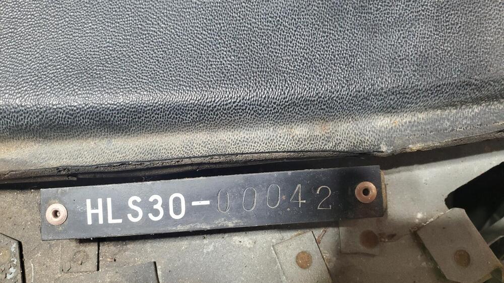
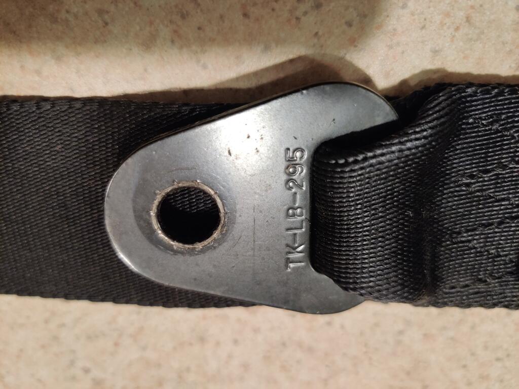
3 pointsYup, 7/16-20 for the seat belts. M12 is a valid spec as well from some DOT document I found 15 years ago when I was researching aftermarket replacement belts. No idea what manufacturers adopted world wide. Also curious what seat belt threads were used on the various early 60’s datsuns (411, roadsters etc). The 1/4-28 are on the two Z hood bumper . Craziest thing I’ve ever seen. Must have been supplier determined at the time.3 points
-
3 pointsI posted a recent issue with my Mallory ignition. The Uni-lite ignition module would test bad when the car would stop working but after it sat for awhile it would test fine and the car would run again. After changing the ignition module a couple of times, and with some input from this forum, it turns out that a PO installed a second shunt resistor in series with the first one. I removed the second resistor and so far the car has been working. I think the issue with the shunt was that on removing it, I observed the exposed coil of wire in the shunt was damaged and likely was not giving a constant resistance, possibly no continuity at times. Even if you have just the single shunt resistor, if it fails like this one did, it might cause the same issue.3 points
-
Yesterday, the postman delivered a big package from Japan again. This time with a load of cool documents. The first one (Bottom right) is the Race and Rally preparation manual. I bought this one for a friend, since I already own one. But it's always cool to see those. The second one is a combined S30S(A) / GS30S(A) brochure for the standard Fairlady Z / Z-L and the 2by2 versions. See also Color samples at the bottom right: For whatever reason, one of the Japanese lots included a US-Market 240Z Brochure. Not something I would usually buy, but since I didn't have it in printed form yet it's cool to have it anyway. From the Japanese market again, I got this Fairaldy Z / 240 Operation manual, which also includes the Z432 versions. These are particularly useful to find some details of the interior for my knowledge posts. This is the later version that also covers the ZG and other HS30 variants (the early versions only covered the Z / Z-L and Z432): Then I got two of the Japanese marked fold-out Fairlady Z sales brochures. It's basically a brochure on one side and a ZG Poster on the other side. I was buying one, when a second one was included in a Lot of documents. Once I got them, i realized that i already had one, So now i end up with three. But, I intend to frame one as a Poster and I realized that there are different versions. Both the Material (paper-weight) and print is different: For me no doubt the coolest item is this Nissan Racing school brochure: With the Checkman Sponsored GTS-II Works car on the back. Especially this version of the car with the "Batmobile" rear aero. I just love everything about it. The sponsoring, the aero, the livery. Another Magazine was the "Nissan Graph" Customer magazine from April 1985. Which also included some racing school details. I'm working on a knowledge post about this, that's why I started to collect some information about it. One general 1971 Japanese Nissan brochures also included the ZG: And the general lineup on the inside. I guess this magazine was issued at a Car show in 1971 or at the dealerships? It also included some cool drawings of the 216X Concept car: Another similar brochure (without date) from Nissan Tokyo, which again shows the ZG and some other nice cars: On the inside you find the lineup from that time, but with a regular Fairlady Z and Z-L shown. Another cool book is the J's Tipo Fairlady Z Archives (002). J's Tipo is a Japanese car magazine, and this book is basically a collection of all their Fairlady Z related stories from various years, compiled in one book. After I met Morita san, the Author of the Fairlady Z Story and History books, in Japan recently, I had to get "Volume 2" of the book. I've owned Vol 1 for a long time, but never the second one, since it wasn't so relevant for the S30. But now I had to get it :-) Then i also got this Jack and tool stowage reproduction Sticker from Germany. I had this Genuine Datsun Parts sticker for a long while and always wondered how I can present it. When I found this piece of Aluminum sheet, I got the idea to make a sign out of it. So I cut the aluminum. And then put the sticker on it. So I ended up with this cool sign. And found a good little Spot for it: I also found a nice place for the NISMO sign, but it looks a bit small on this big wall, next to the huge Datsun sign. I have some projects planned for the next week and hope I can get back working on the car itself, so stay tuned for some updates, soon.3 points
-
I remember reading an industry website several years ago where the writer predicted that the only distinction between mainstream brands of power tools would be aesthetics (colours, textures, legacy, etc). Looking at what I see in 2025's North American market, I'm inclined to agree. But I think that only applies to ~ revered old-school USA brands like Porter, DeWalt, B&D, etc. For comparison, look at what's happened to old-school non-automotive brands like 'Schwinn', 'Singer', 'Sunbeam', 'GE', 'RCA', etc. Offshore' brands (Bosch and Makita come to mind) might have a little more to offer than just marketing. Unfortunately, there's no universally-accepted evaluation standard. These days, it's just the 'Wild Wild West' of YouTube evaluators Caveat emptor.2 points
-
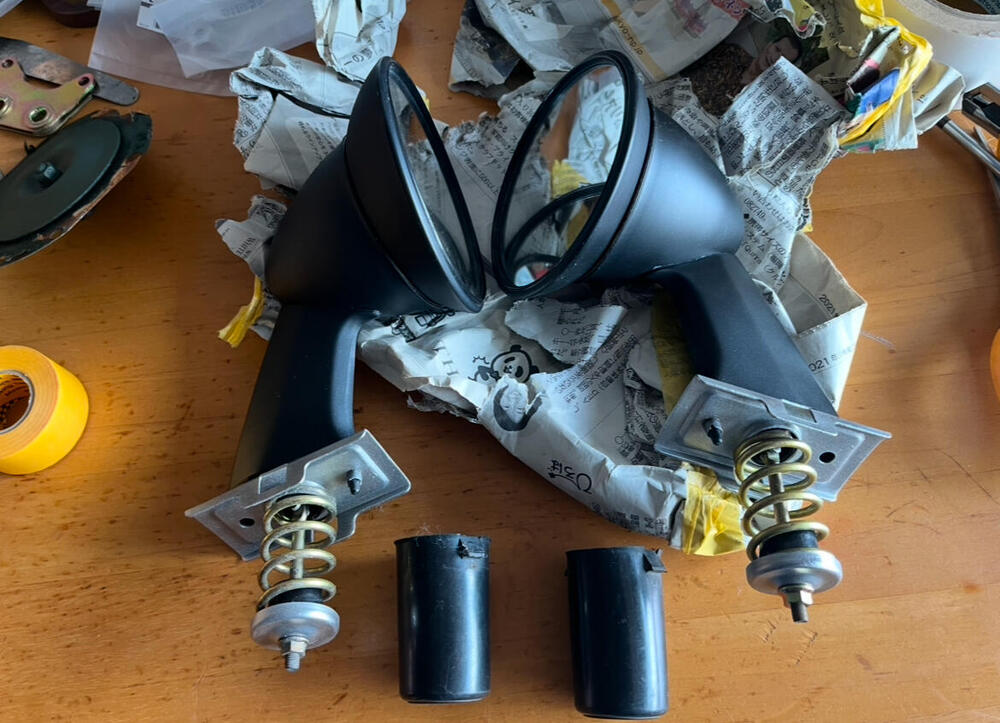
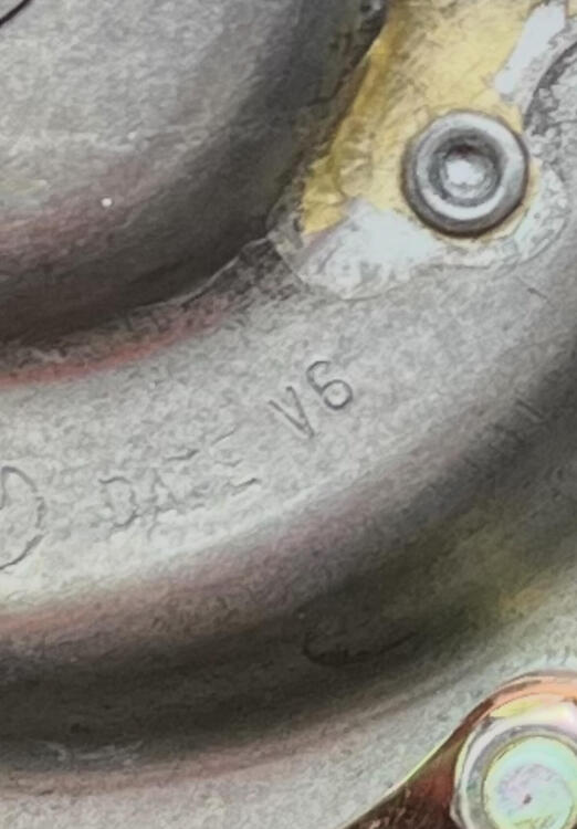
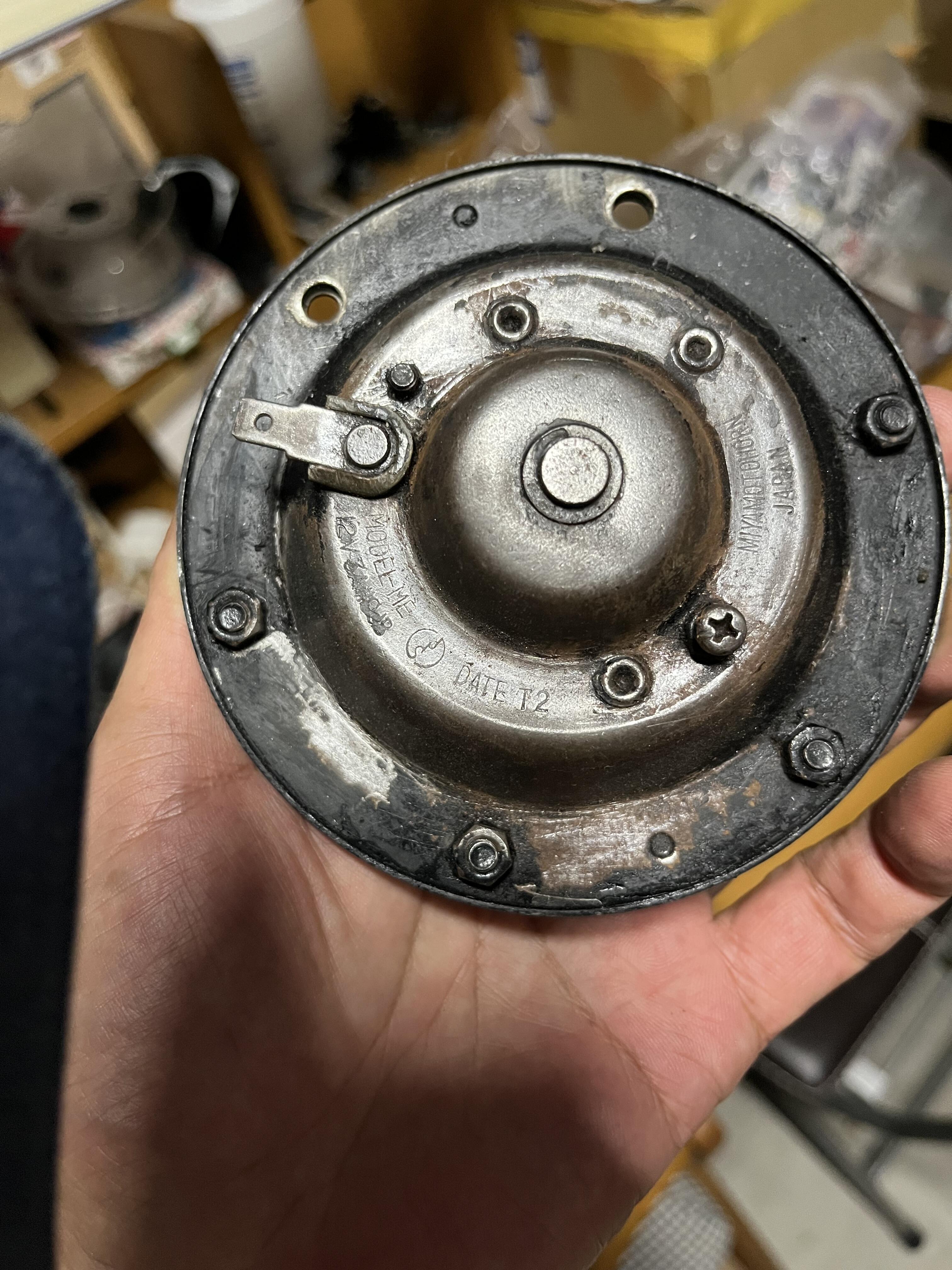
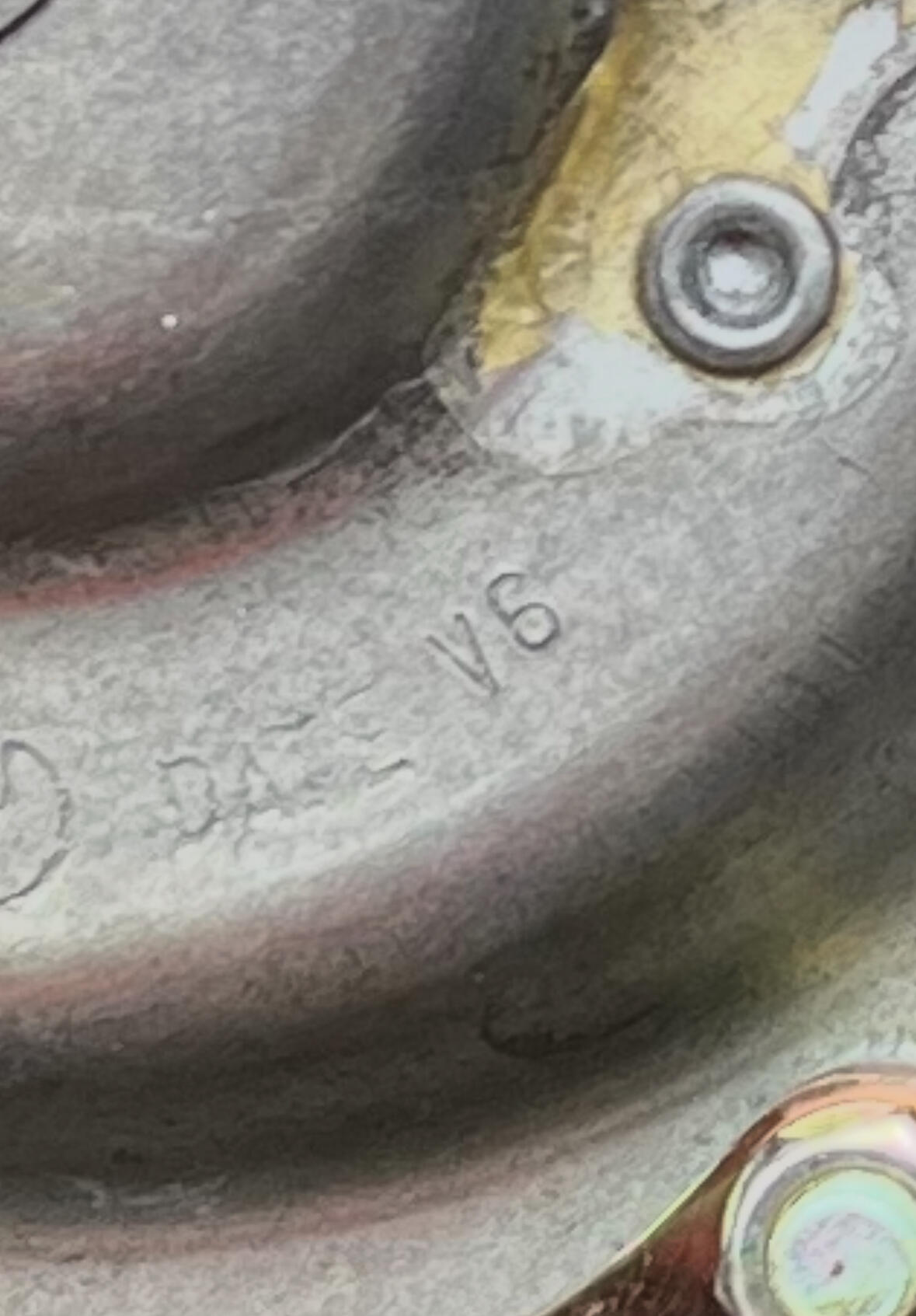
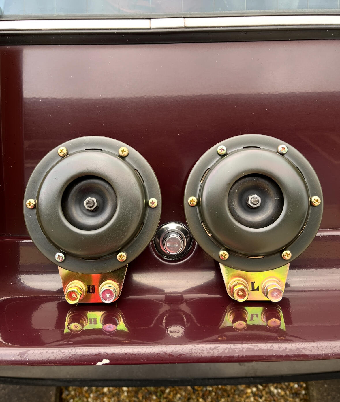
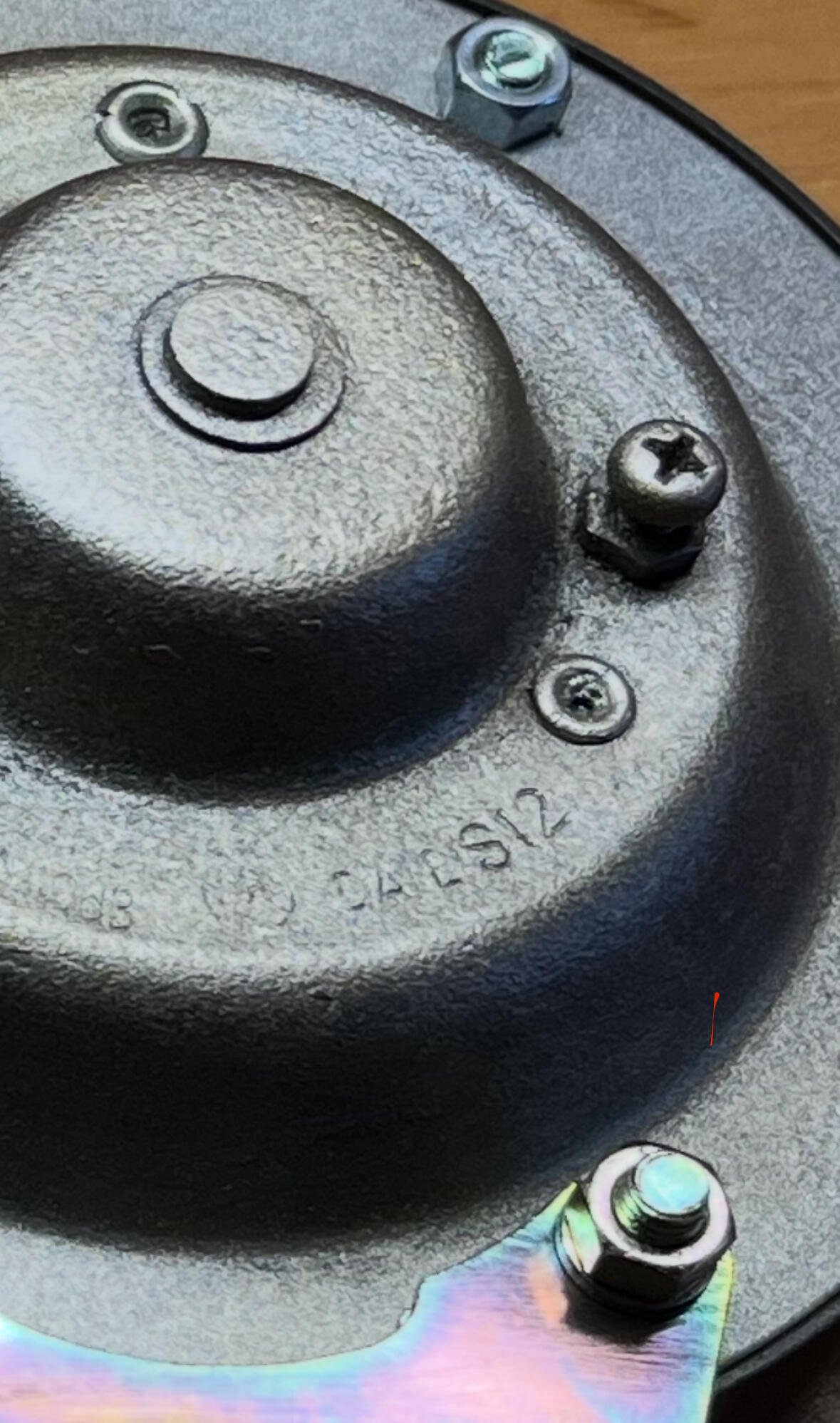
2 pointsHi, I have worked some minor things for mirrors, horns etc. Fairlady Z series has mirrors on the front fenders and the way they mount is completely different from the one for the US. Mirrors have to be flexible when they hit something. The horn, the Higher tone has “H” and te lower tone has “L” shown on the bracket. You see S12, I am sure S means 1969, 12 means December. It makes sense to my 01/1970 Z432. My two 03/1970 cars have T2, indicating 1970 February. Also my 1972 June 240ZG has V6, The rules seemed to apply for all of my cars. Kats


 2 points
 -
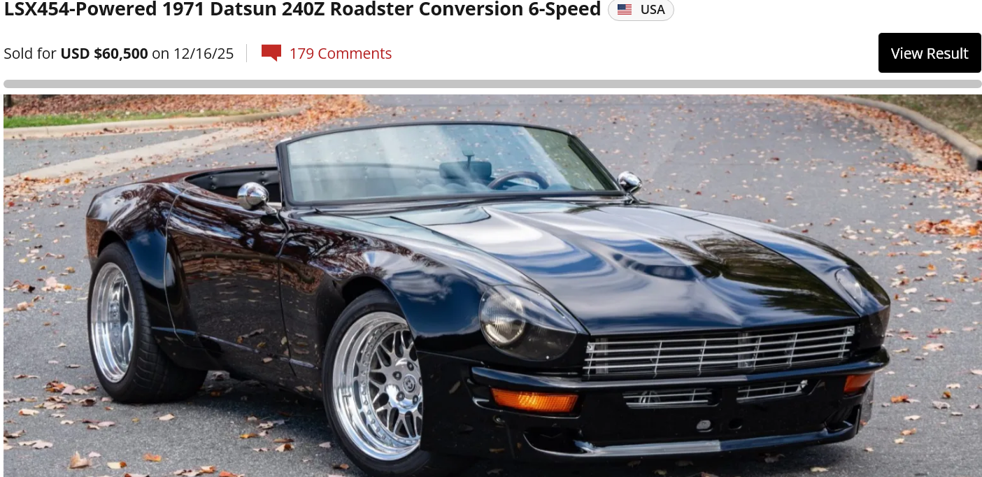
All that hype in the BaT comments and it didn't even get near six-digit territory. For about that same amount of money I'd rather have a C-7 Z06 LZ3 convertible. Similar horsepower and you get a heater, A/C, audio system and a functional convertible top.2 points
-
2 points
-
2 points
-
@EuroDat is the guy I'm pretty sure you're thinking of. He does some amazing things and always has great pictures to share his work.2 points
-
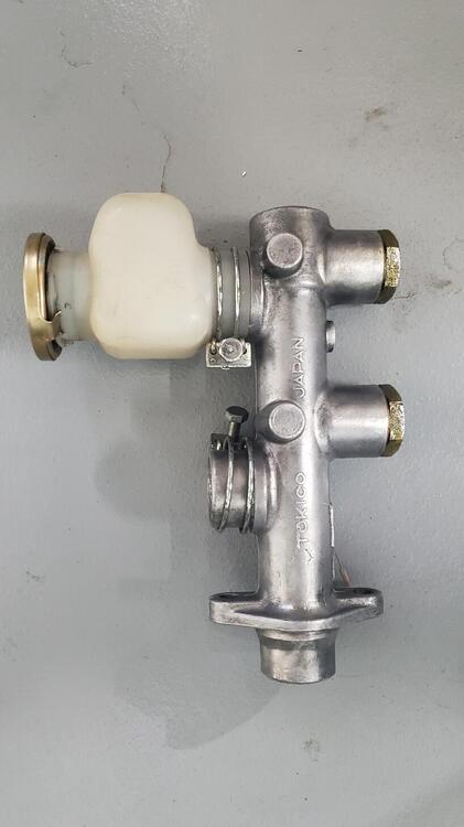
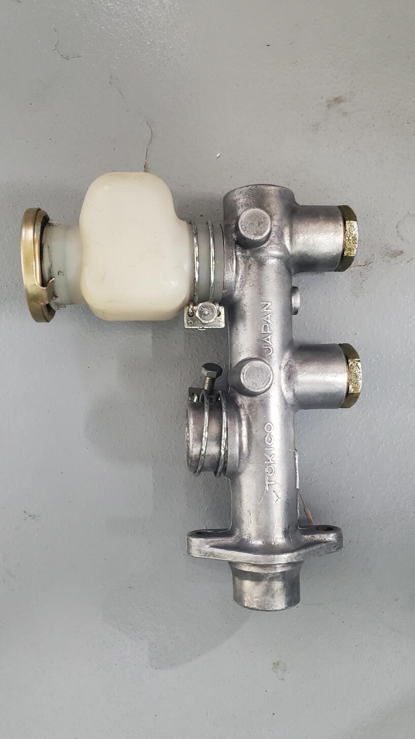
2 pointsI believe the OE spec tor the oil drain plug is 3/8 BSPP. The threads on mine measure 16.43mm major diameter, which is at the low end of the BSPP parallel spec, 16.662mm +0/-0.25mm. I don't have a metric 55 degree thread gauge but my 1.3mm 60 deg. thread gauge is very close to the spec pitch of 1.337mm. https://amesweb.info/screws/bspp-thread-chart-calculator.aspx2 points
-
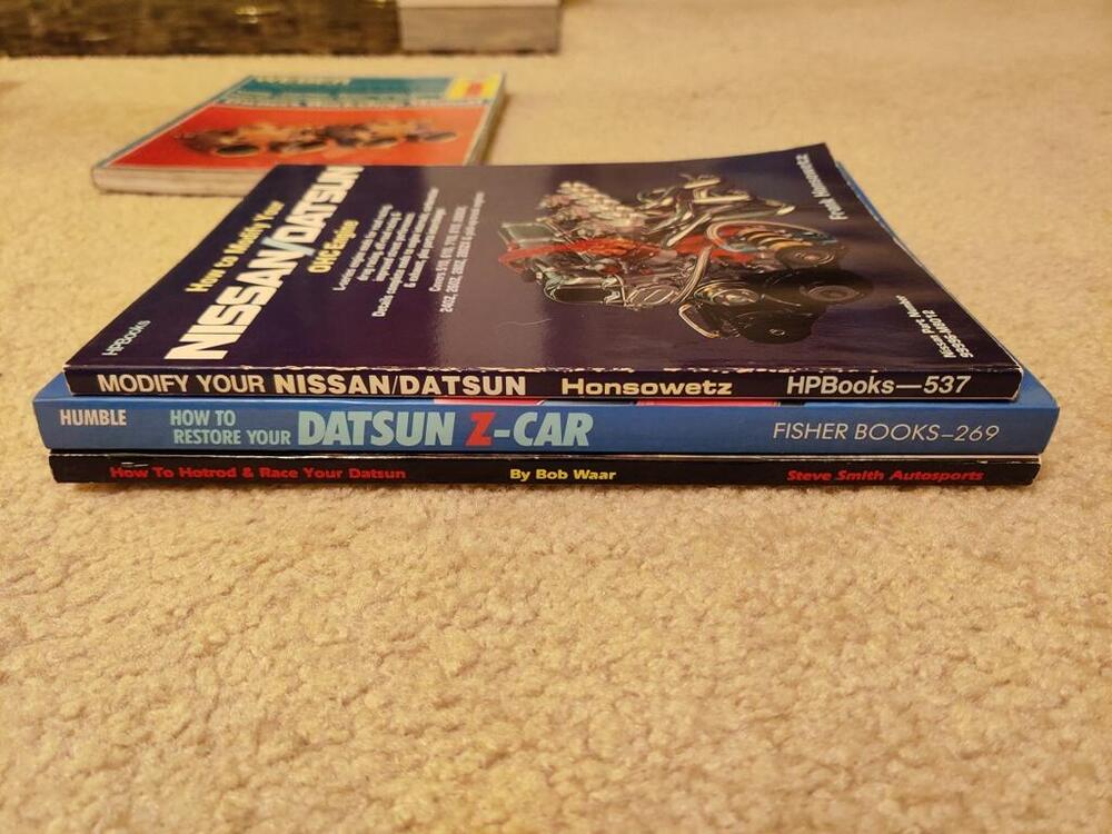
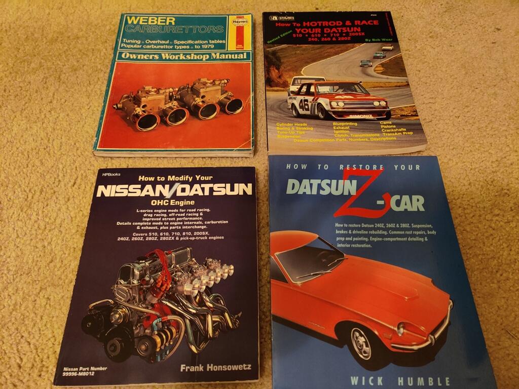
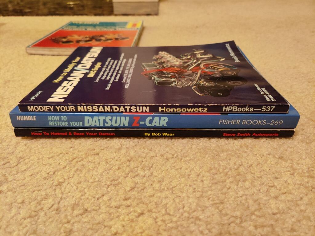
For Sale (Lightly Used) - Datsun Books: How to Hotrod and Race... How to Modify... How to Restore...
2 pointsHow to Modify Your Nissan/Datsun OHC Engine, original edition: has a blemish on the back cover, excellent otherwise: Price is $20 plus shipping How to Hotrod and Race Your Datsun, original edition: In nearly excellent condition: Price is $100 plus shipping How to Restore Datsun Z-Car, original edition I believe (copyright is 1990) - binding shows some light detachment - all info on pages is intact. Overall condition is good Price is $10 plus shipping PM me with questions. ---Garrett
 2 points
 -
2 pointsGreat post. This info really needs to be added to 'Knowledge Base'.2 points
-
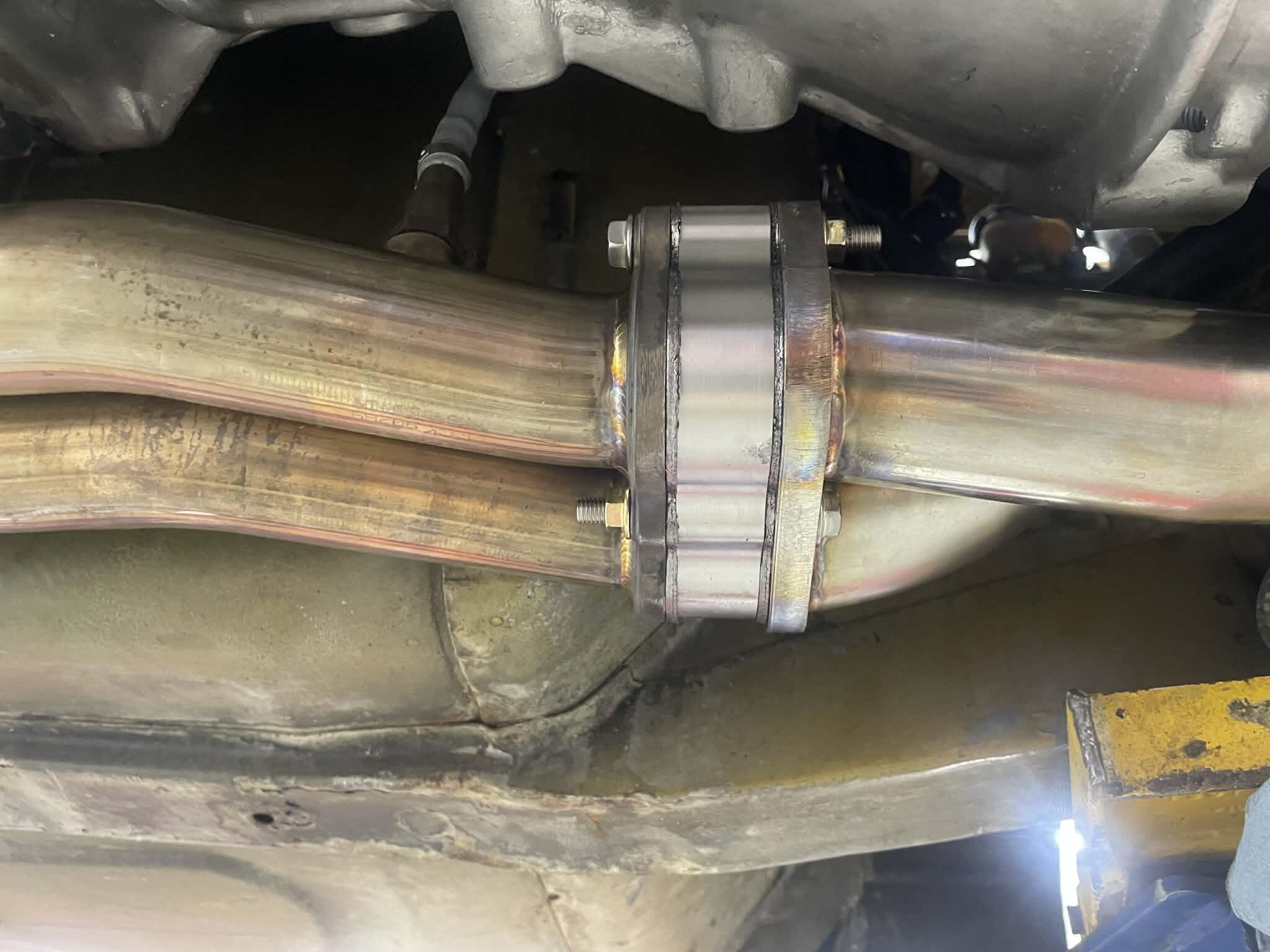
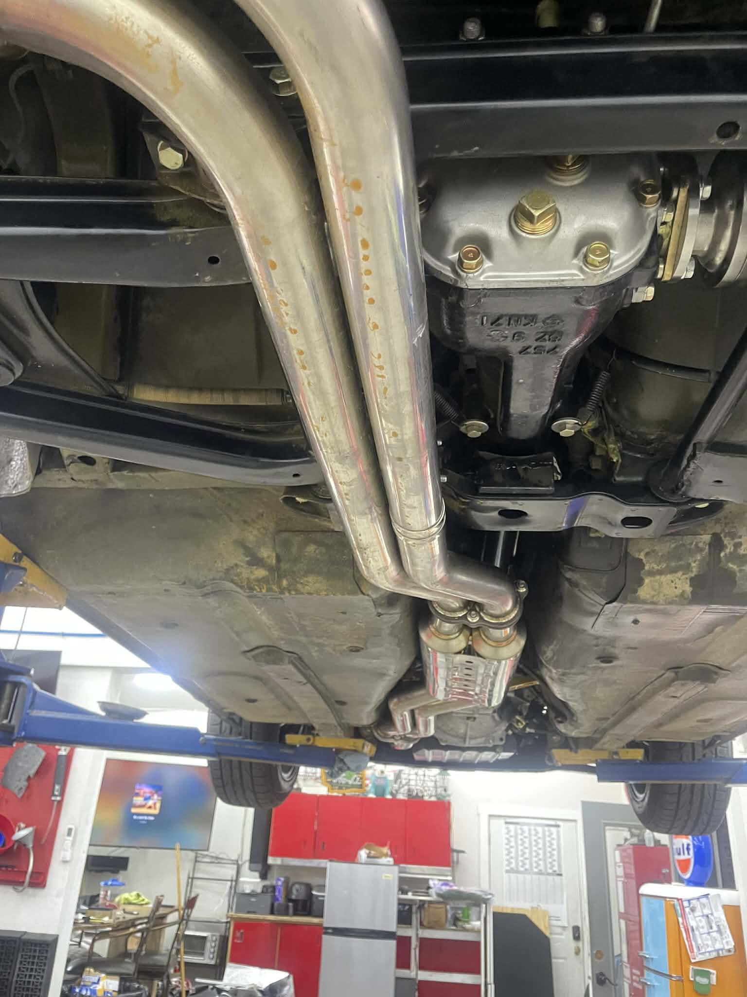
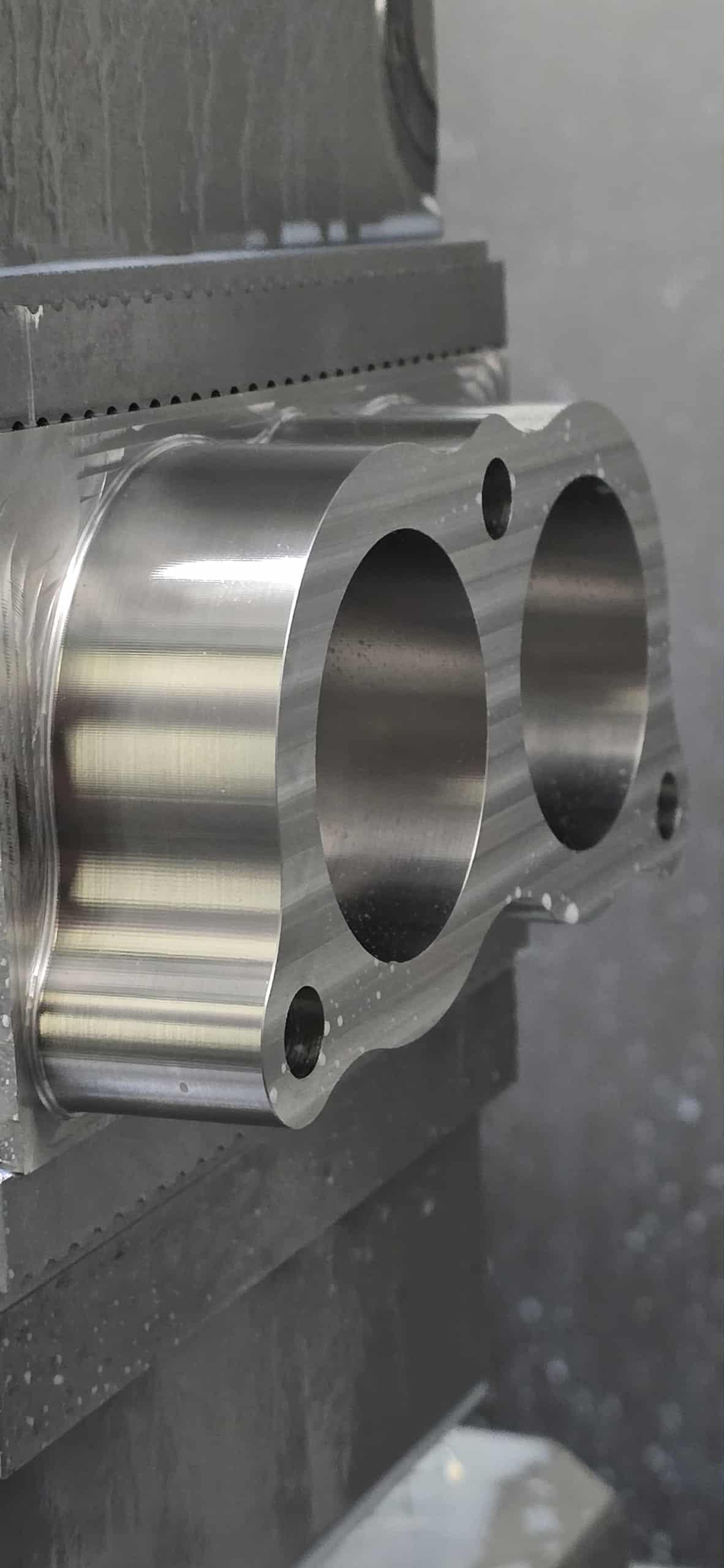
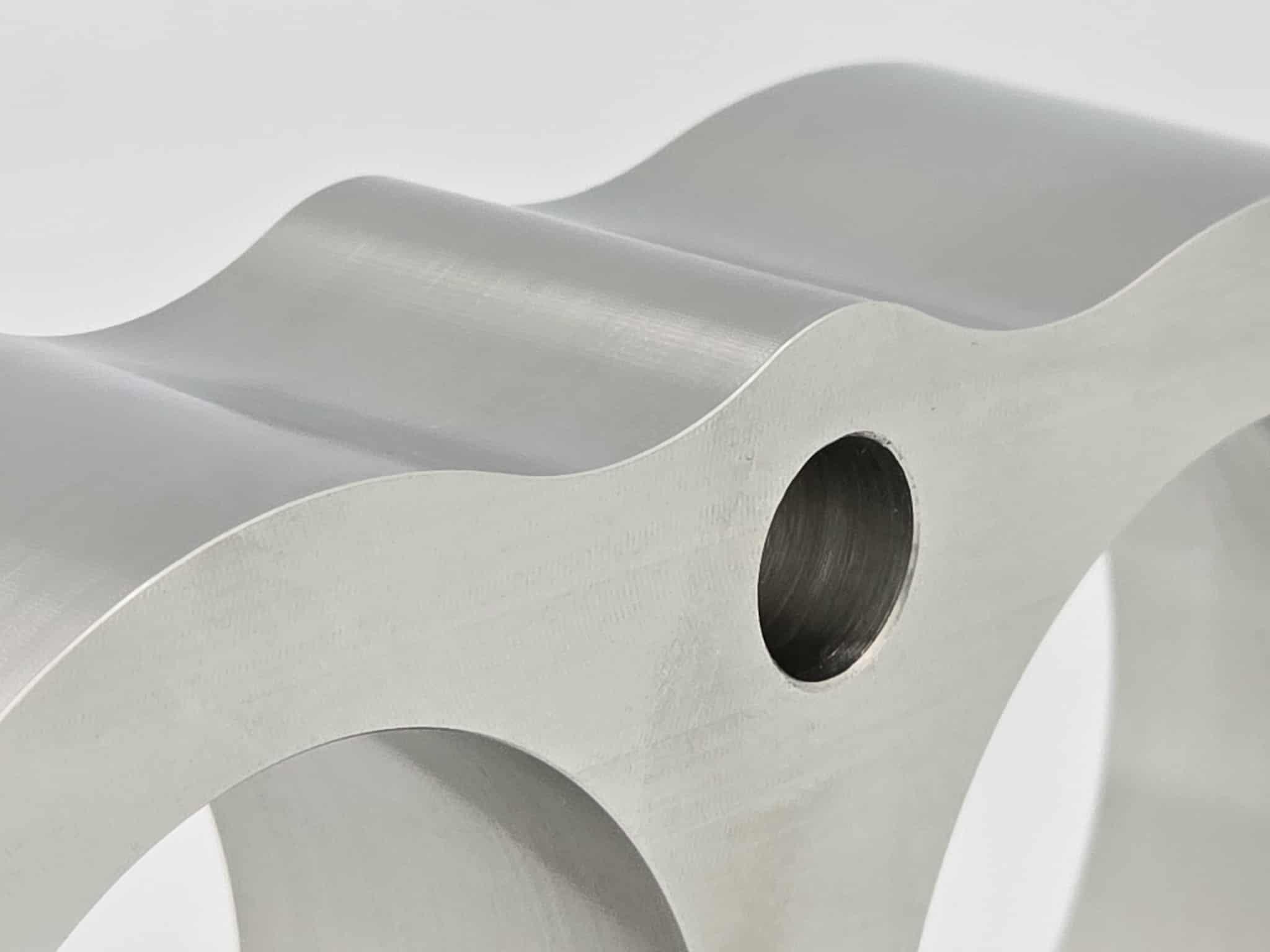
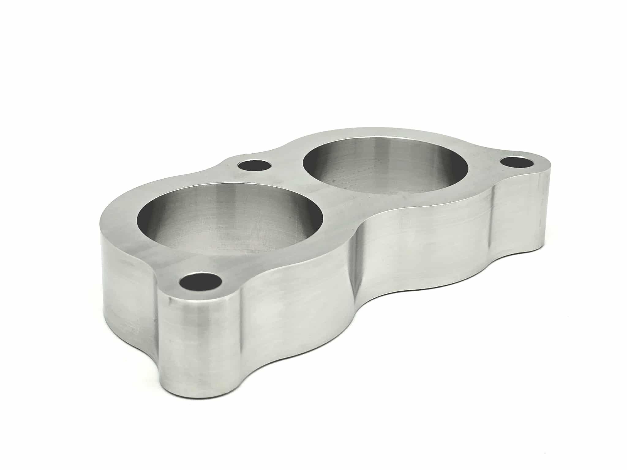
2 pointsFinally got my exhaust finished. With the kenmeri header mated to my Fujitsubo exhaust. There was a small gap between the flanges. Designed up a small spacer. This is 316 stainless.


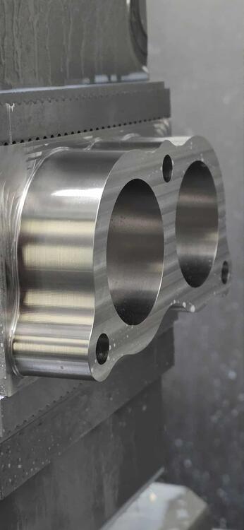

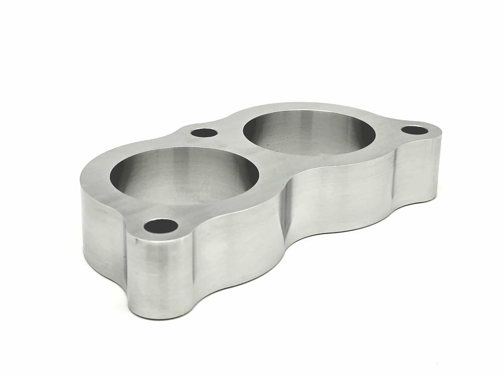 2 points
 -
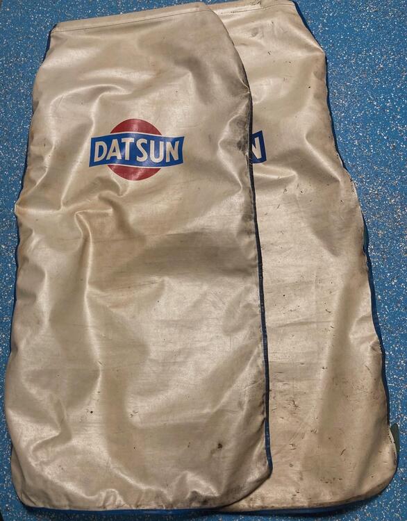
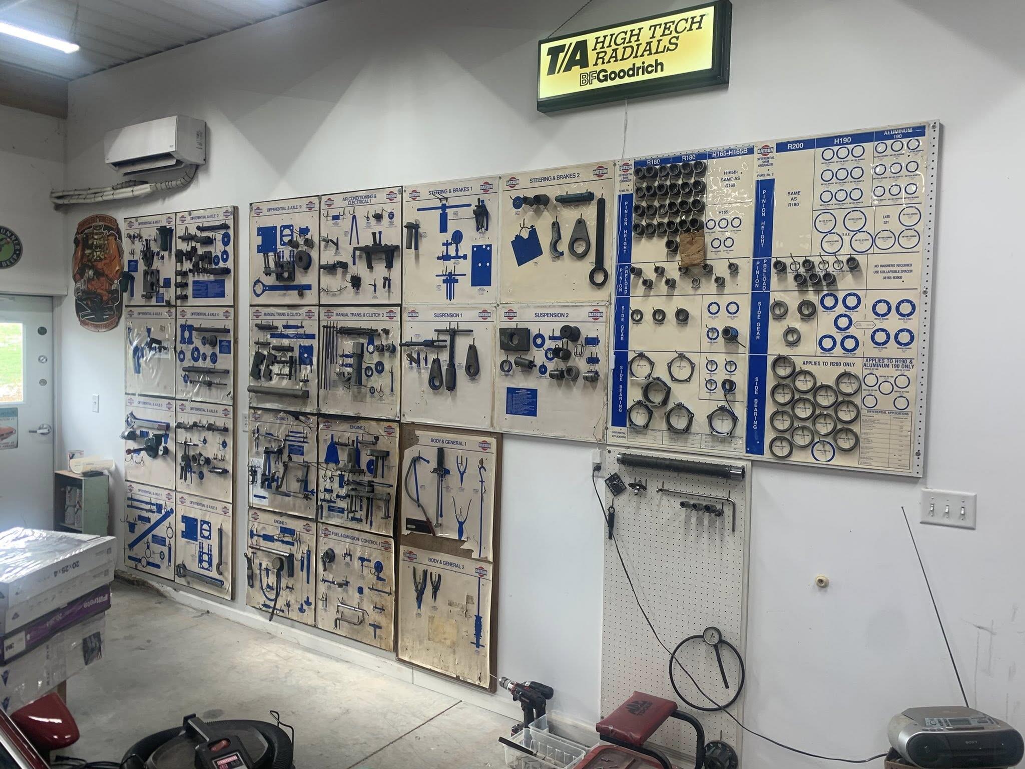
2 pointsRecently a guy on FB posted he had bought a bunch of Datsun tools and tool boards. He has them all cleaned up and mounted on the garage wall. Makes a nice display. I have the Special tools manual from 9/69 and a couple of mechanic seat covers that I really have never seen before. Do any of you have any info on the seat covers?
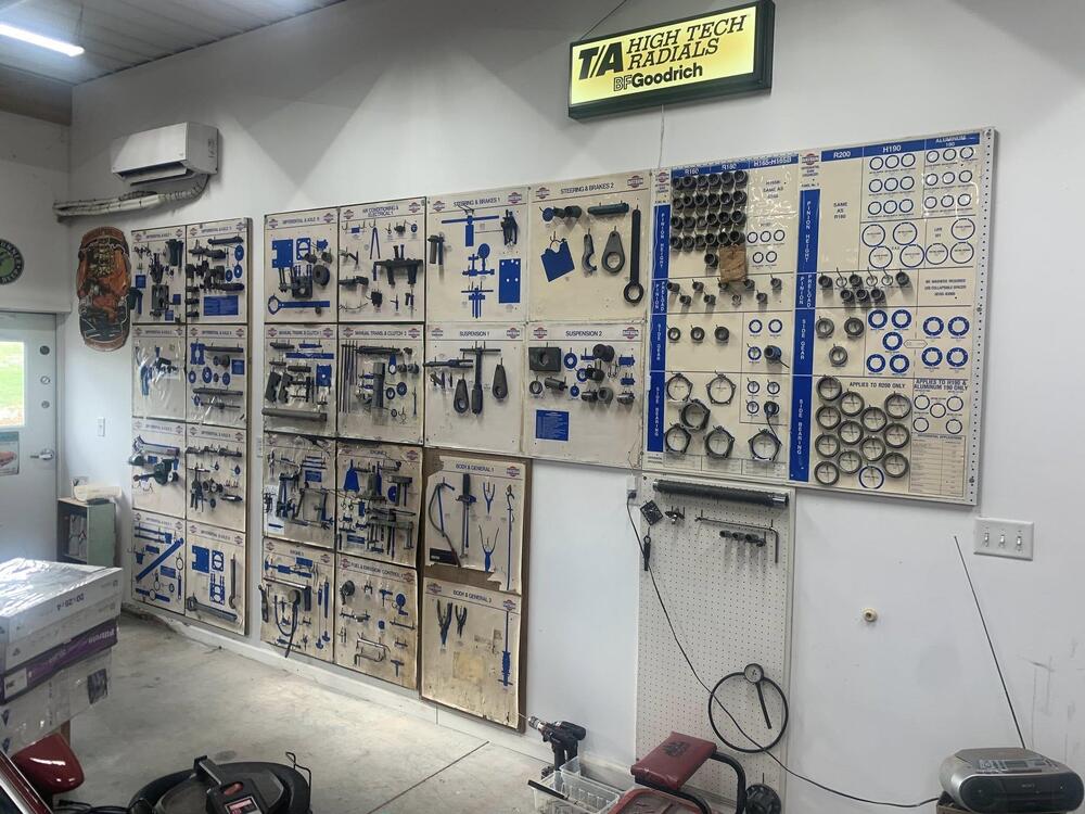
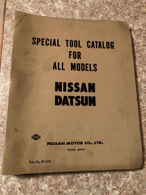
 2 points
 -
It's unfortunate so many cool looking concept cars don't get built or the coolness gets lost in the transition to production line2 points
-
That's what we did with boats, river racing. Put spray paint marks on the inside of the highway guardrails along the river. 13 hundred and 20 feet, run what you brung was like a Bible verse I'll never forget.2 points
-
Missing dovetail on the passenger door, photo 150. Also the rubber weather strip under the door. They weren’t there in 2019 when it was last on BAT. I just remanufactured the early pre 1973 dovetails for my 1970/71 240Z as they were no longer available. Also did the plastic grease reservoir for the steering rack and the plastic cover for the battery. The Vintage Z cars were restored with parts that were available at the time, 1997/98; not always period correct parts but they did the best they could.2 points
-
The next best thing to a 240-Z. Bring a TrailerBobby Rahal's 1967 Toyota 2000GTBid for the chance to own a Bobby Rahal’s 1967 Toyota 2000GT at auction with Bring a Trailer, the home of the best vintage and classic cars online. Lot #224,826.1 point
-
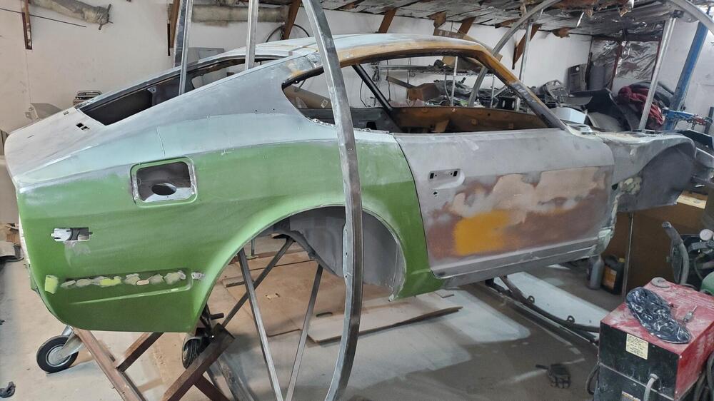
I'm not planning on putting the original distributor points and condenser system back on my 71 240Z. A friend of mine is telling me to use a 123 ignition and an MSD6AL. Good or? Years ago I installed electronic fireball ignition system on an old GMC truck that I still have. I've never once had a problem with that upgrade. I'd like to do the same thing with the Z. Anyone have experience and advice to point me in the right direction. Thanks in advance for the group's help. Restoration update as of 12-16-25.
 1 point
 -
The other thing that often fails on the old distributors is the bearing mechanism under the vacuum advance breaker plate. The bearings and the surface get rusty, the balls stick, and the plastic cage breaks. Most people probably don't notice (I didn't) because it just stops the vacuum advance timing adjustment from working. Here's some instructions showing what's in there. The main difference would be points instead of electronics on top. https://www.atlanticz.ca/zclub/techtips/distributorrebuild/index.html If you have a good functional distributor then a Pertronix unit might be a good choice. If your distributor is gummed up, maybe look around for other options. It's all part of the game.1 point
-
1 pointWell if you think the steering is heavy with the 195 width the 205 should be heavier and the ride will be somewhat rougher. My thinking on tires for these older cars that haven't been modified is mixed. If you want to experience the drivability that Datsun intended you should stick to the original size as closely as possible. That's important to some, not to others. In todays market this really limits the availability of the tires and there in lies another issue. I too have an unmodified Z and just ordered some new wheels and tires for it. Based on tires available I ended up going with a 16" Panasports and 205/55 ultra high performance all-season tires. Nothing crazy but it should tighten up the response some without sacrificing all of the true Z feel. I know this last paragraph doesn't answer your question, just food for thought. Good luck!1 point
-
Hey Cliff put on your Librarian Glasses and solve this one!!1 point
-
Matchboxes appear to be available here https://www.rockauto.com/en/catalog/nissan,1980,280zx,2.8l+l6,1209316,ignition,ignition+control+module+(icm),71721 point
-
1 pointAnd there is that thread on the valve cover breather and trying to find something that will convert it to AN or NPT to run a catch can hose. Seen infinite discussions about it, what folks did to change it, and even some fitting for RB engines someone found that fits, but still waiting to have the actual size stated.1 point
-
The 1979 to 1983 matchbox distributor is a good upgrade.1 point
-
Reading a story about Craftsman tools and found that they were owned by Stanley Black & Decker. Also learned that Stanley and Black & Decker had combined, back in 2010. Very much like Holley. Pretty soon everything everywhere will be made by a single company. https://en.wikipedia.org/wiki/Craftsman_(tools) https://en.wikipedia.org/wiki/Stanley_Black_%26_Decker https://www.holley.com/
 1 point
 -
Wasn't offended. Just surprised that you used a term from the 1980's!1 point
-
I saw your comment @siteunseen Did you break a rule? 🔨1 point
-
1 pointJust for closure I just ordered a set of 16 x 7 Panasport wheels with 0 offset from sportsandclassics.com About the only place I found, will be shipping out today. Super nice folks to deal with. Tad1 point
-
200k seems like a stretch. I like it but it wouldn't be worth the cost of admission to me1 point
-
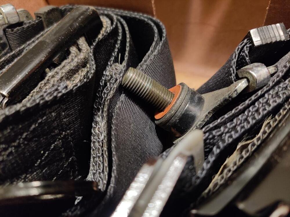
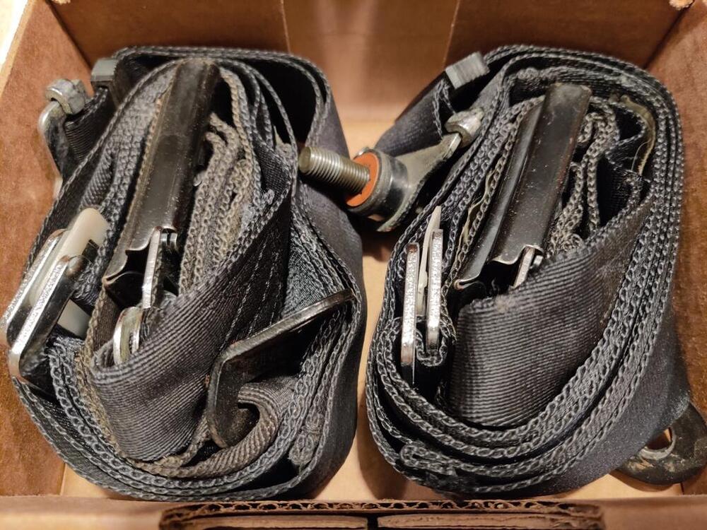
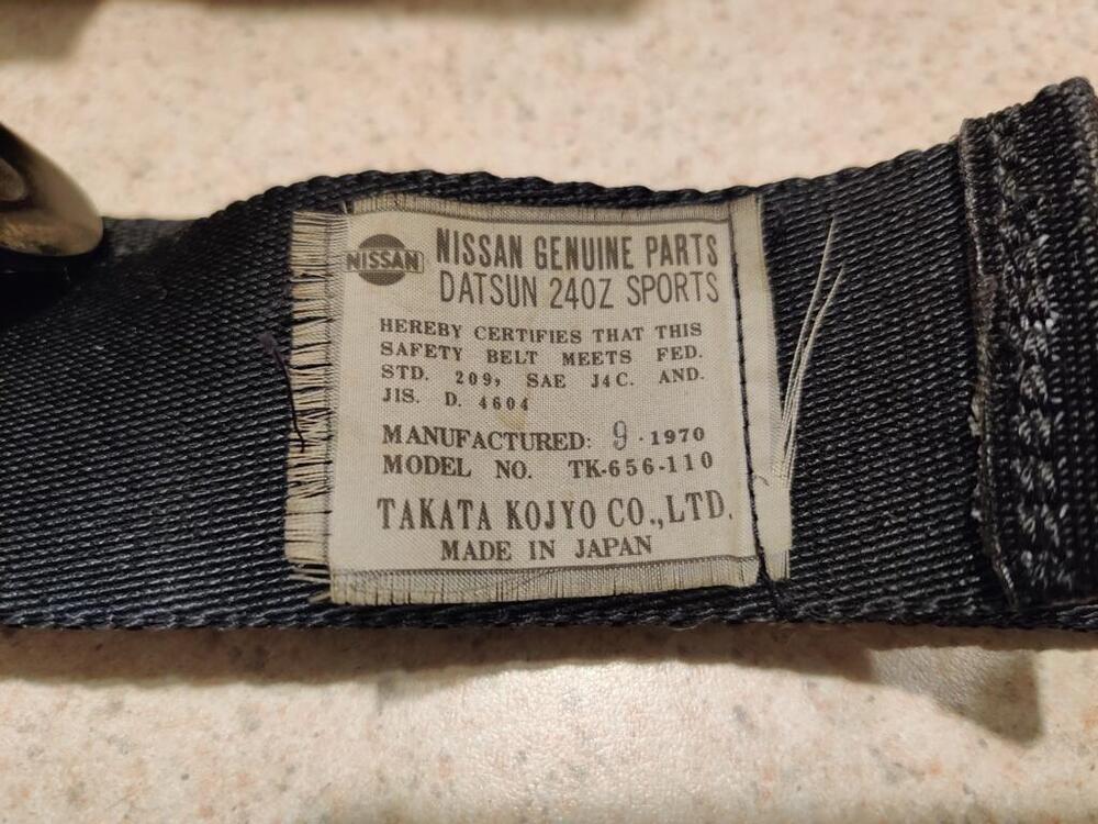
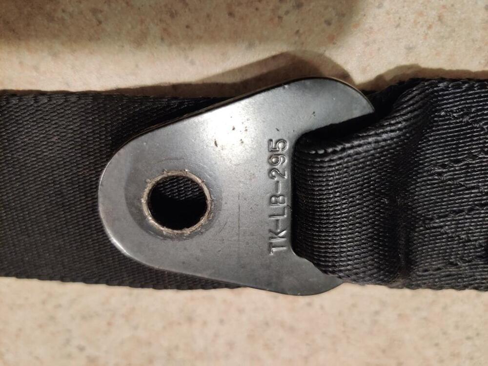
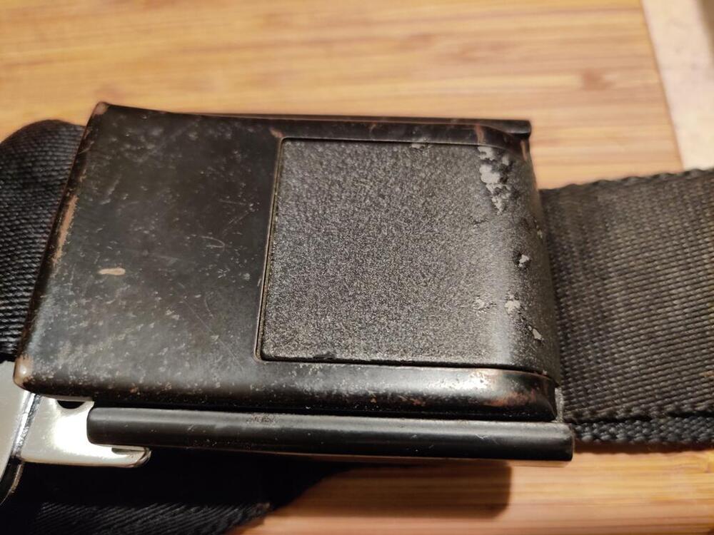
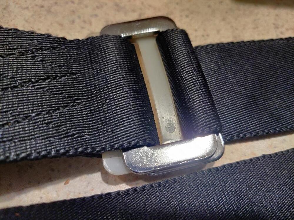
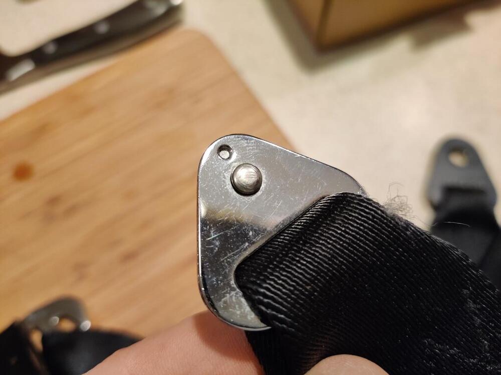
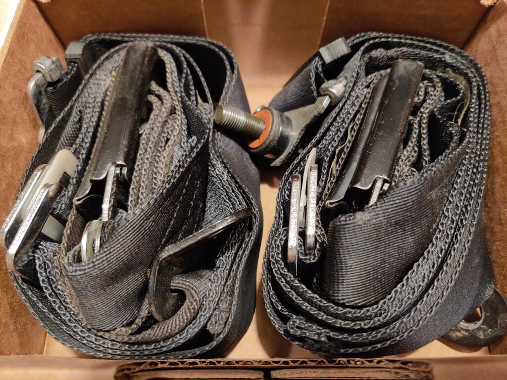
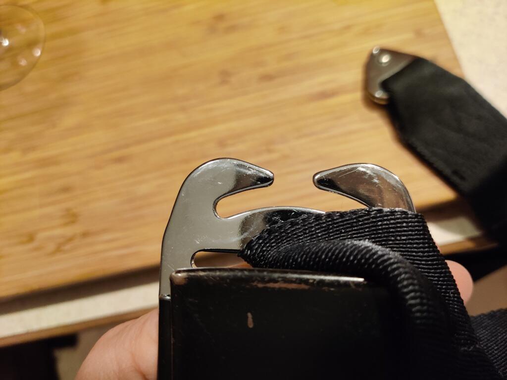
Price for the set is $400 for this complete set of seat belts Complete, original Datsun 240z seat belt set from 9/70 in what appears to be very good condition. The webbing is is excellent condition. Chrome looks very good. Buckles are fully functional. Even mounting hardware is present! PM me with questions, additional picture requests, etc.

 1 point
 -
Cast impeller water pump: https://www.amazon.com/Aisin-WPN-013-Engine-Water-Pump/dp/B008EEZ2XY1 point
-
I would still pull that water pump to see if it has the stamped steel impellers . May have some rusted away or broken as found on some. That would solve most of it if bad. Replace with cast iron type pump.1 point
-
1 point
-
A cloth buffing wheel with fine polish compound on my hand drill. I will show a picture tomorrow. I have a bench mount buffing wheel as well that I use to polish all of the window frames, but the knob is too small for that.1 point
-
1 pointGo buy some taps to figure out your issue. Chances are it’s 1.25. You’re going to need to clean the threads regardless. Don’t try to install a bolt without cleaning almost every thread you run into.1 point
-
The guys with the money, so funny. If they had their way people would have to pay to comment on the cars. The high end BaT car auctions are more like a big money poker game. Who's bluffing who. They don't want to know until the sale is over. https://bringatrailer.com/listing/1971-datsun-240z-345/1 point
-
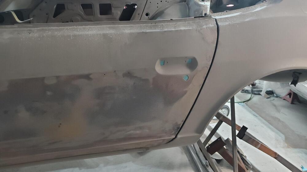
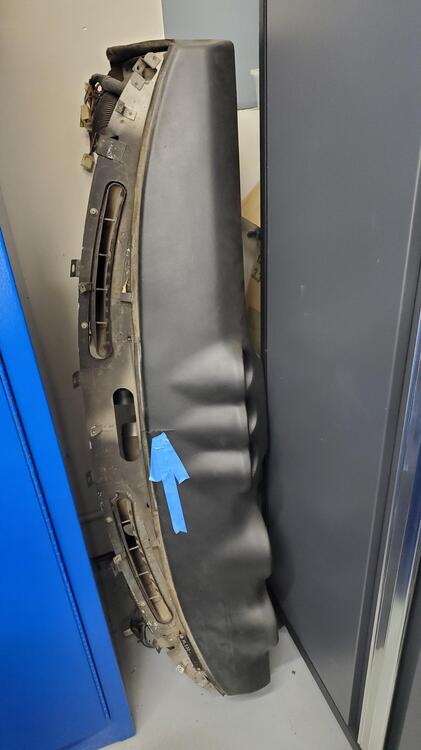
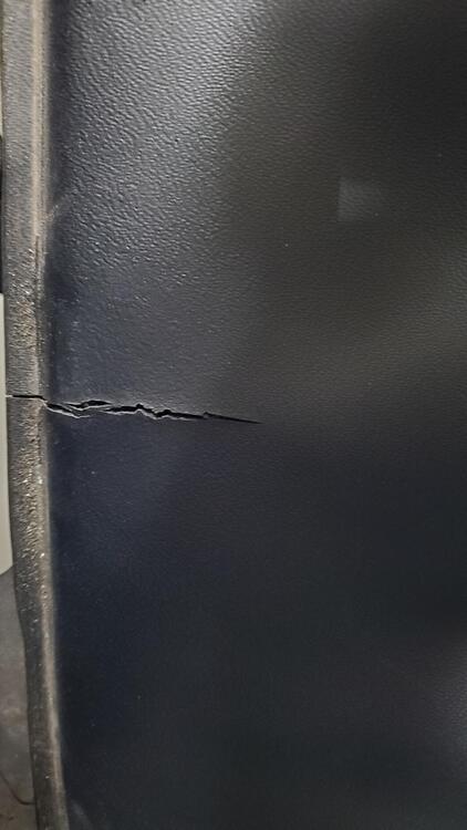
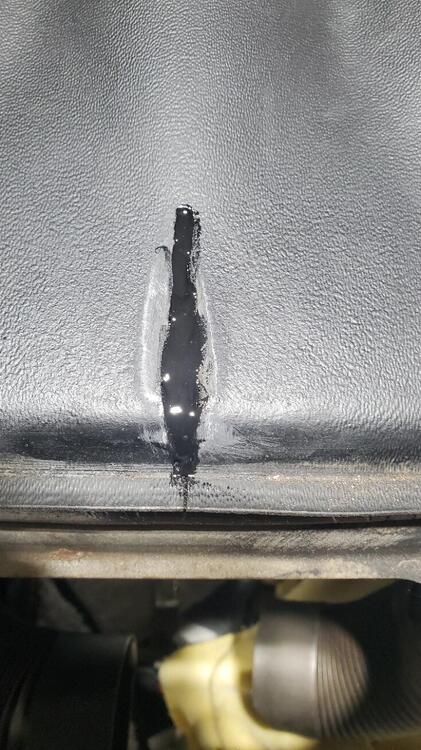
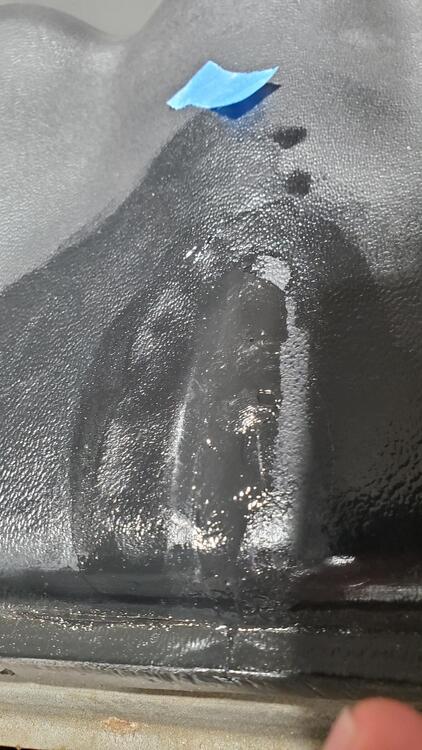
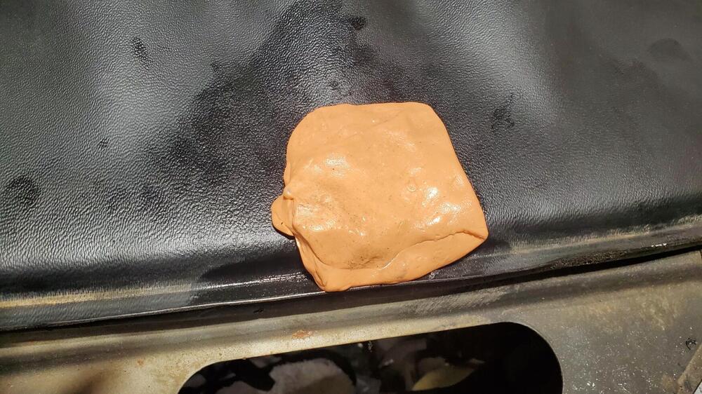
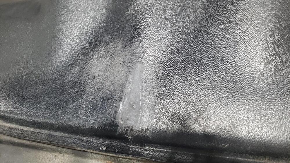
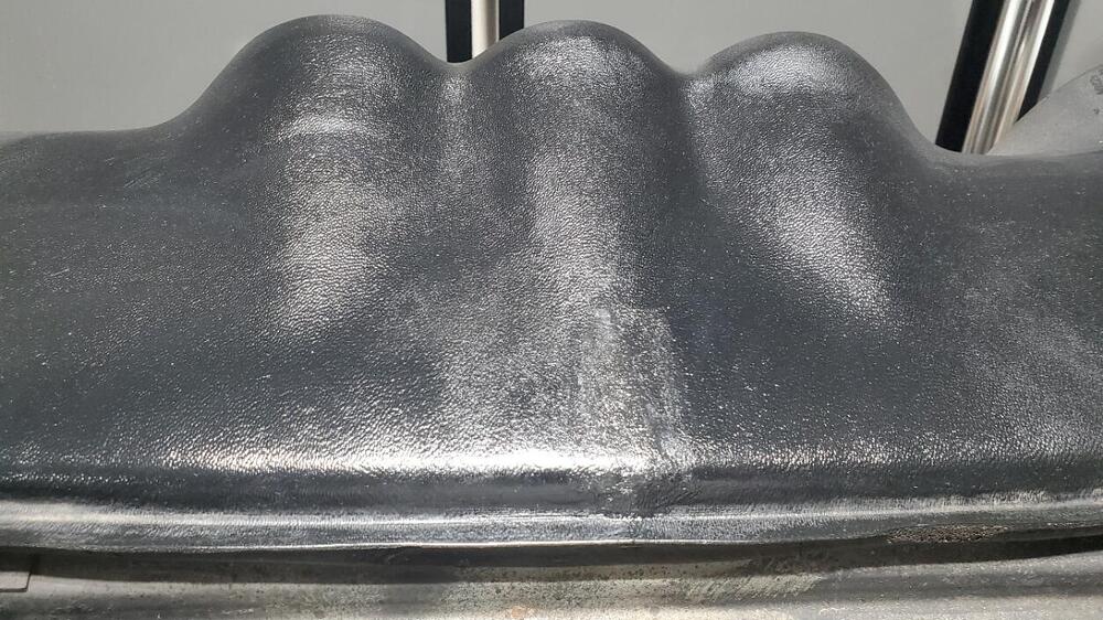
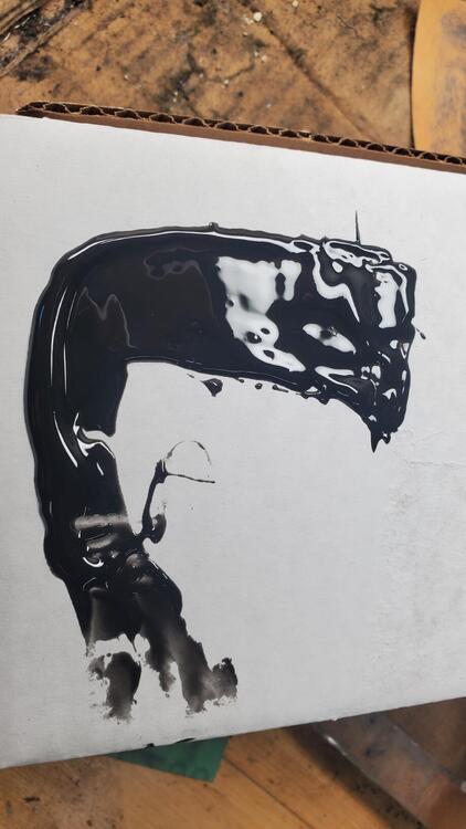
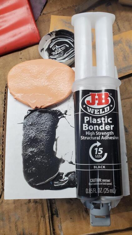
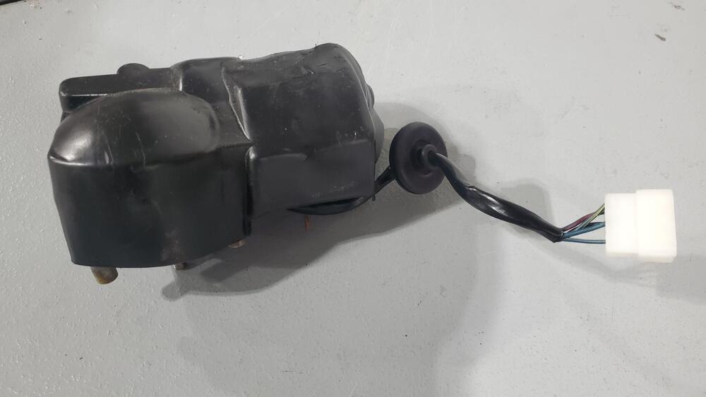
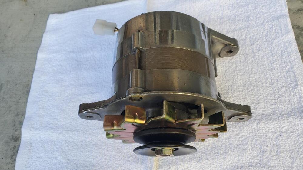
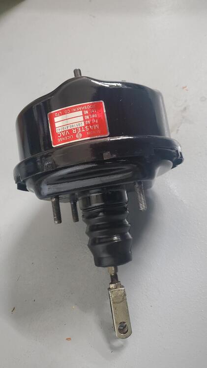
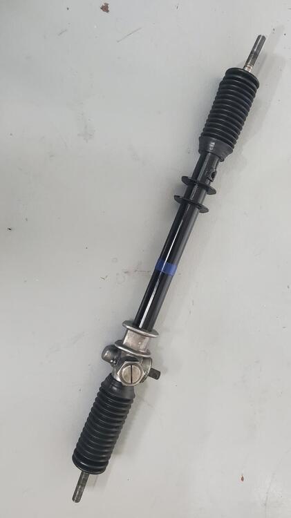
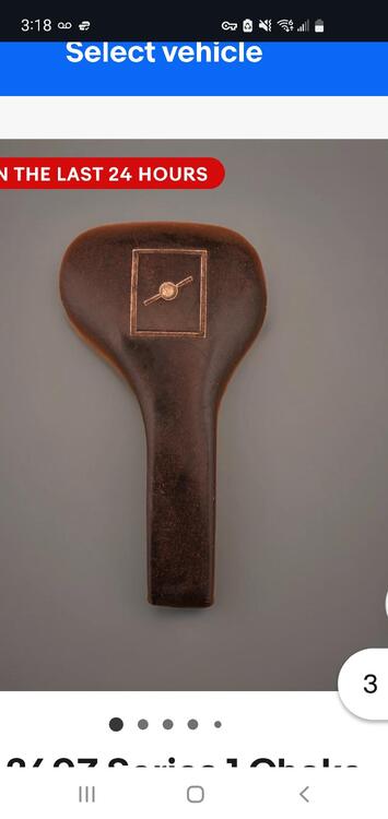
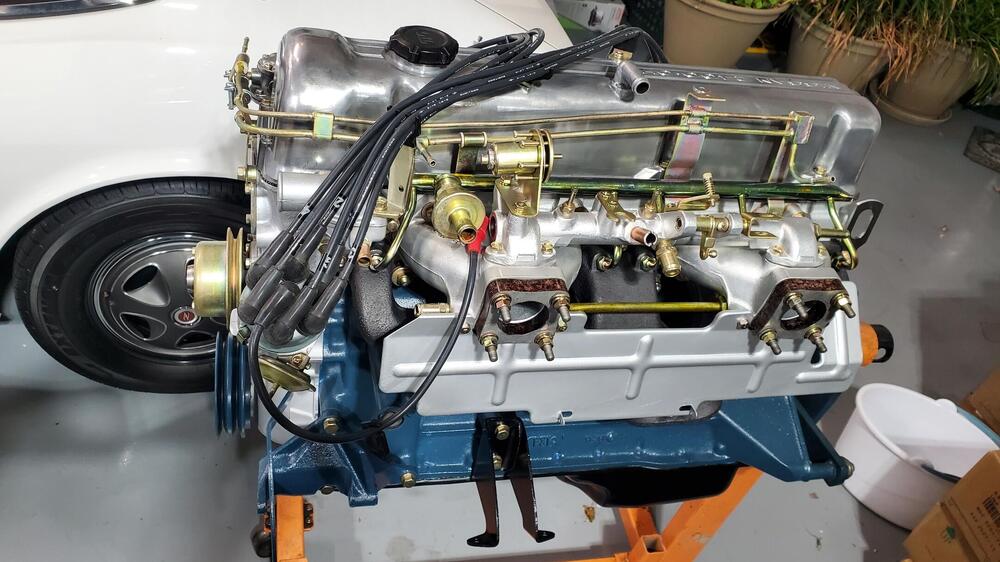
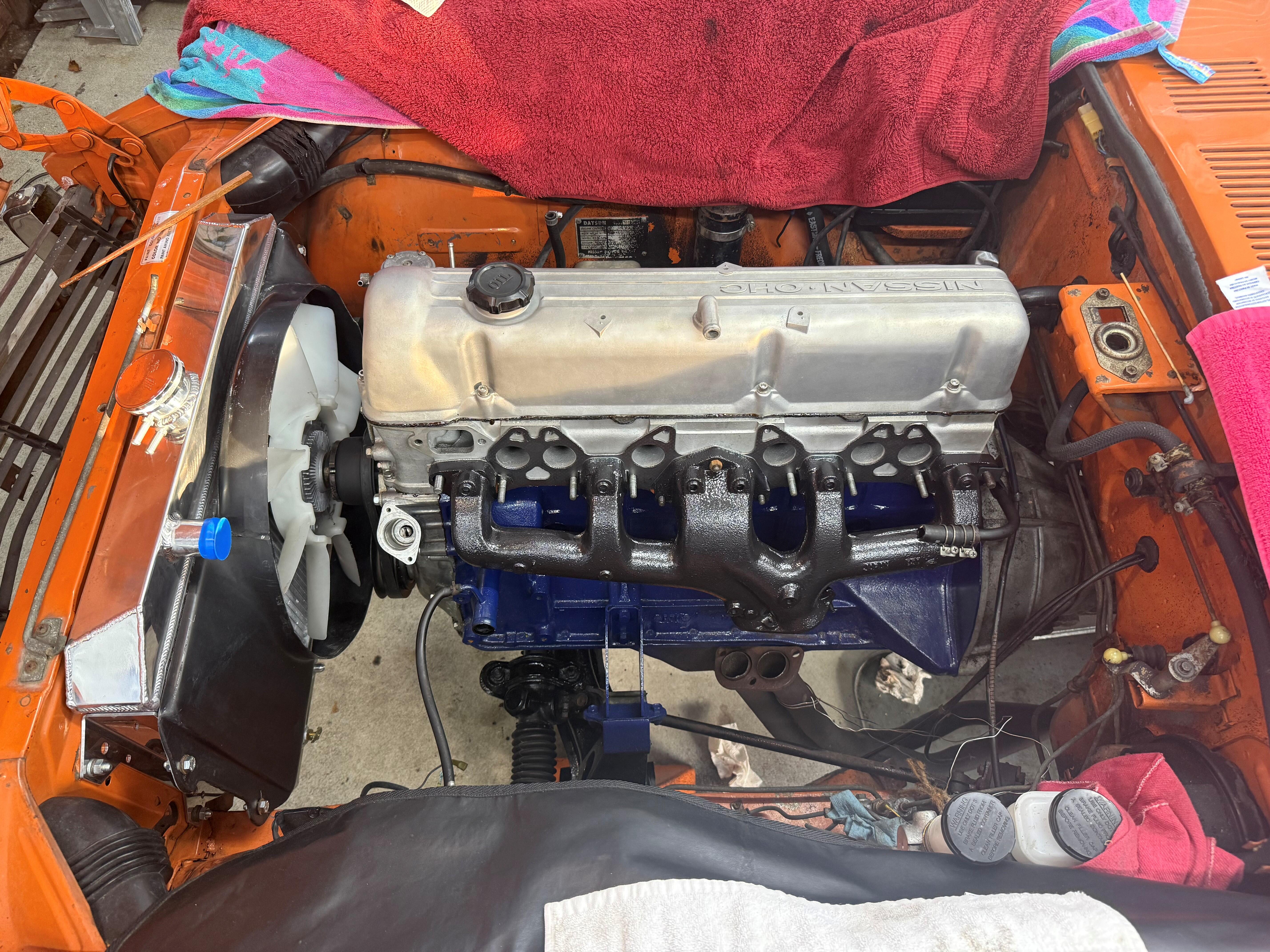
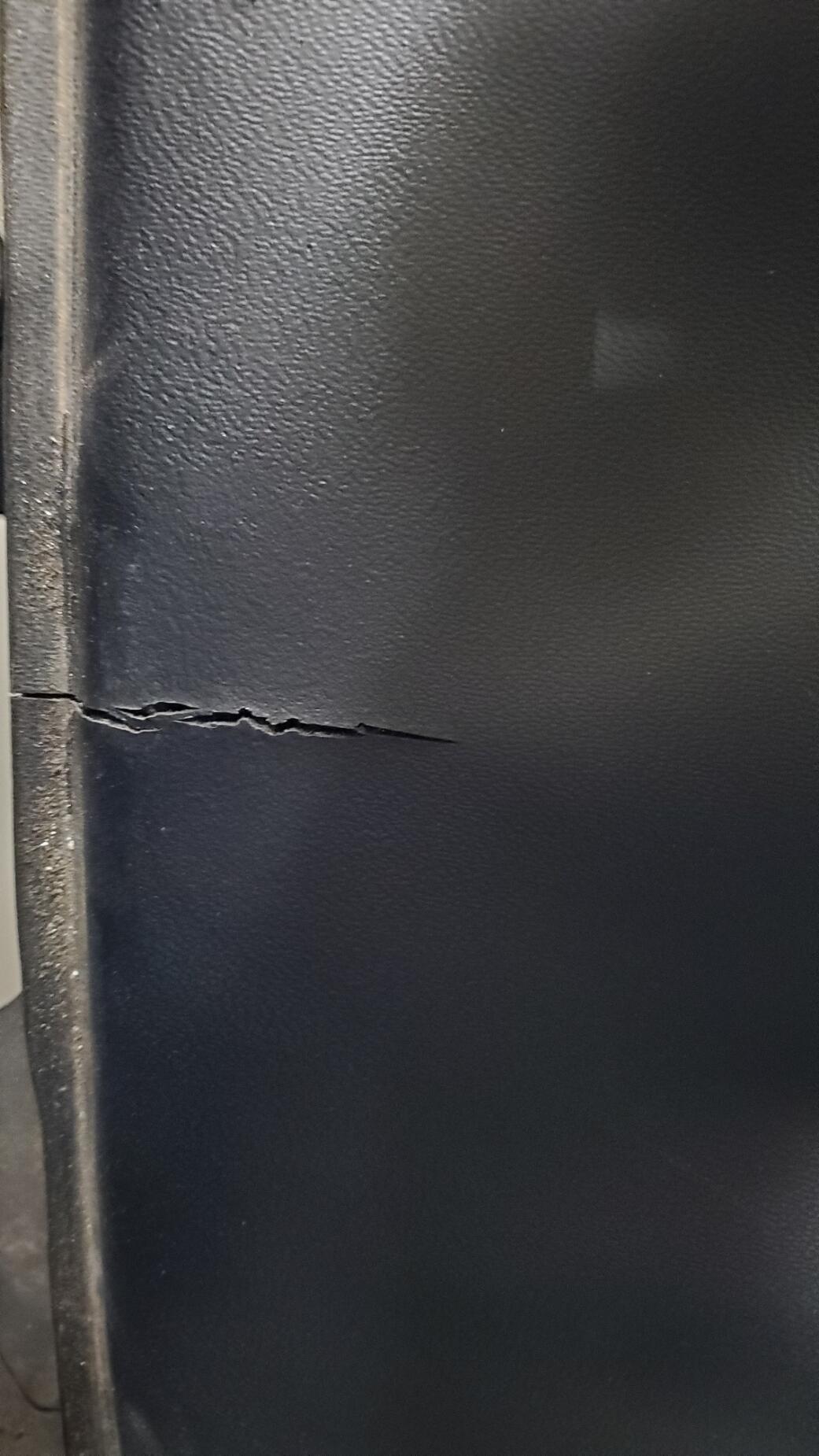
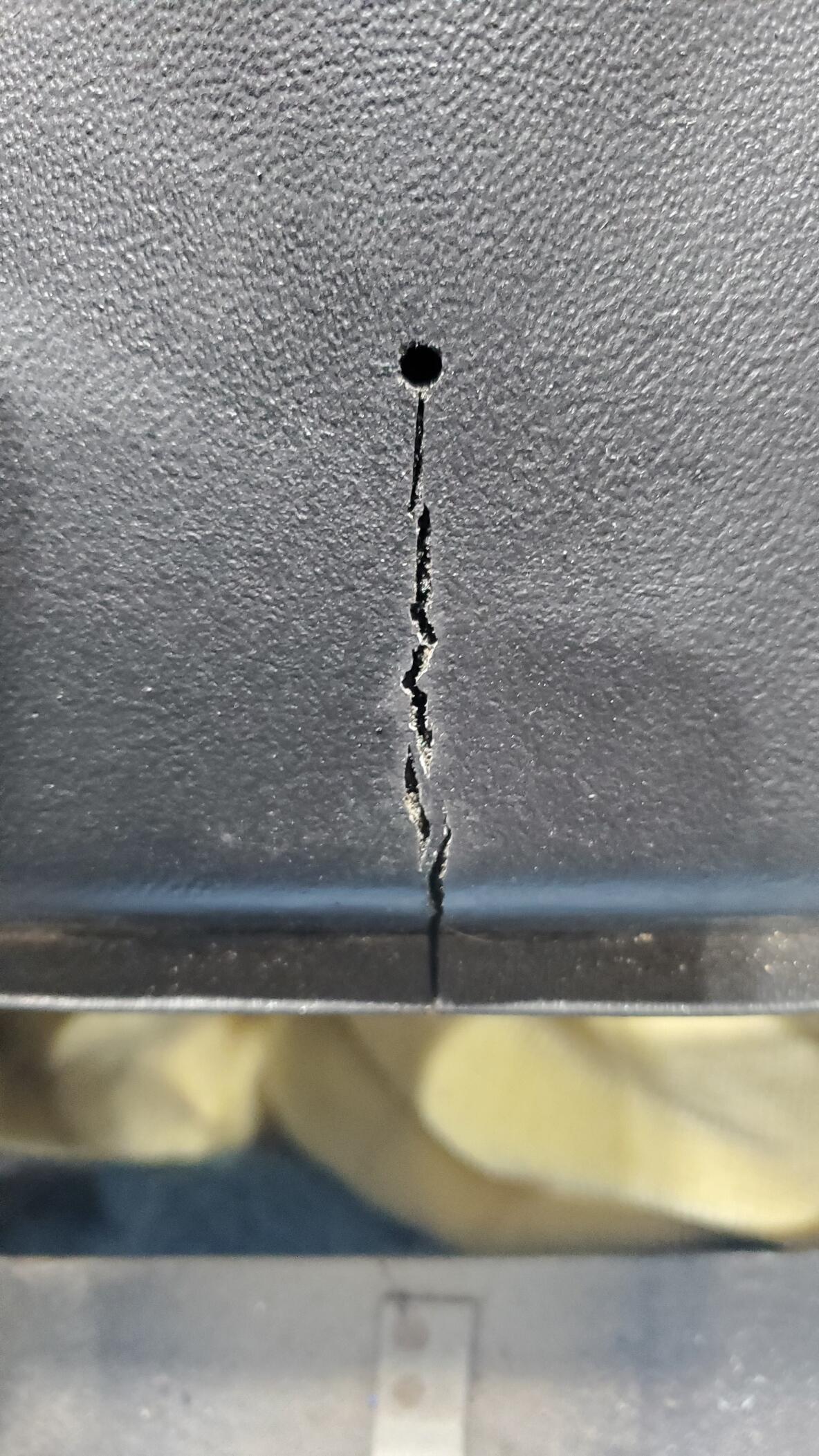
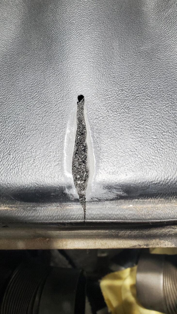
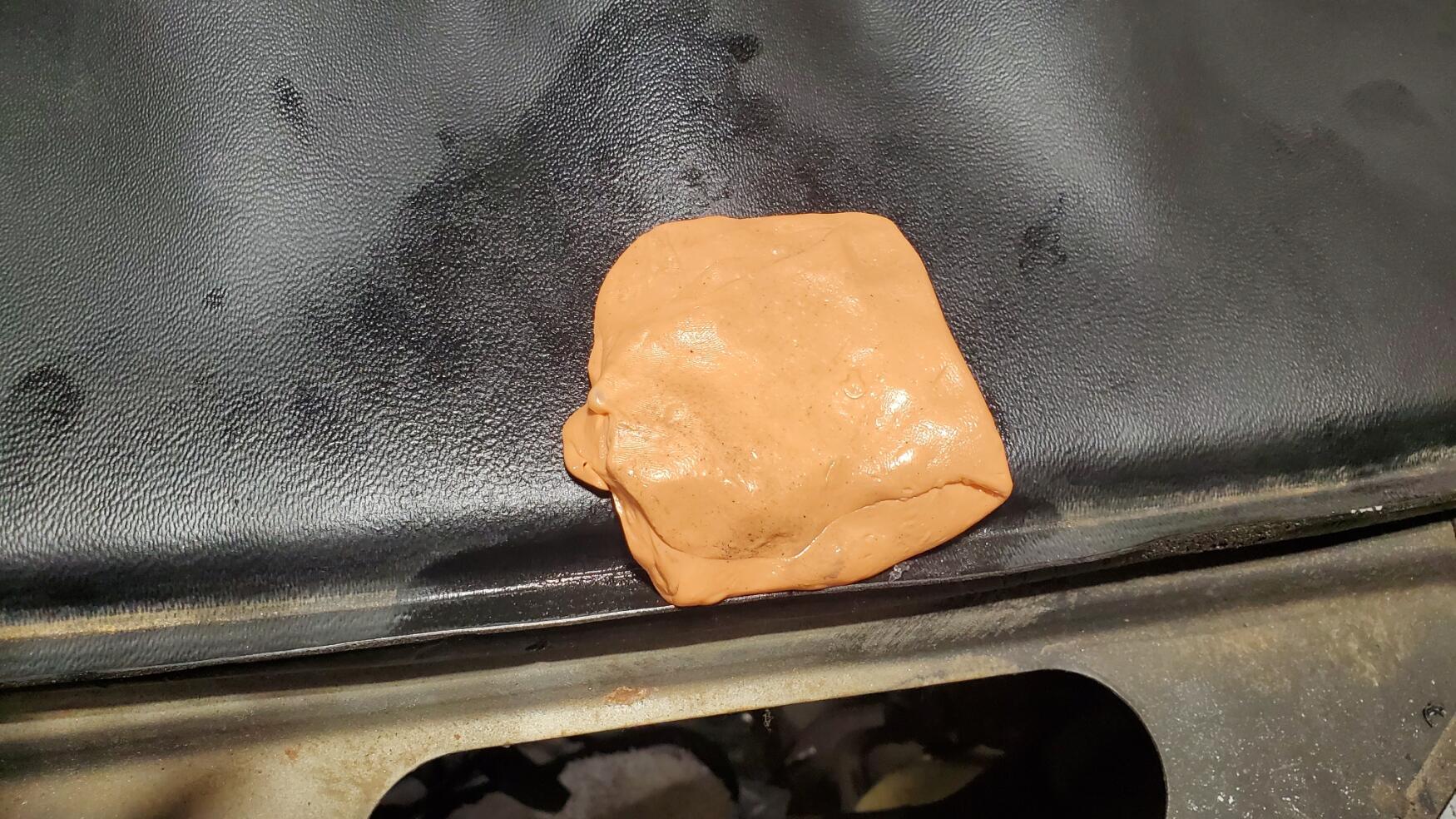
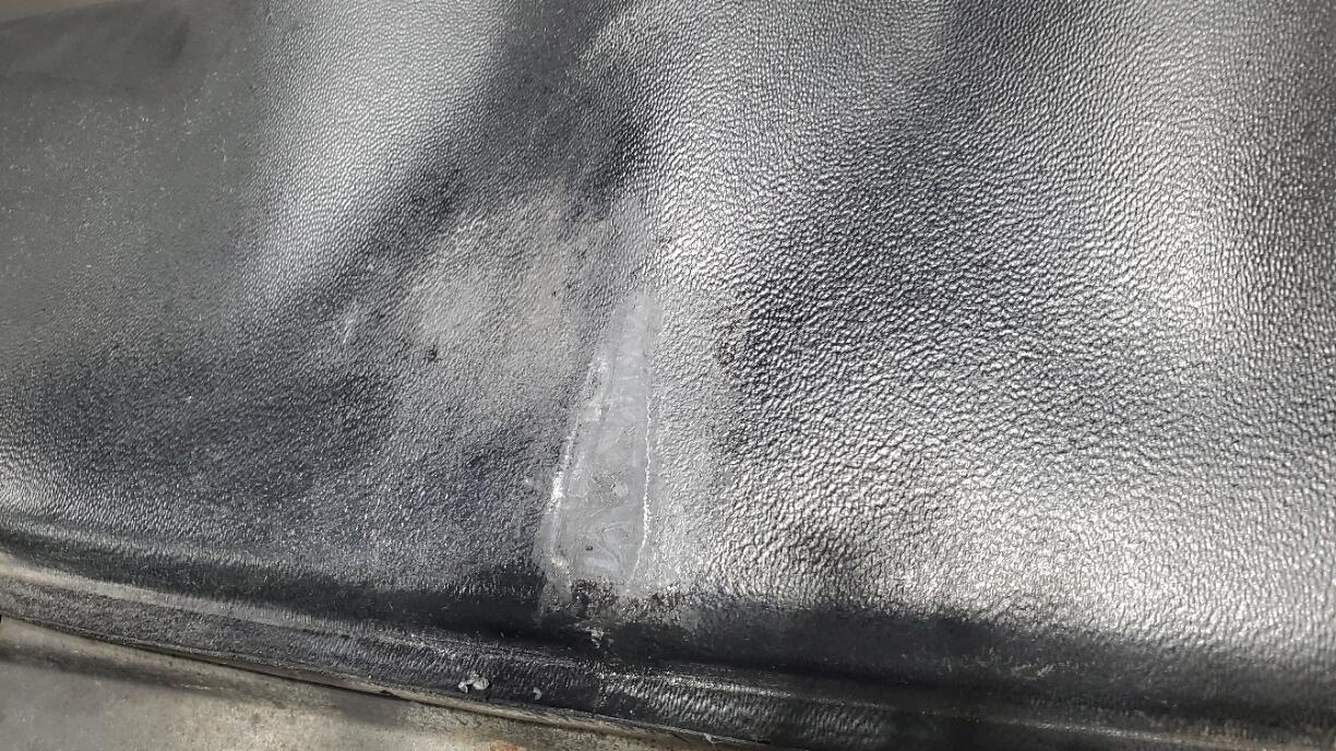
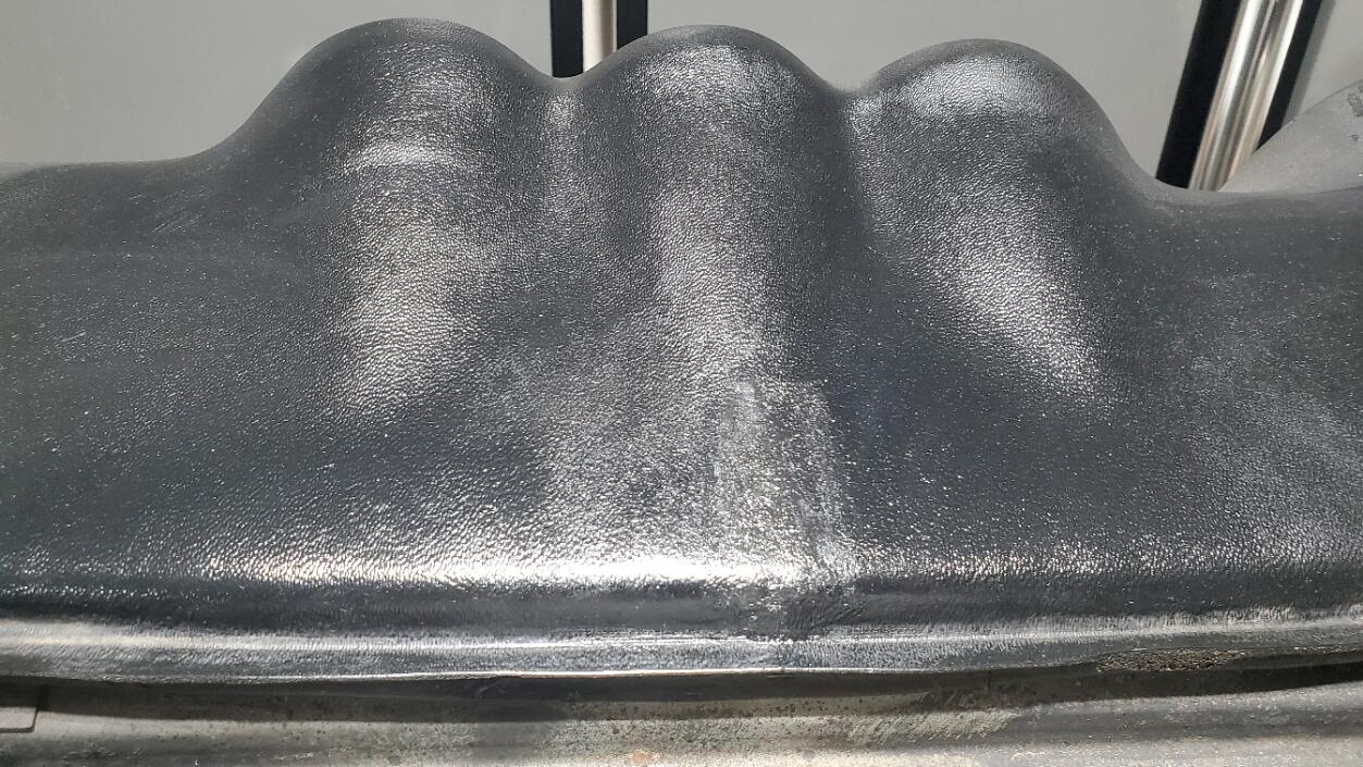
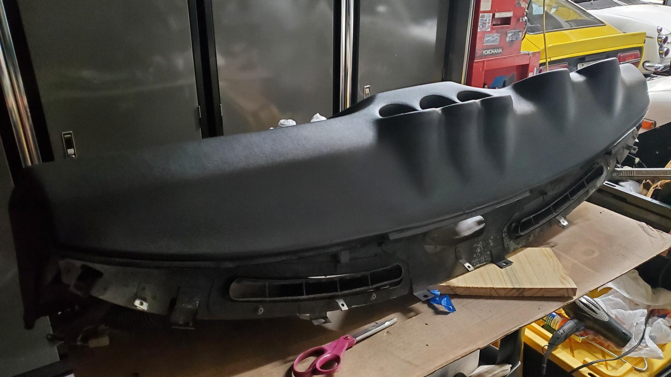
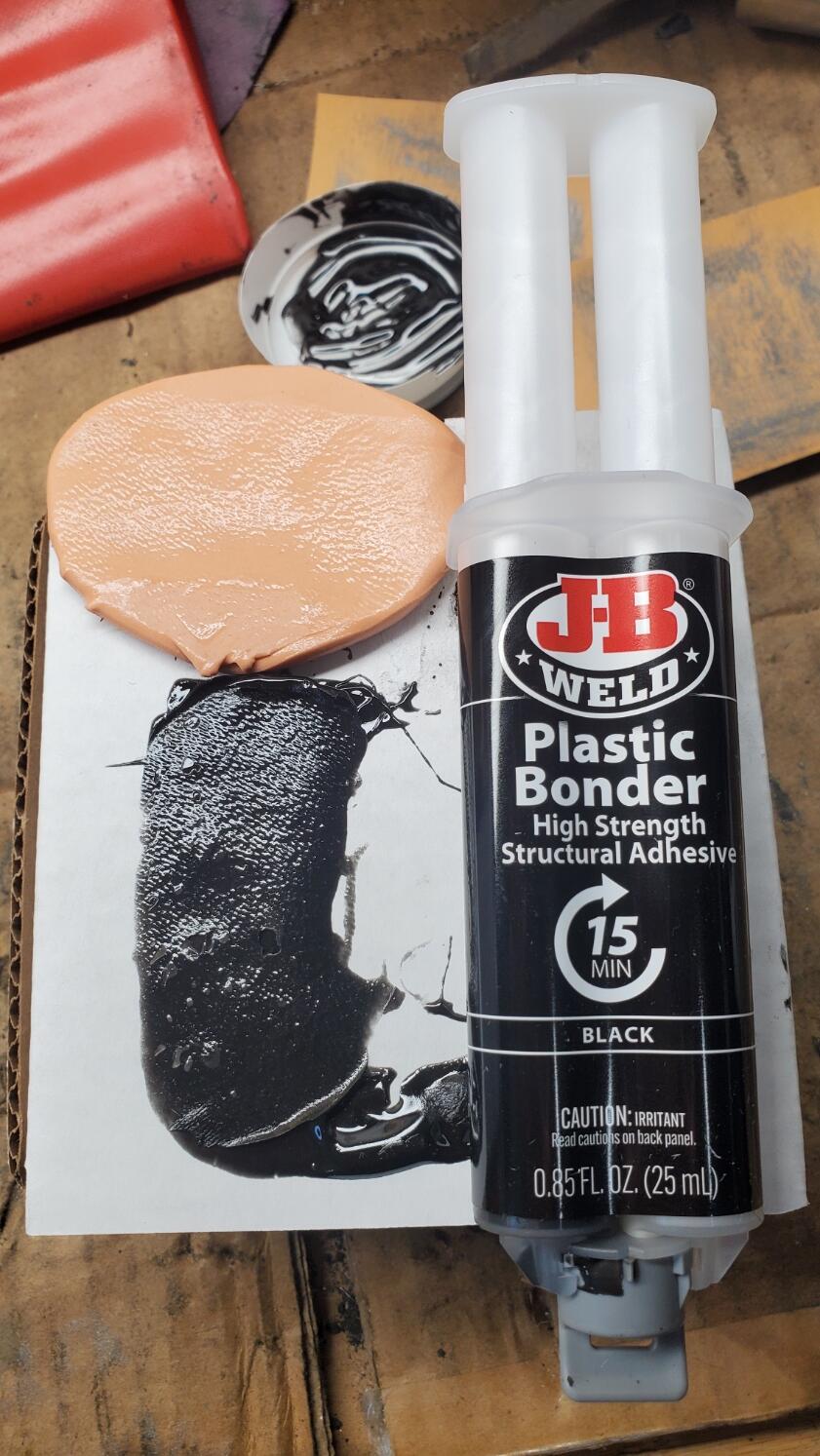
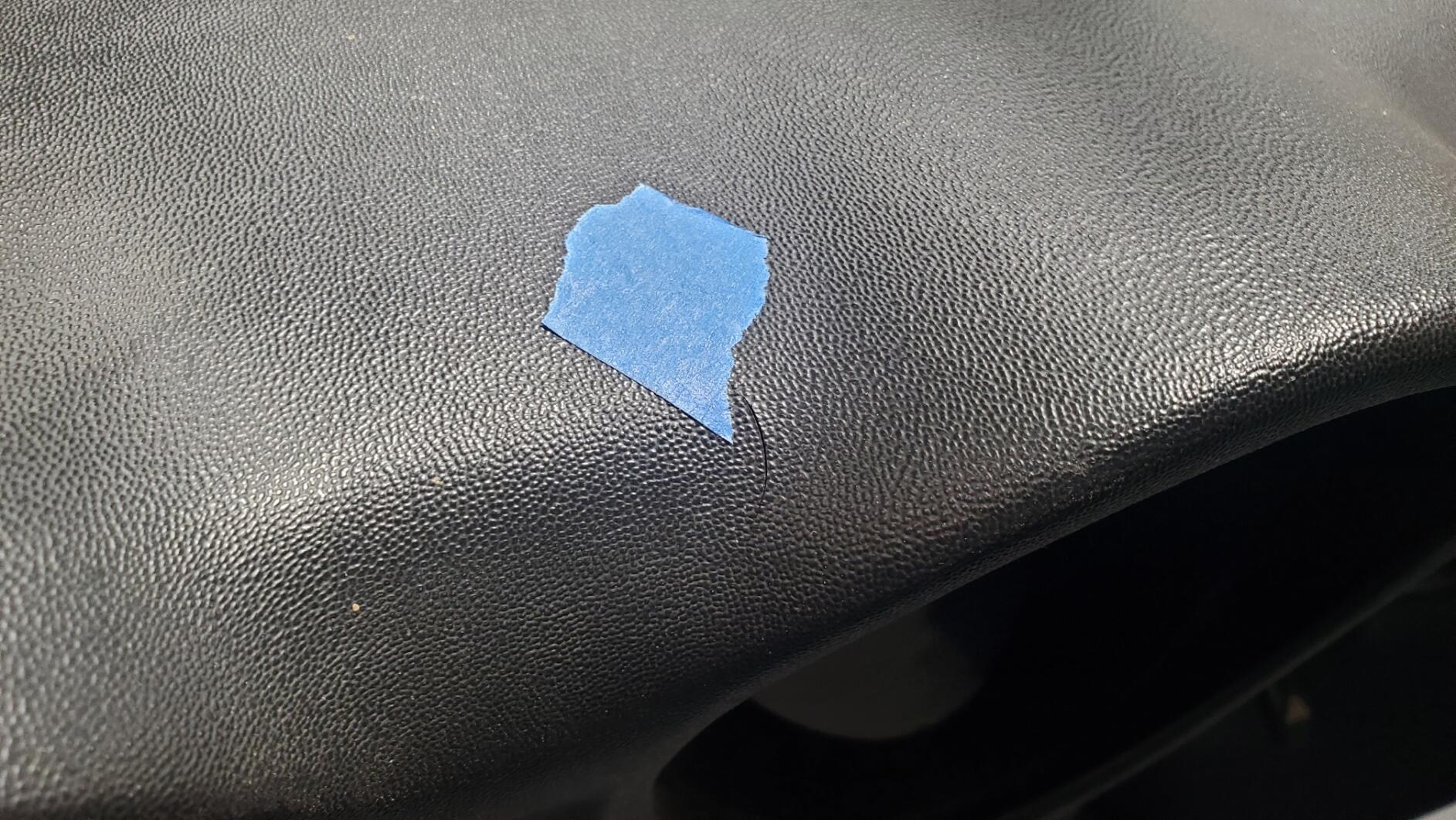
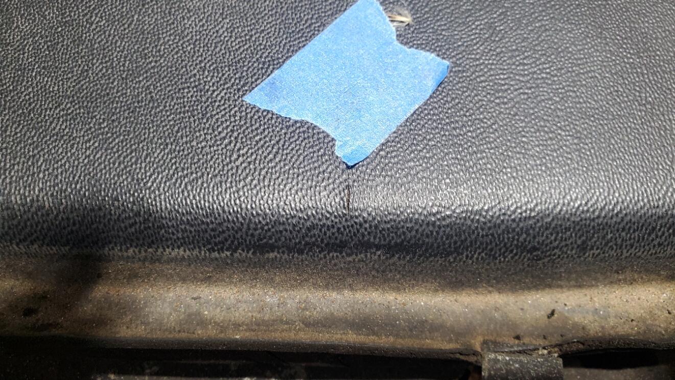
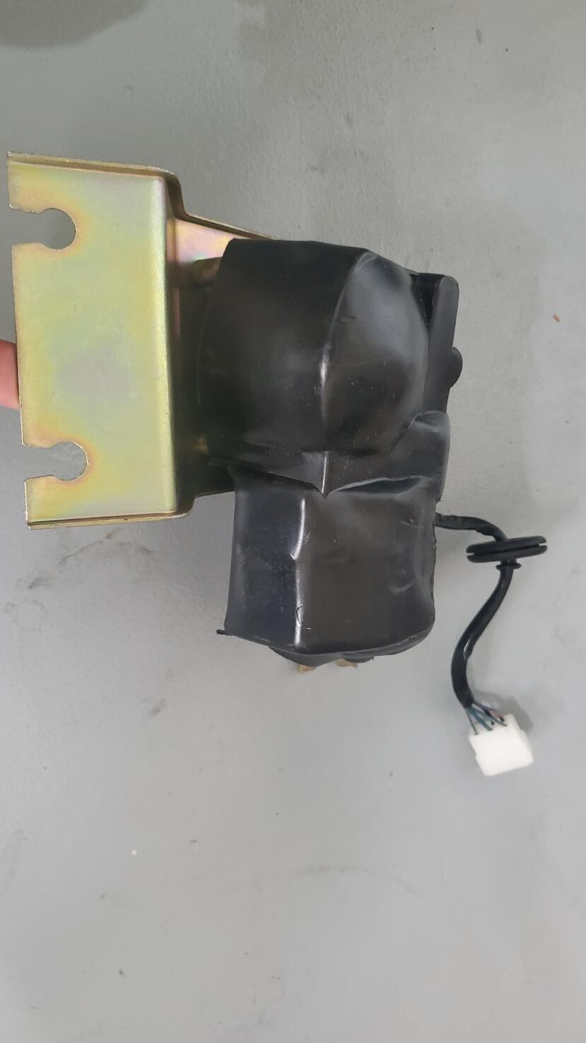
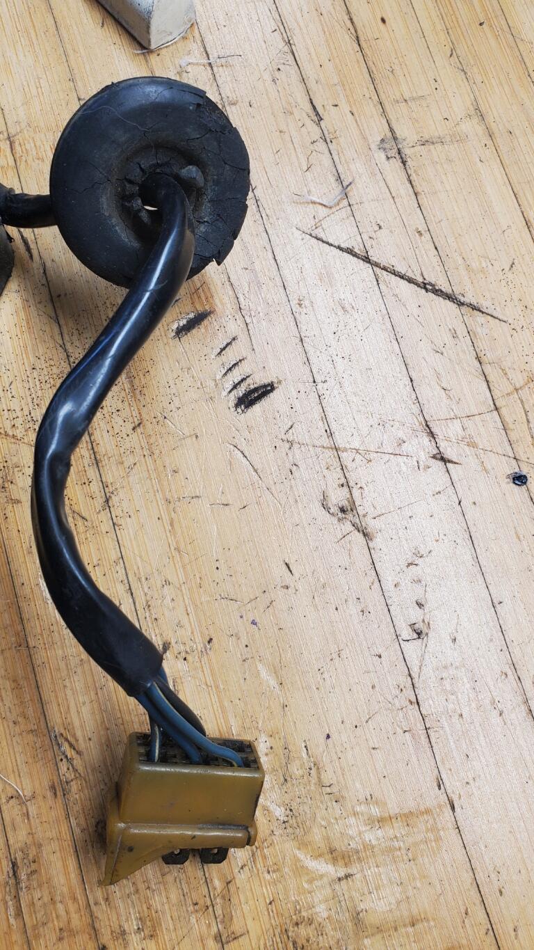
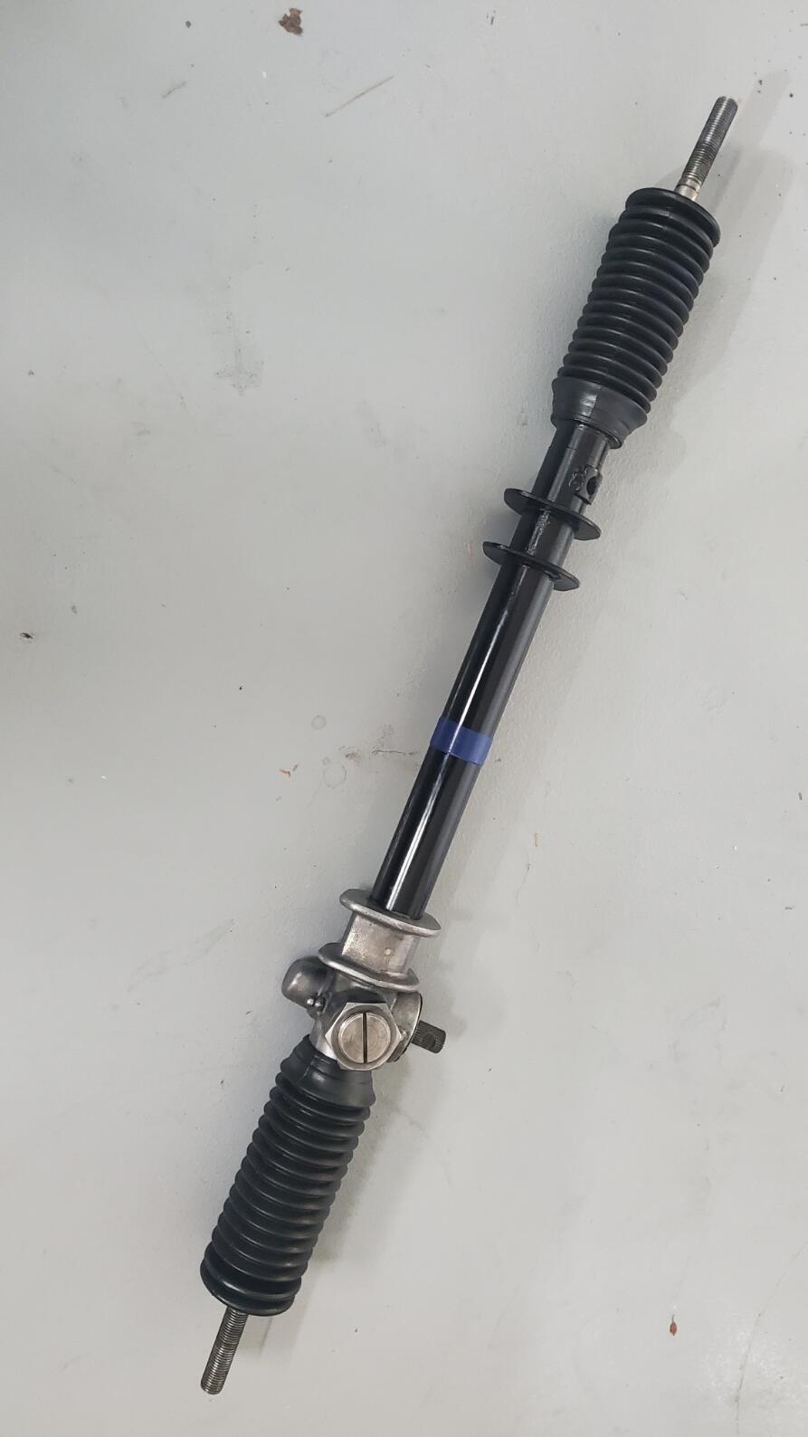
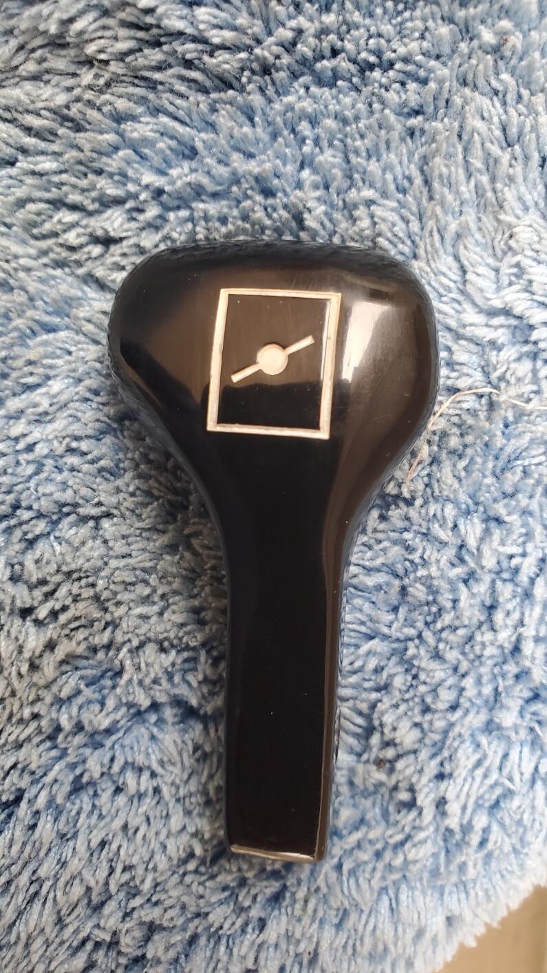
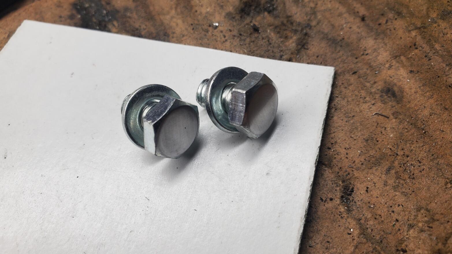
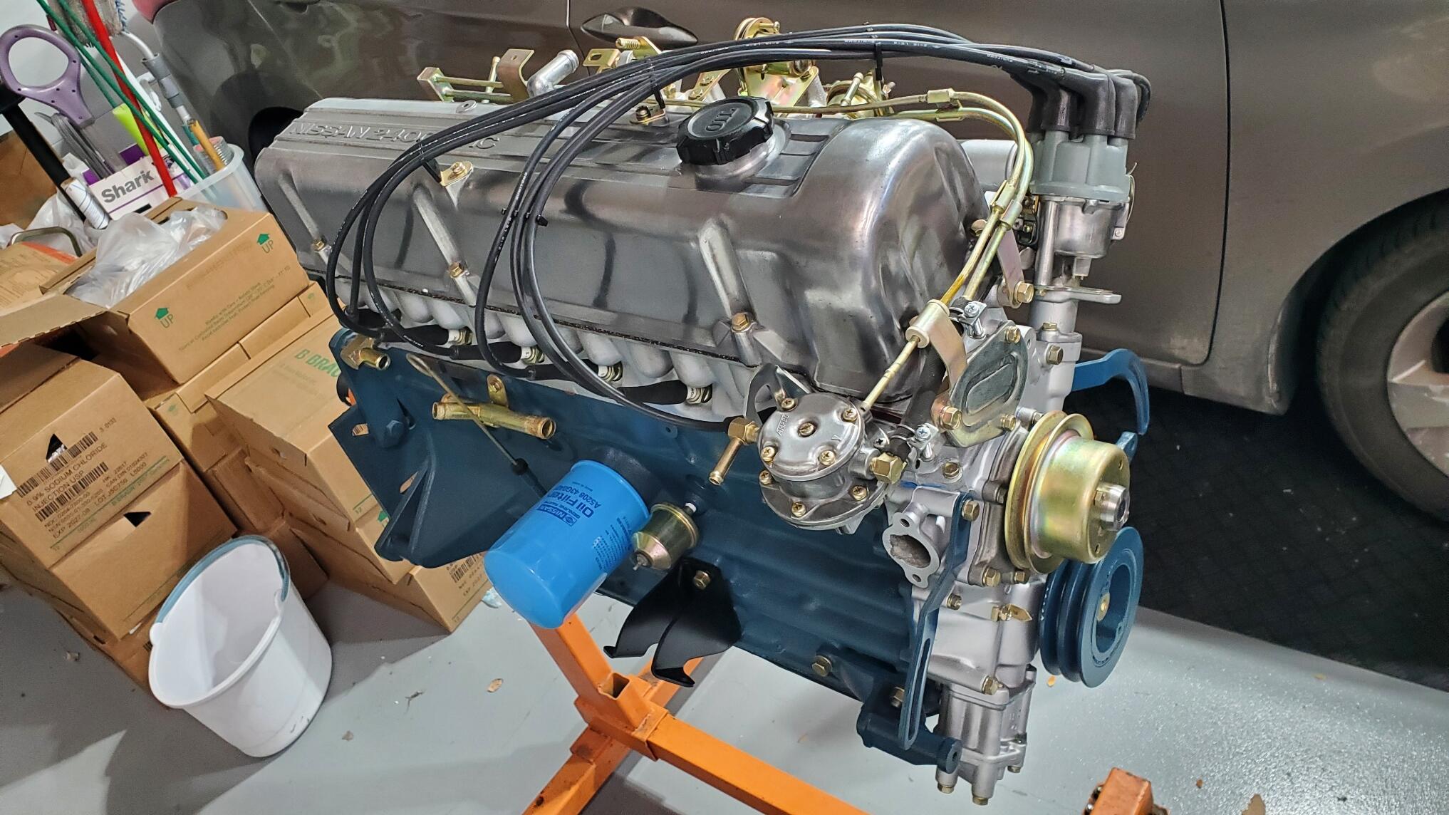
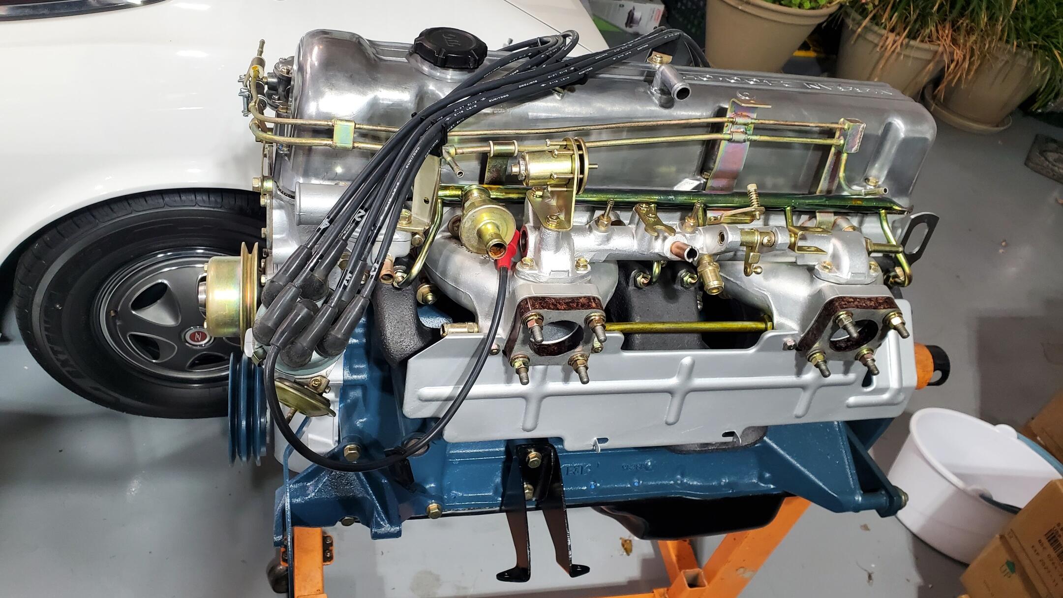
Body work is continuing on the car but at a slower pace than I was hoping. I wanted to get the body back from the shop before Christmas, but I now think it will not arrive until early next year. I will go to the body shop next week and see if I can get a good date on when the car body and paint is expected to be completed. I last went to the shop just before Thankgiving and Carlos was working on getting the door gaps aligned and correct. Still needs some work as the door gap is a bit wide on the drivers side while the passenger side has a mild taper. Latest body shop pictures of the doors is shown below. I looked into getting a local shop that did dash repair work to do the crack repair, but it didn't sound like they could produce what I wanted. Their price was around $400 and they mentioned that 'there would be some scarring left'. I didn't feel comfortable with that and the cost was a bit more than I wanted to pay, so I read up on the dash repair thread here and decided to do it myself. I am actually pretty happy with the final results. It is not perfect, but quite good even under my bright LED shop lighting. In natural light the dash looks perfect. I will try and sequence the process in the pictures below. I used the 'silly putty' technique to match the grain. There were also a couple of small hairline cracks, so I used the plastic epoxy to fill those while I was at it. I am cleaning up other parts as I continue to wait for the body. Below are some of the re-furb pics of the Windshield wiper motor, alternator, brake booster, steering rack and choke knob. All connector housings and most terminals were replaced where needed. FYI: I purchased the steering rack boots from 'Best Parts On-Line' for about $45 including shipping. These are the same ones that zcardepot sells for over $120. Very happy with the fit and feel. On the valve cover, the car arrived with the incorrect bolts that secure the spark plug wire supports. So I replicated the correct style bolts by filing off the top numbers on similar bolts and polishing the head. Thin clear coat on top to prevent rust. Cleaned up the distributor and installed the fuel pump. Not sure about the correct color of the distributor cap, but this green-gray cap was sitting in one of my boxes so I decided to use it. The distributor cap that was installed when car arrived had a cracked tab, so needed replacing. Also, input regarding the correctness of items is appreciated (though not always agreed upon). Items like the correct bolts for the valve cover plug wire supports were pointed out via PM and the item corrected. Thanks!


 1 point
 -
1 pointThats not vapor lock. Different issue entirely Depends how high it climbs on whether its an issue or not. Lots of things can contribute to not being able to shed heat.1 point1 point1 pointIt wasn't meant to be a link, just an abbreviation. Something in the browser or forum software does that automatically, I think. ithink.com link.com thislinkwontwork.com
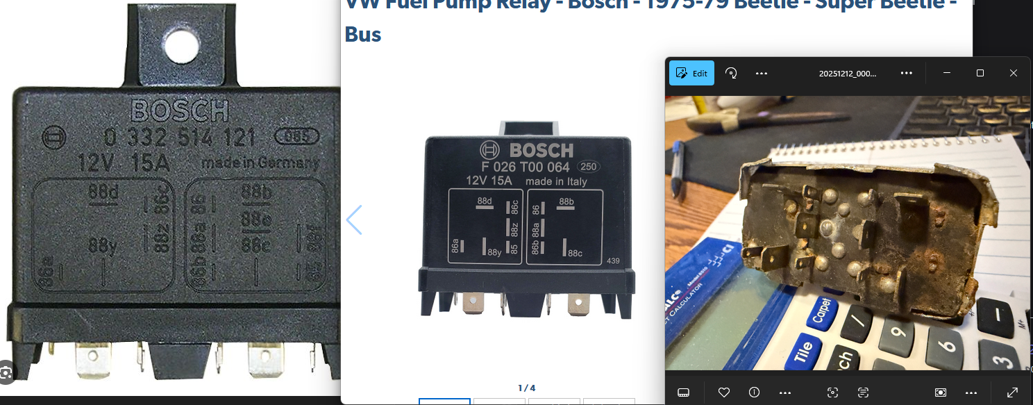
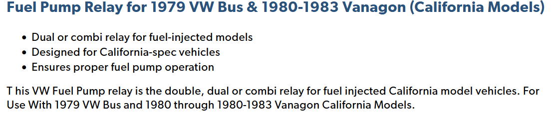
 1 point1 pointThis (F 026 T00 064) was the one I ordered, I got impulsive and this was the first part number I came across from this post here from @SteveJ . I couldnt find any other posts on here with the other part number at the time. The 0 332 514 121 relay has extra pins, this is because the extra pins are for the california vehicles, at least according to Jbugs. I suspect that using that relay is just fine since the car doesnt need those pins. This is the description for bosch relay 0332 514 121 accordinng to Jbugs BTW @Zed Head That CZCC link doesnt work
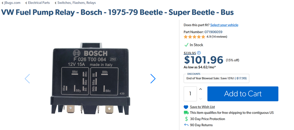
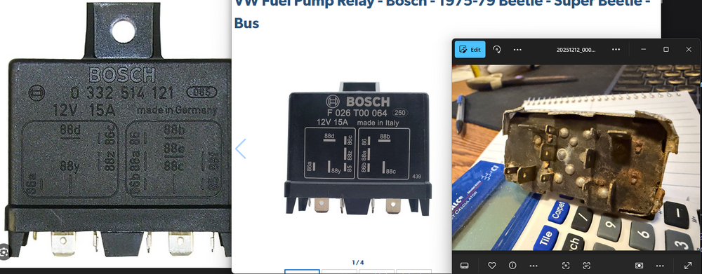
 1 point1 pointEFI/pump relay. Which one did you order? You didn't say. Don't overlook that the pump relay is controlled by the switch in the AFM. And that there is no "prime" like on today's vehicles. The pump relay is energized by the AFM switch or when the key is at Start.1 point1 pointWhile it looks nice and will make a good starting point why was the color changed to a non Datsun Z car color? The late Paul Taylor's 240 has emerged from the shadows and is for sale @ Carolina Muscle Cars for 125K.
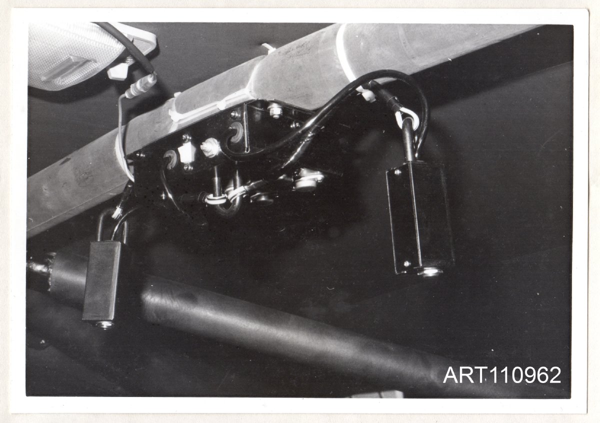
.thumb.JPG.abbc8b0ddcb3956dd3861a263e22ba12.JPG) 1 point1 pointHopefully not too much of a digression, but here's a photo of another iteration of the Teikoku Dempa/Clarion intercom/interphone box. This is an original period photo from a small hand-made booklet of data and advice put together by Nissan's Works competitions department at Oppama, and sent to the de-facto competitions department here in the UK in May 1974 (by then based at Nissan UK's Worthing HQ) with the intention of informing the UK competitions staff about details of the new P710 'Violet' Works rally cars which were - at that point - being shipped to them. The intercom/interphone unit is very similar to the one seen on '7924', which was built in mid 1972. It has the same volume control (interestingly, for a 'new' and supposedly unused car, the control knob appears to be missing as it is on '7924', which makes me wonder if they were prone to falling off, or just not fitted...?) and it also has the external 'floating' jack boxes, but with some extra belt-and-braces suspension for them. So, an indication that the Works team carried on with the same basic design well into 1974. I guess that Teikoku Dempa must have made a fair few of them?
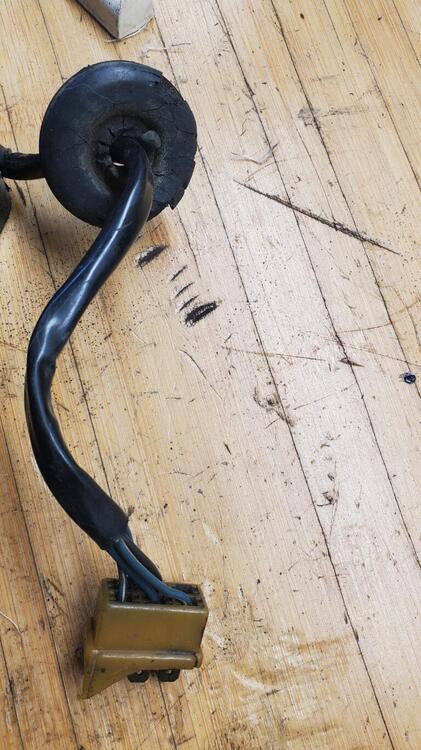
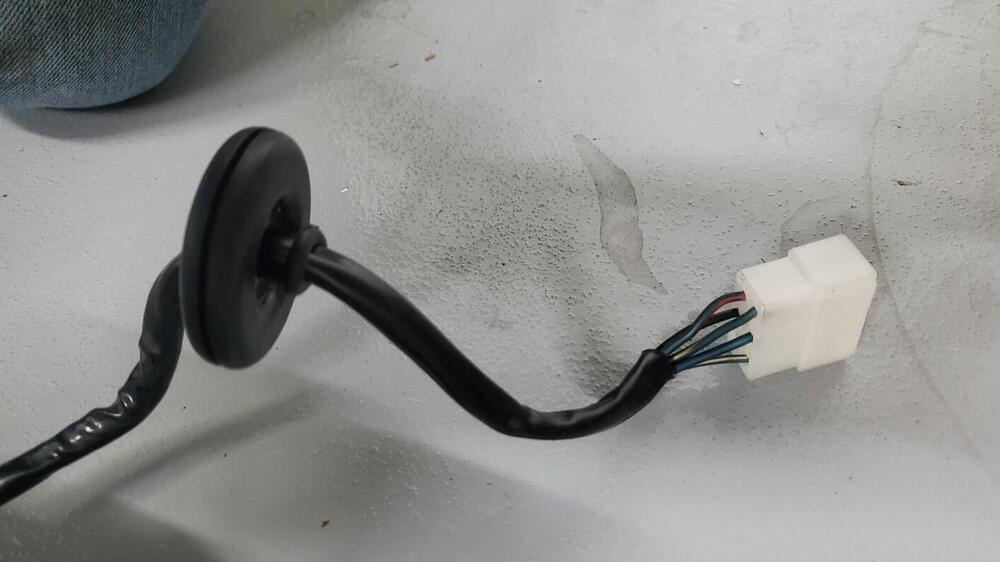
1 point1 pointHopefully not too much of a digression, but here's a photo of another iteration of the Teikoku Dempa/Clarion intercom/interphone box. This is an original period photo from a small hand-made booklet of data and advice put together by Nissan's Works competitions department at Oppama, and sent to the de-facto competitions department here in the UK in May 1974 (by then based at Nissan UK's Worthing HQ) with the intention of informing the UK competitions staff about details of the new P710 'Violet' Works rally cars which were - at that point - being shipped to them. The intercom/interphone unit is very similar to the one seen on '7924', which was built in mid 1972. It has the same volume control (interestingly, for a 'new' and supposedly unused car, the control knob appears to be missing as it is on '7924', which makes me wonder if they were prone to falling off, or just not fitted...?) and it also has the external 'floating' jack boxes, but with some extra belt-and-braces suspension for them. So, an indication that the Works team carried on with the same basic design well into 1974. I guess that Teikoku Dempa must have made a fair few of them? 1 pointOkay, the body harness has been stripped. I am very glad I didn’t try to use this thing. It’s melted / burnt in two places and has been messed with and rewrapped in three places. The next step is to compare this to the diagram and see what the story is.
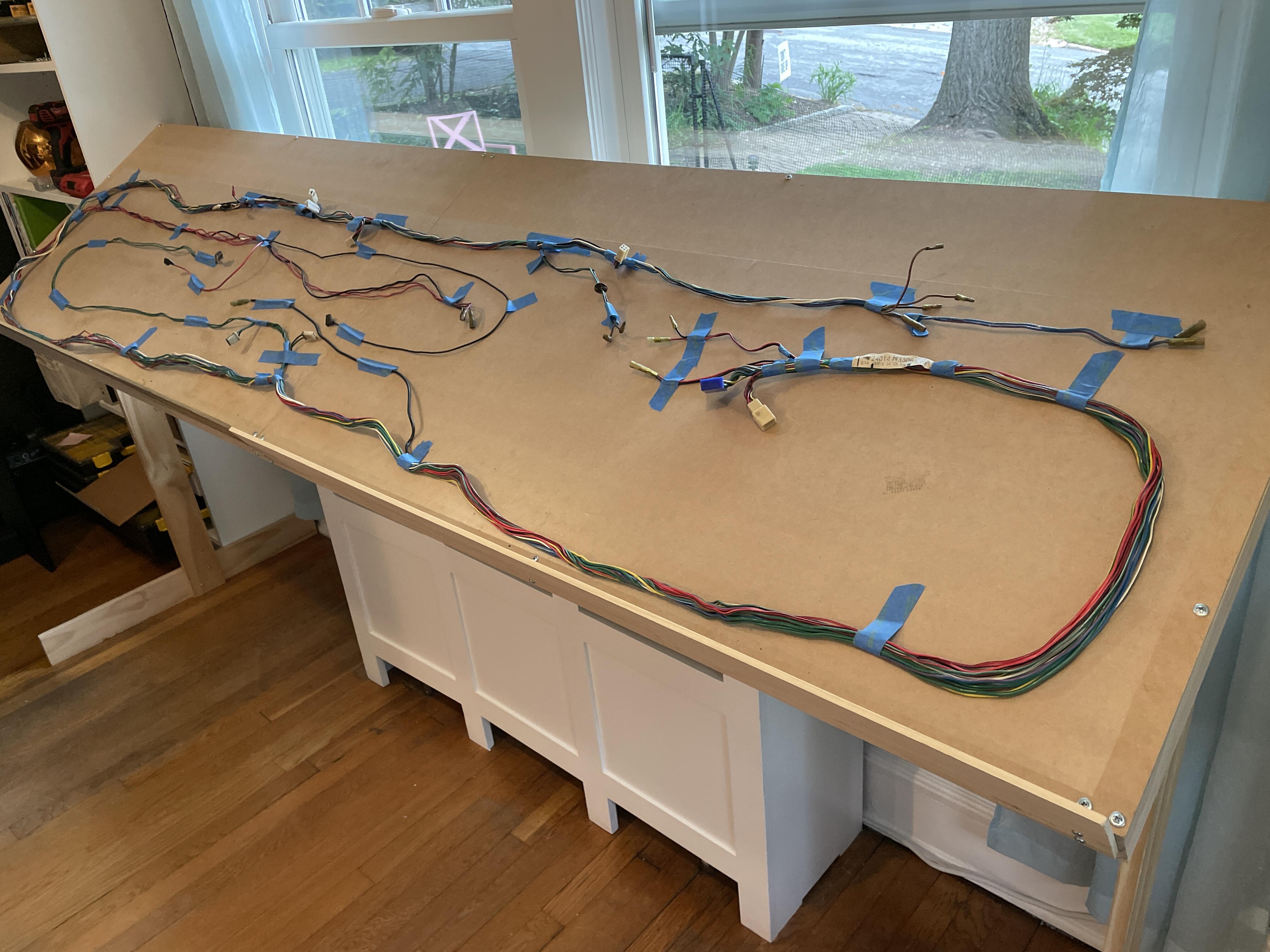
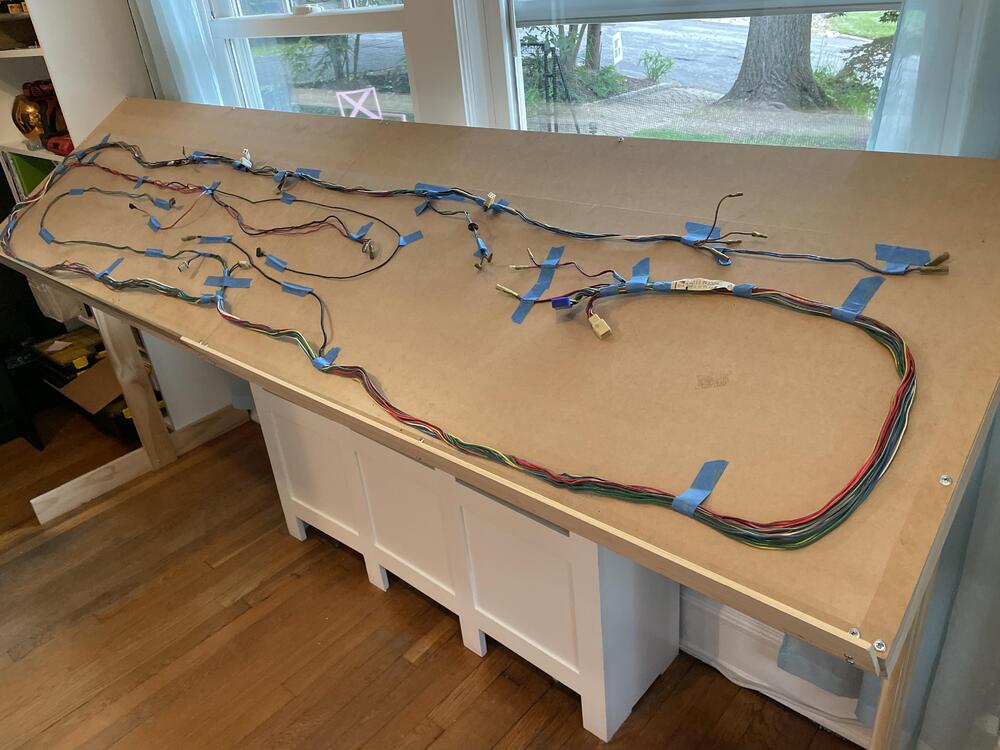 1 point


.JPG.259cfca933974fce5b0ed2f6a7e6803c.JPG)


Important Information
By using this site, you agree to our Privacy Policy and Guidelines. We have placed cookies on your device to help make this website better. You can adjust your cookie settings, otherwise we'll assume you're okay to continue.