Leaderboard
-
conedodger
Community Member28Points13875Posts -
Seppi72
Supporting Member10Points455Posts -
DrFeelGood
Community Member6Points69Posts -
Captain Obvious
Community Member5Points10265Posts



Popular Content
Showing content with the highest reputation since 10/02/26 in all areas
-
3 pointsBroken bolts fix. Ended up being able to remove both the broken drill bit and the easy-out. Decided to finish drilling out the stuck bolts and tap a M12x1.25 (original bolt was a M10x1.25). Had to enlarge the bolt holes in the link mount brace to 1/2 inch so everything aligned. Suspension back in place. Thanks to everyone for the support.3 points
-
I bought a hand-operated transfer pump so I shouldn't have any trouble putting in the 1.5 L of Redline MT-90 when the engine and tranny assembly is firmly bolted into the chassis. Thanks, all, for the warning about tranny tail leakage as it's not mentioned in the FSM that I have.3 points
-
The alternator came with an 800 number to call and unbelievably someone answered right away on a Saturday afternoon. He said the 2-pin readings were normal but the power pole resistance to ground meant it had a problem. Said send it back to z store.3 points
-
I wouldn’t advise filling the trans before installation. Plenty of opportunity to do that while putting the cross member and shaft in.3 points
-
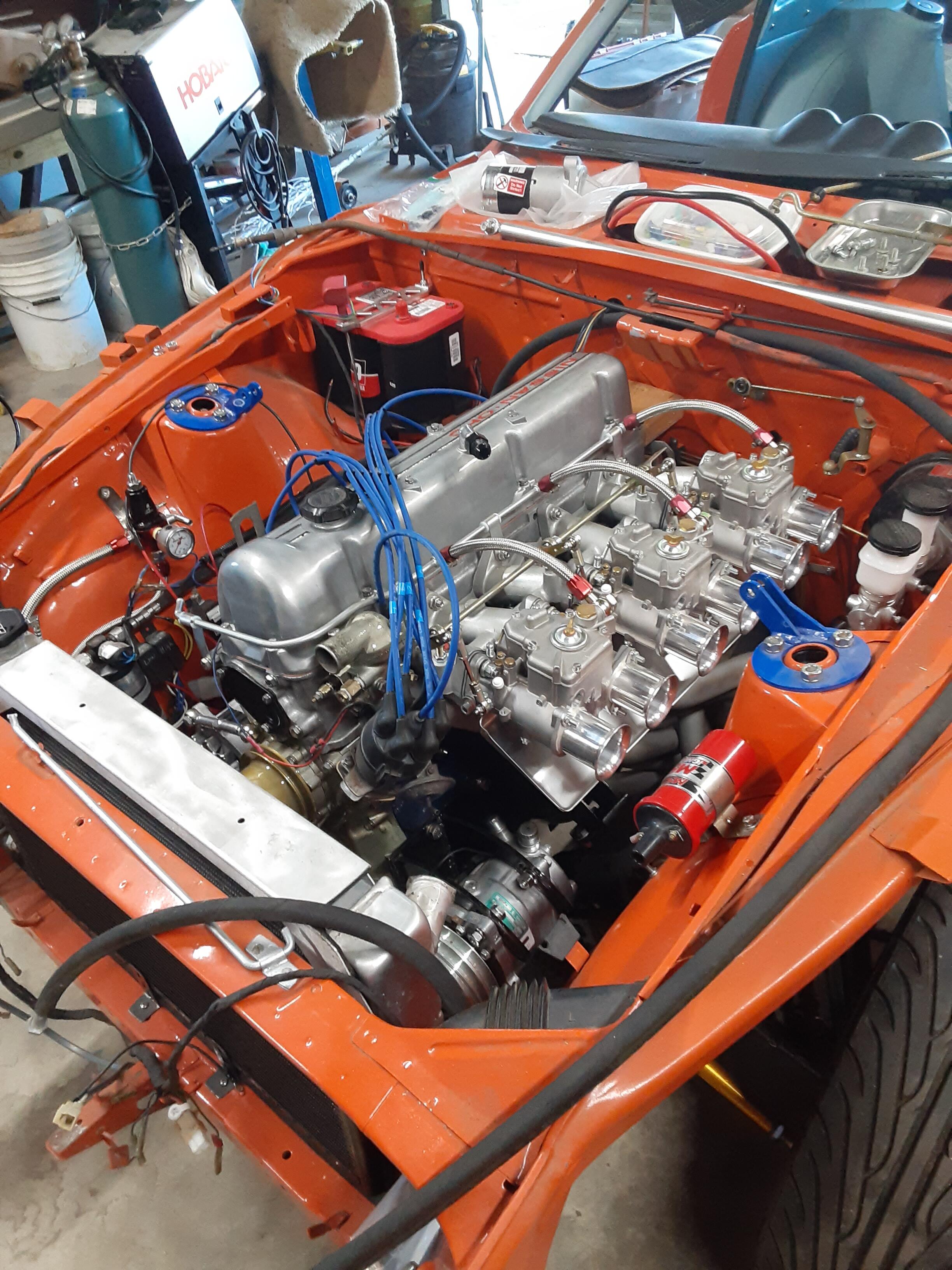
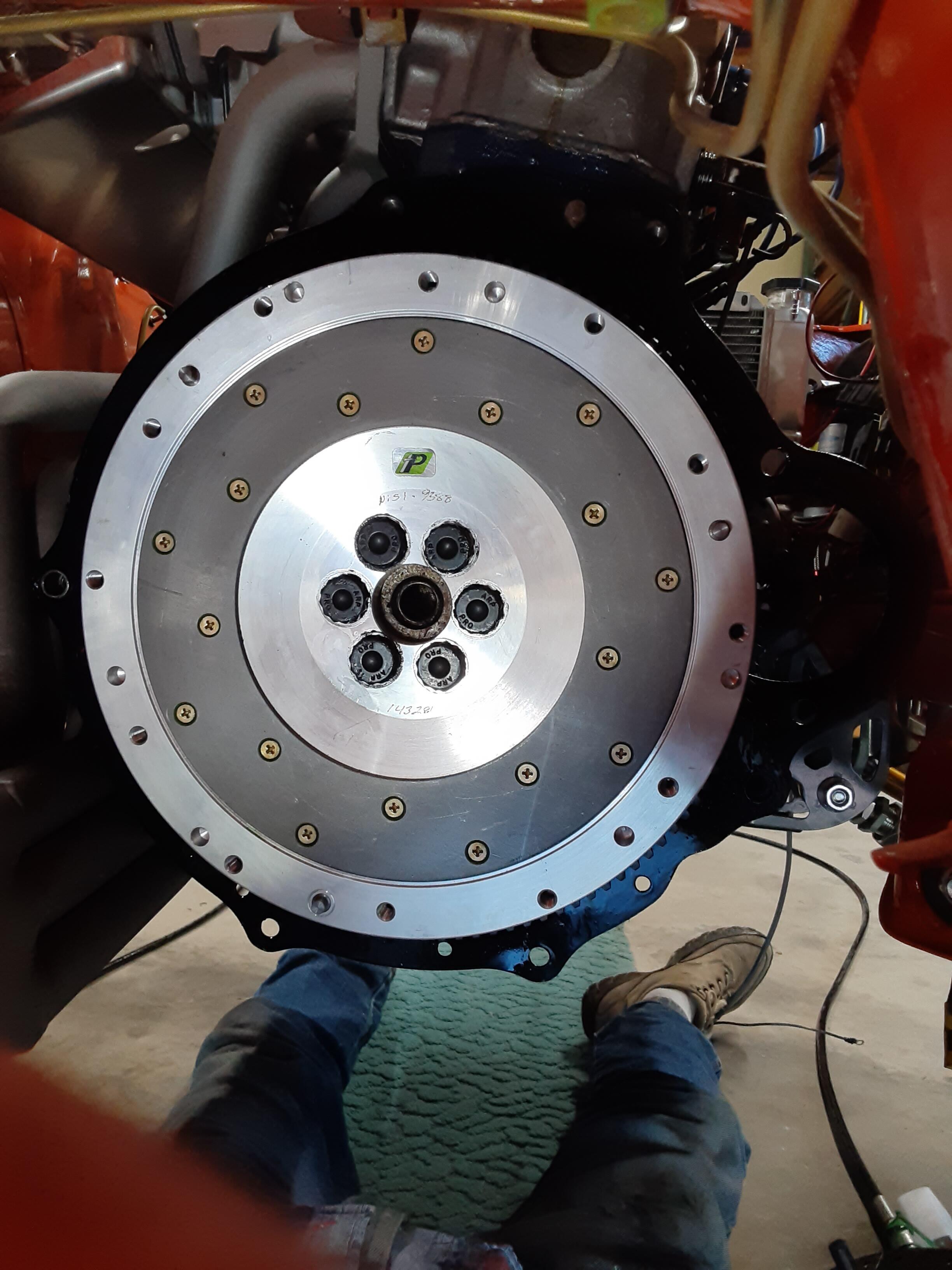
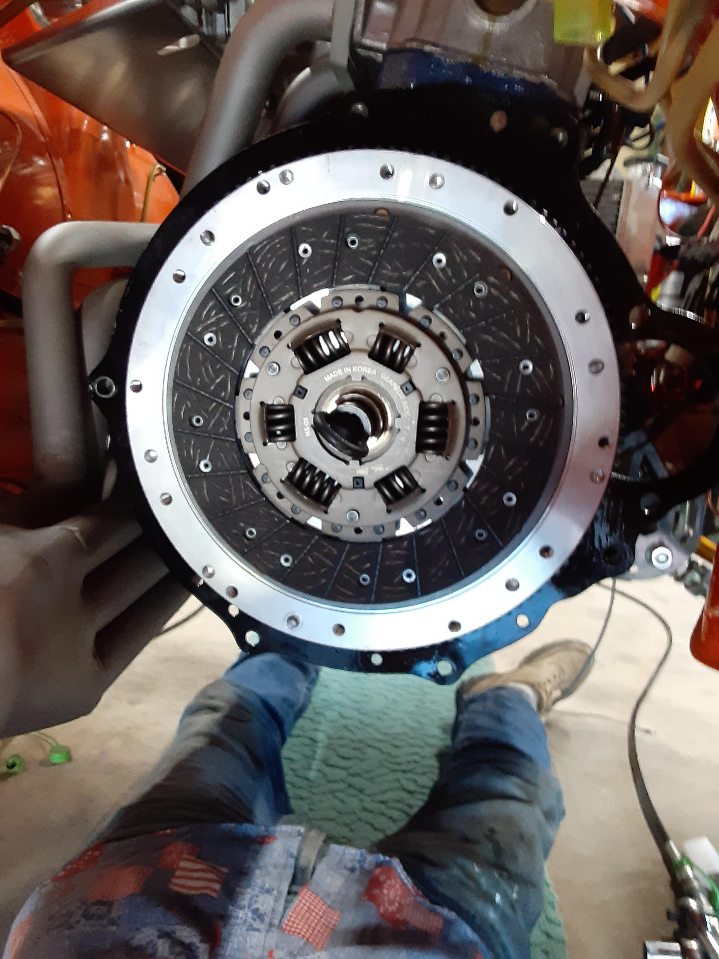
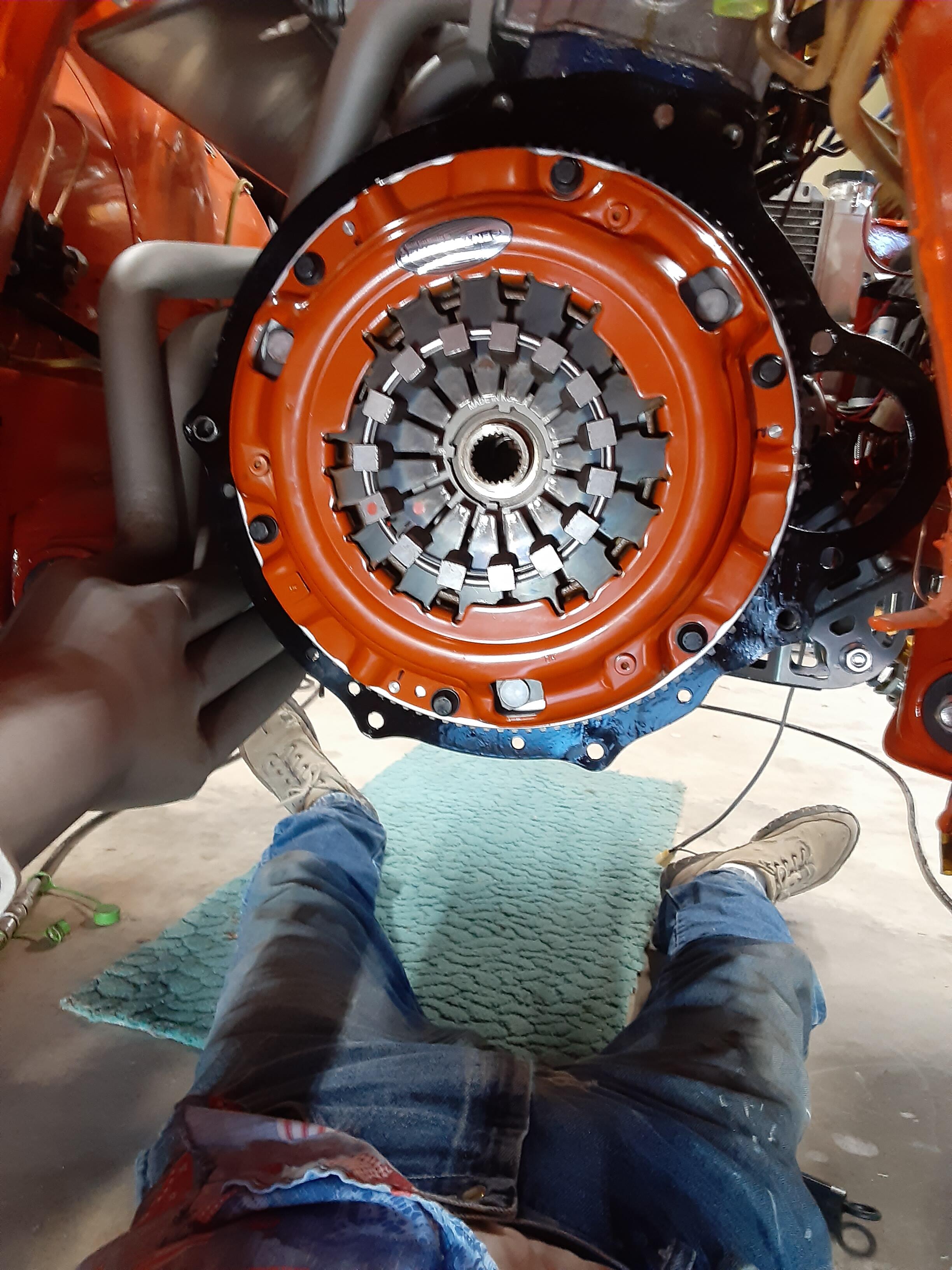
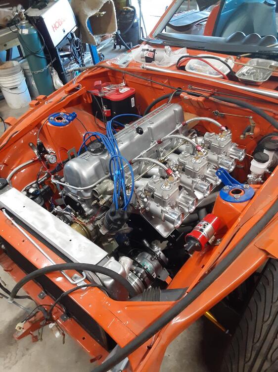
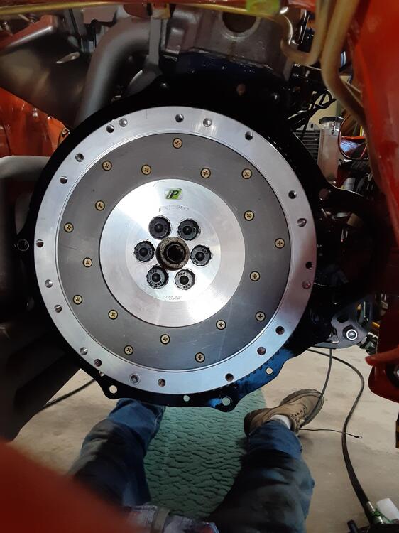
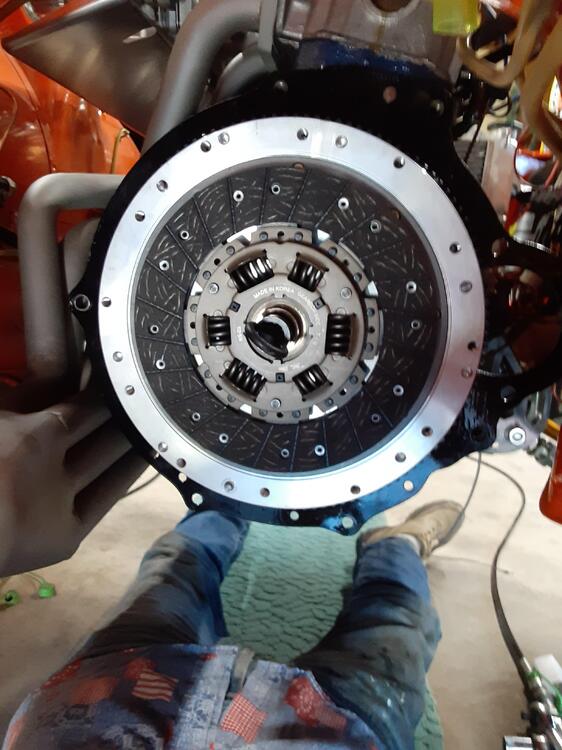
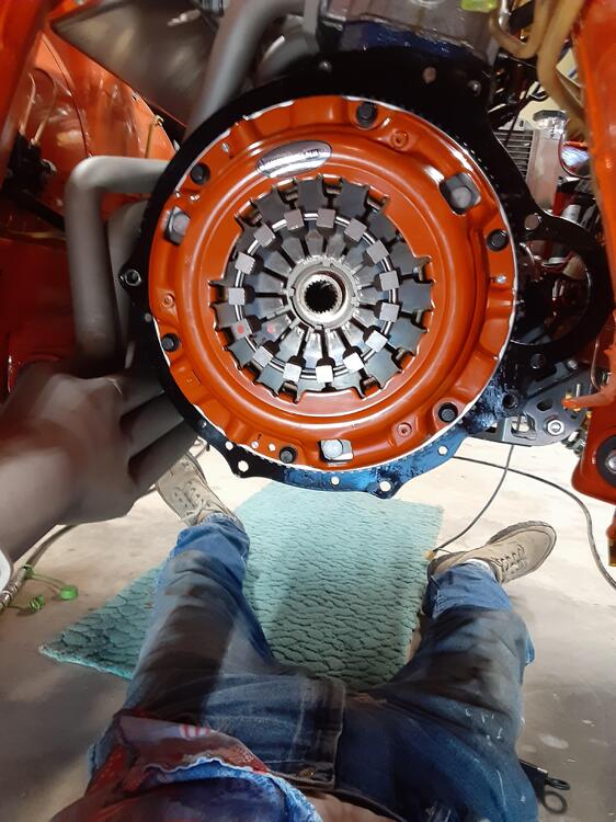
After around 15 years of restomod work, I finally got an engine back into my car. It's a 3.1 L stroker. Oh, that looks so good to me. Next, I added the Findanza flywheel, clutch disc and Centerforce II pressure plate. Woohoo!! Feeling omnipotent, I tried putting in the 5-speed tranny and discovered that there is not enough clearance between the 6-into-1 header and the tranny tunnel to allow this to happen. I'd have to remove (and then reinstall) both the exhaust and intake systems to open up the space, so I reluctantly decided to remove the engine and attach the tranny to it off the car. Because I removed the original engine and 4-speed tranny as a unit when I started this project way back when, I should, with the help of an assistant, be able to put the same size assembly back into the car. Indeed, that's what the FSM says to do. So, a bit of a setback, but it's all good, right? Unfortunately, I then discovered that one of the two M10x1.5 holes in the tranny bell housing where the starter motor attaches is stripped. So now I'm cooling my heels waiting on a threaded insert kit to arrive. At least it gave me time to remember that I needed to put oil in the tranny: Redline MT-90. Better to do that off the car than have a Doh! moment and have to crawl under it to complete that task. Now to blast and refresh the drive shaft.
 3 points
 -
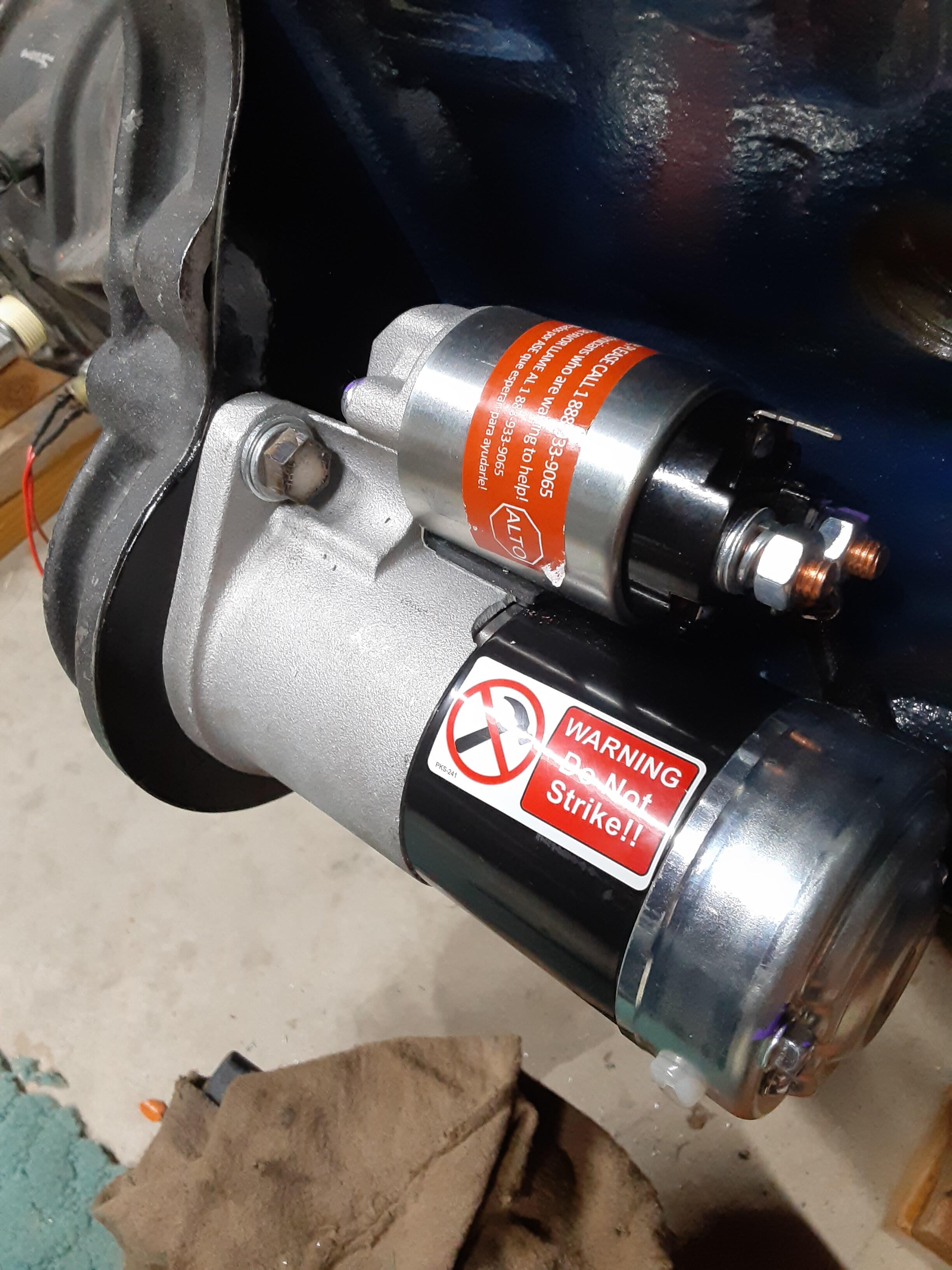
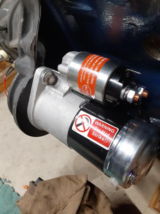
Love the "Do Not Strike" sticker. That was the only way I was able to get the old Ford starters to engage back in high school. We called it a technical tap.2 points
-
2 pointsI'm not convinced that you have an ignition problem. First, you said that the spark at the points is weak and intermittent. My reaction that it "Good. Your condenser is working." In other words, you don't WANT a spark at the points because any spark there will eat up your points. The whole reason for the condenser is to suppress the spark on the low voltage (the points side) of the coil in order to extend points longevity. Don't consider a weak spark there a problem. Consider it a benefit. Second, you say you're getting 8.5 Ohms between the open points and ground. I do not necessarily believe that is a problem either. What you could be measuring is the load to ground of all the other things that are tied to that same B/W wire elsewhere in the car. Such as..... Your fuel gauge, your water temp and oil gauge, the tach, your choke light, etc. I could easily be convinced that all that stuff in parallel works out to your 8.5 Ohms. So... Have you looked for spark at a spark plug? A nice hot spark there would be desirable!! If you have good spark at the plugs, then have you put a timing light on it2 points
-
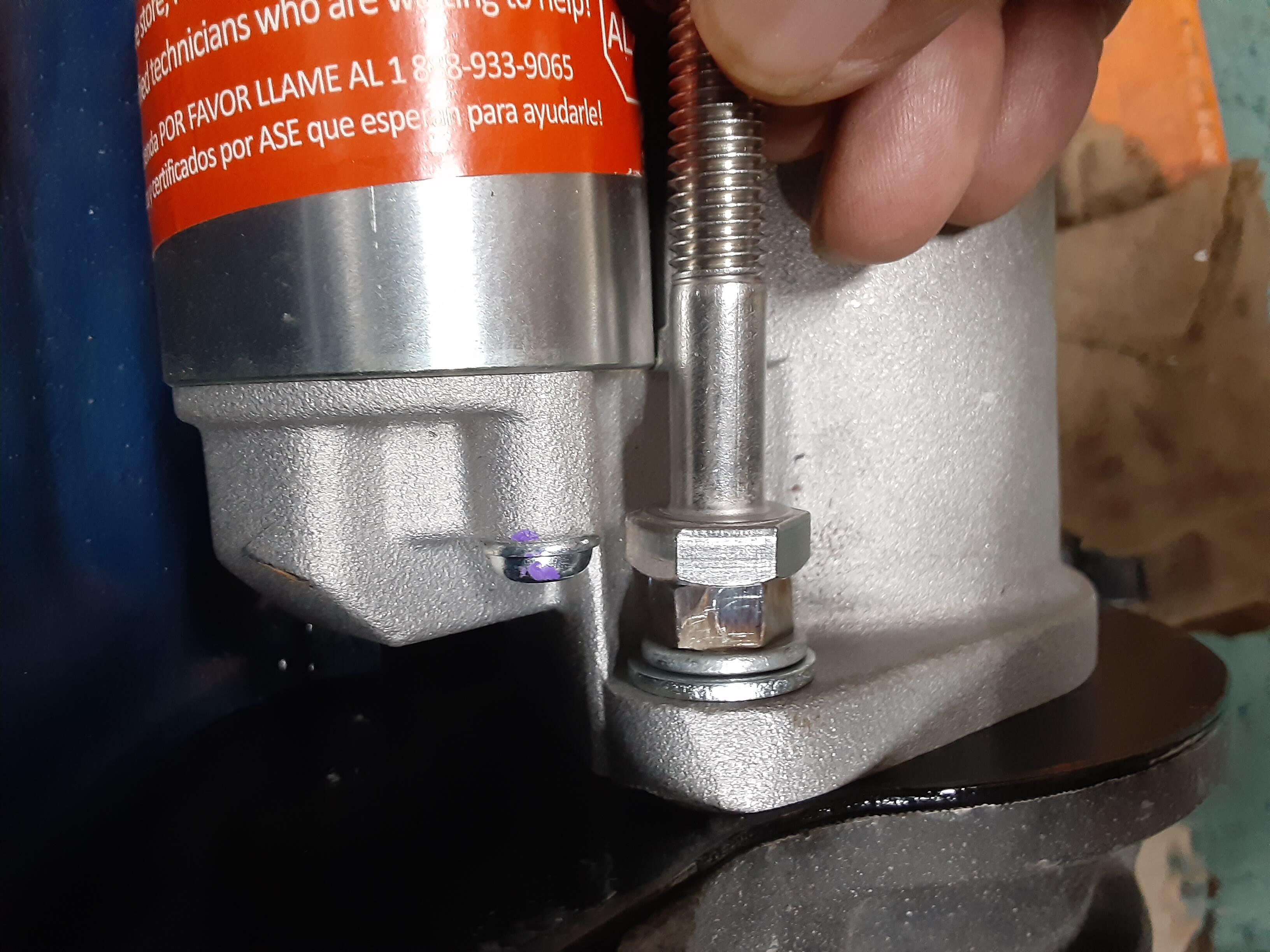
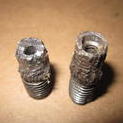
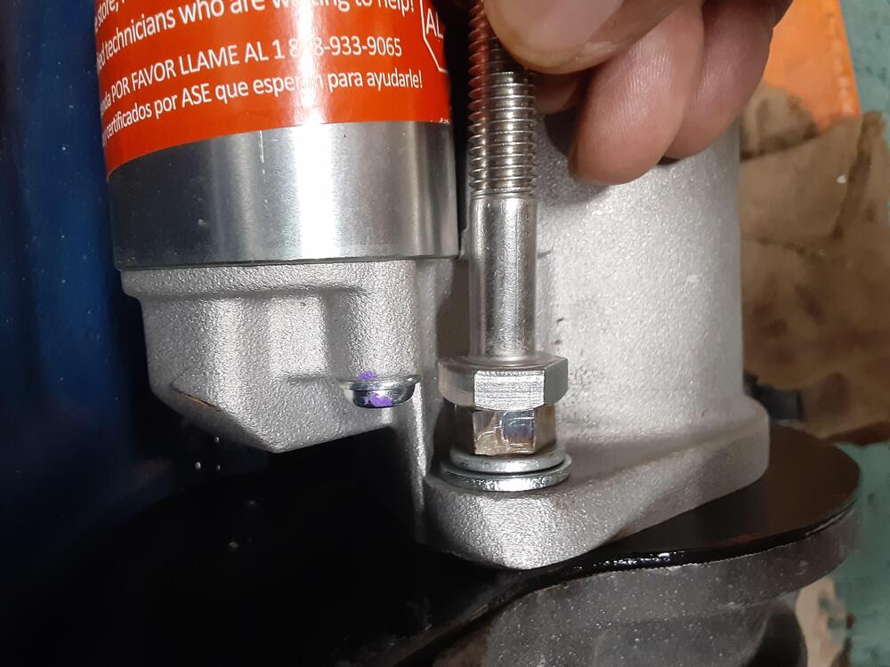
Well, that insert is now in the tranny - likely until the sun engulfs the earth in a few billion years - and the starter is now attached. The only issue was that I wanted to use stainless steel bolts to hold on the starter. The problem was that all M10x1.5 SS bolts have 17 mm heads and that size head makes it impossible to get a wrench or socket on the upper bolt (at least with the starter I'm using). So, I used my bench grinder to turn a 17 mm hex head into a 14 mm one and it works beautifully. First photo shows top "14 mm" bolt and second has a 17 mm one alongside for comparison.
 2 points
 -
I was going to comment this as well. Aside from leakage out the rear ( 🫤 ), the level/angle of the unit may result in over/under fill. My 2-cents.2 points
-
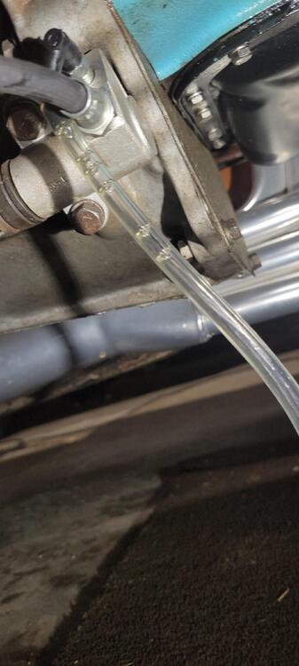
2 pointsI messed with it for a minute or two. Not done yet though. I'm going to pull all the old out and replace. $5.99 a quart for dot 3. It had air in there..
 2 points
 -
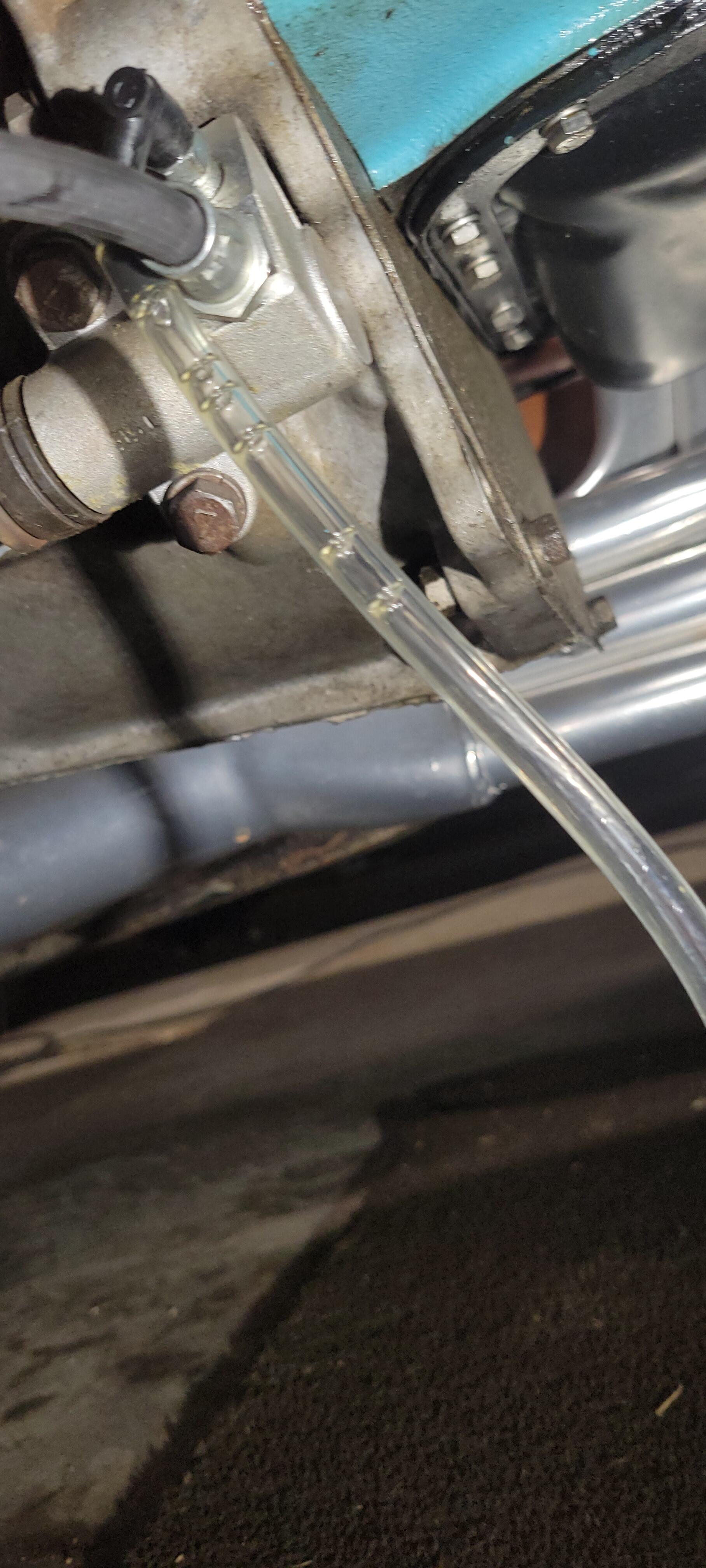
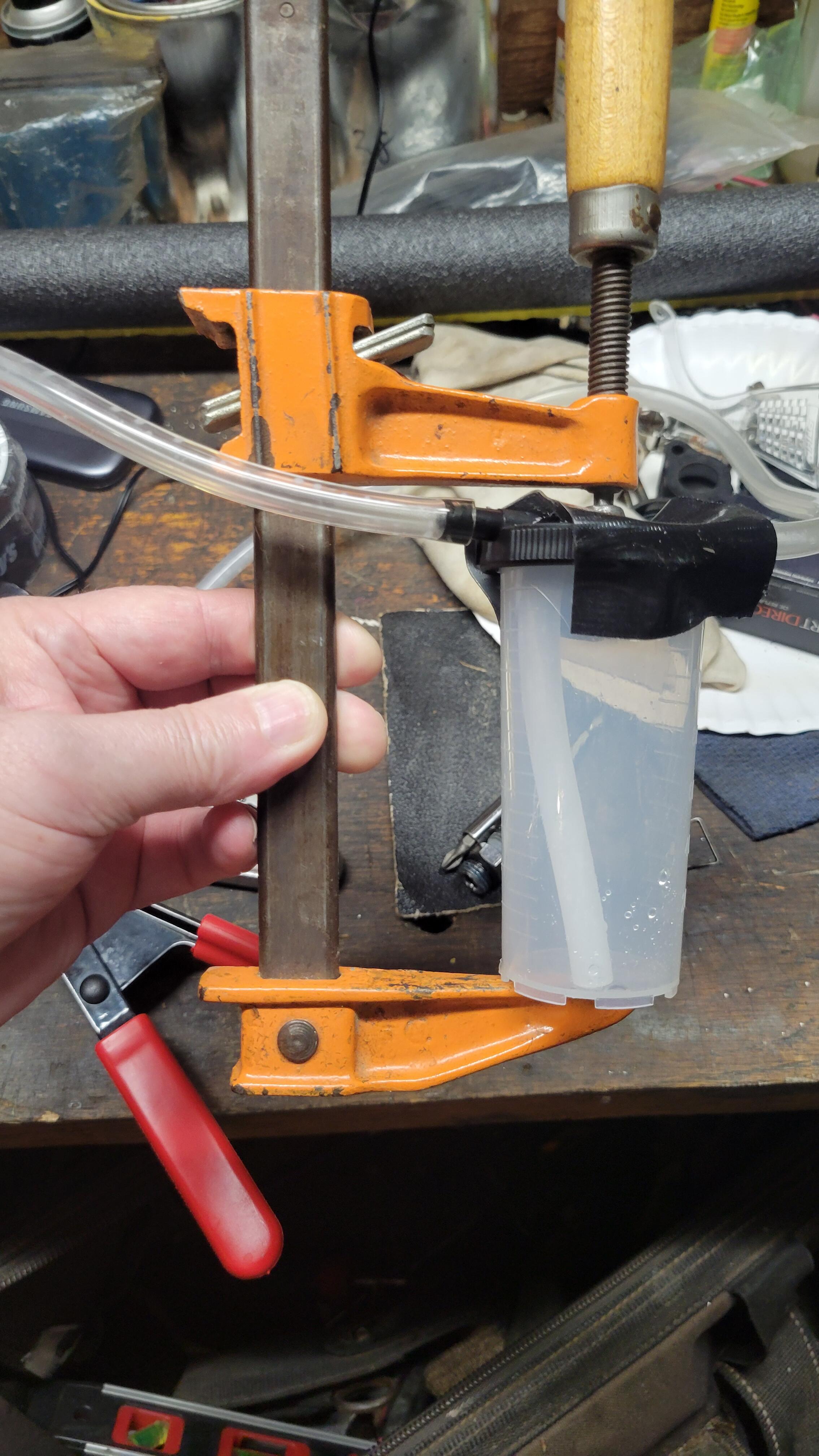
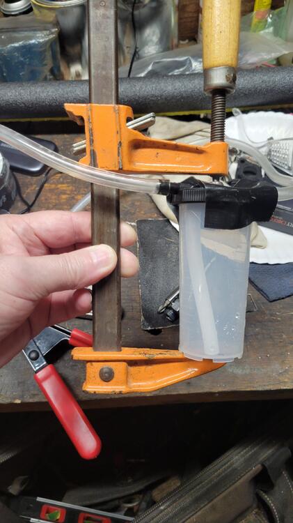
2 pointsI put those self bleeders on my 280 in 2011. Can't remember why I didn't use them on the 240 in 2015-2016? I've used a contraption I came up with when I realized the cup wasn't holding the vacuum, too small of an oring wouldn't let it seal. Messing with brake fluid on 54 year old paint freaked me out when I found a small drop by the inspection lid above the brake stuff. I had driped a little refilling the clutch master. Washed that whole fender down with Dawn soap and water. Staying away from the 240, I've done my beater D21 pickup with good results. My shade tree correction for the crappy oring not sealing was a wood clamp.
 2 points
 -
A reprint from 03/1997 as well. https://jdm-car-parts.com/products/3-1997-published-1970-datsun-240z-owners-manual-nos-extremely-rare?srsltid=AU7gw4UCH-sGpGn2x4fyiNpfsOjaKUdvHrCVi6Lk-BbfhUpM6NfFUz2h1 point
-
1 point
-
1 pointHLS30-029817 was a 4/71 HLS30-029996 was a 5/71 I think these were both USA cars.1 point
-
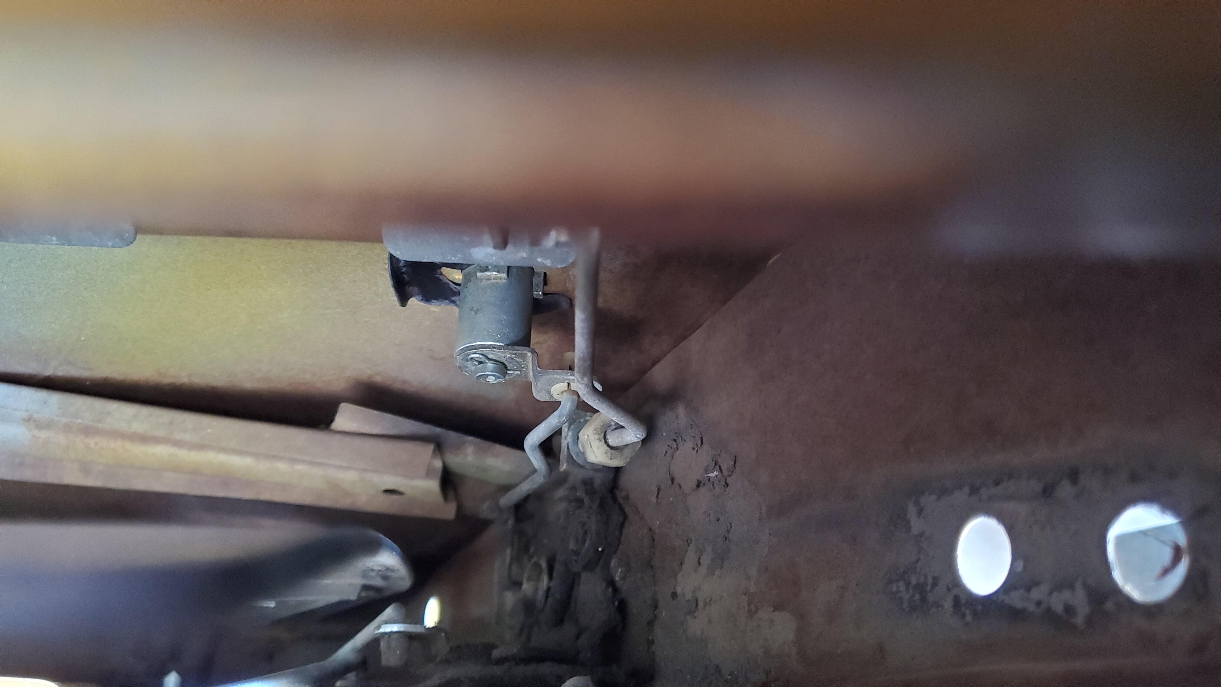
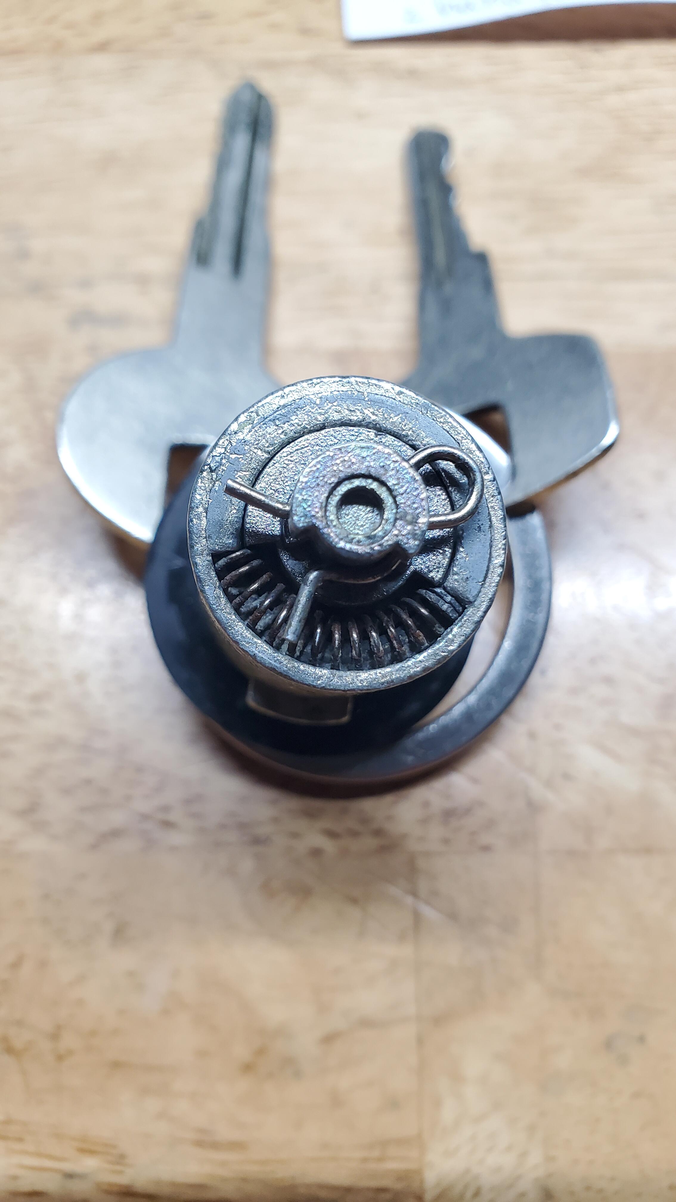
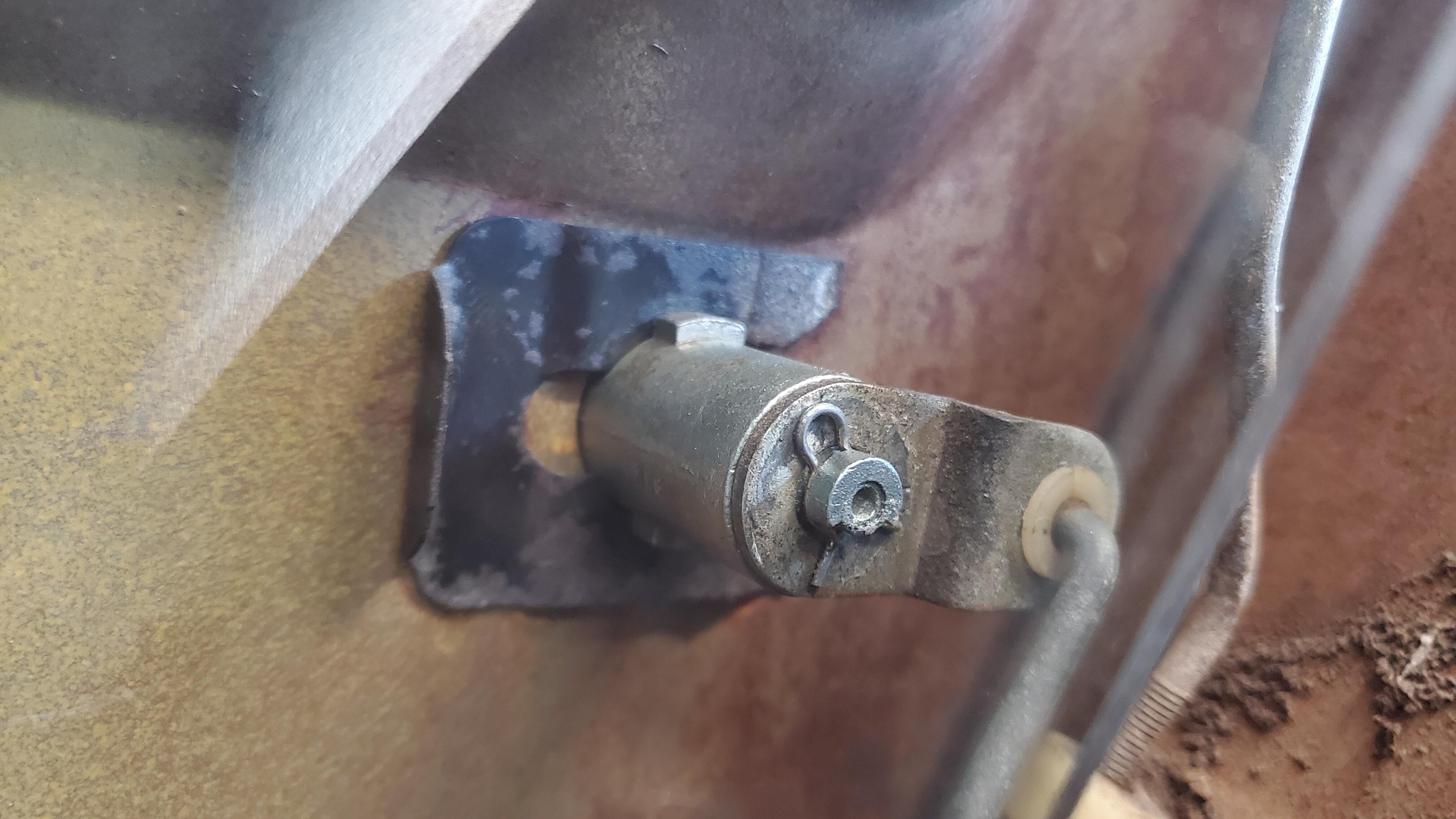
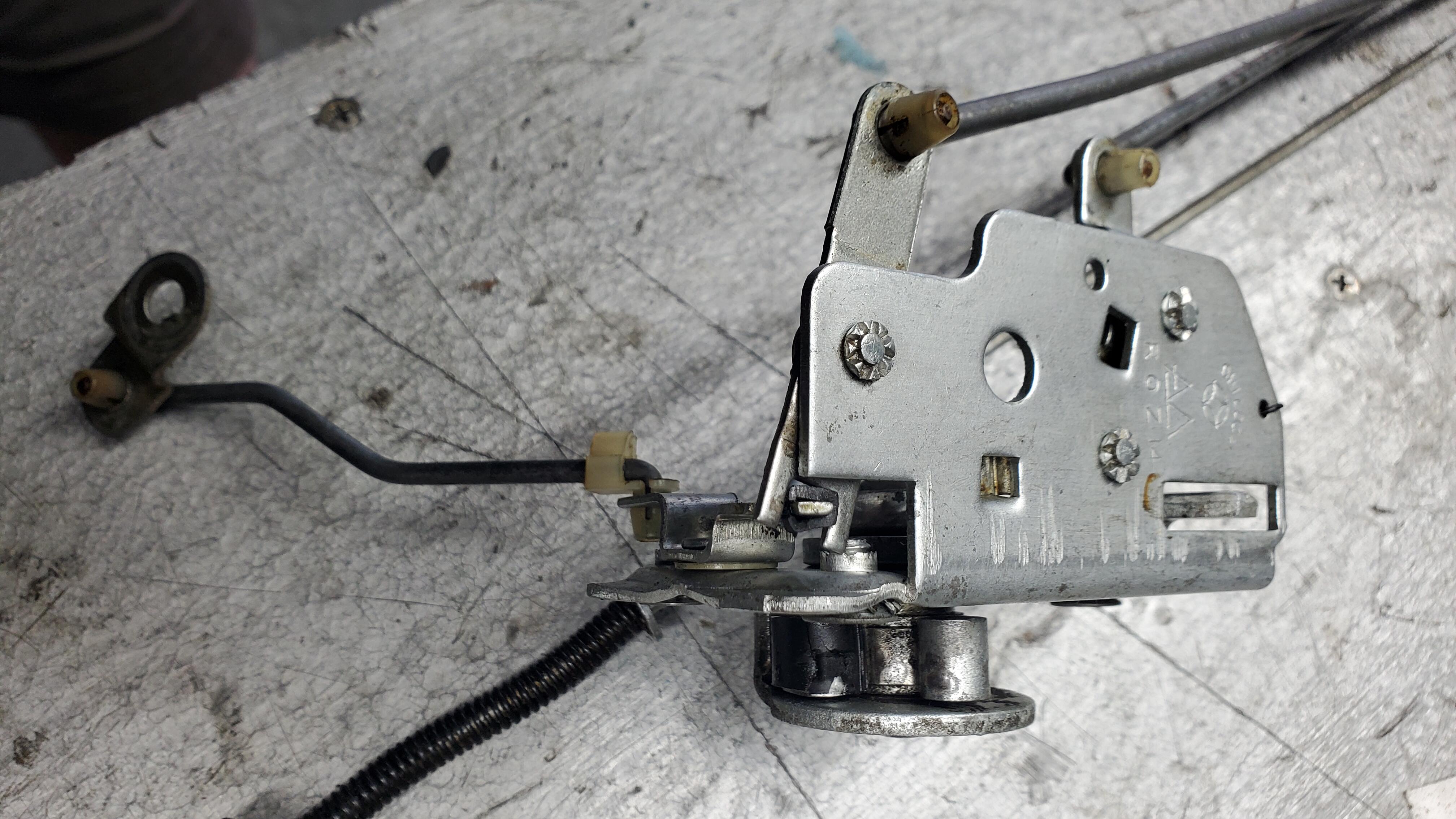
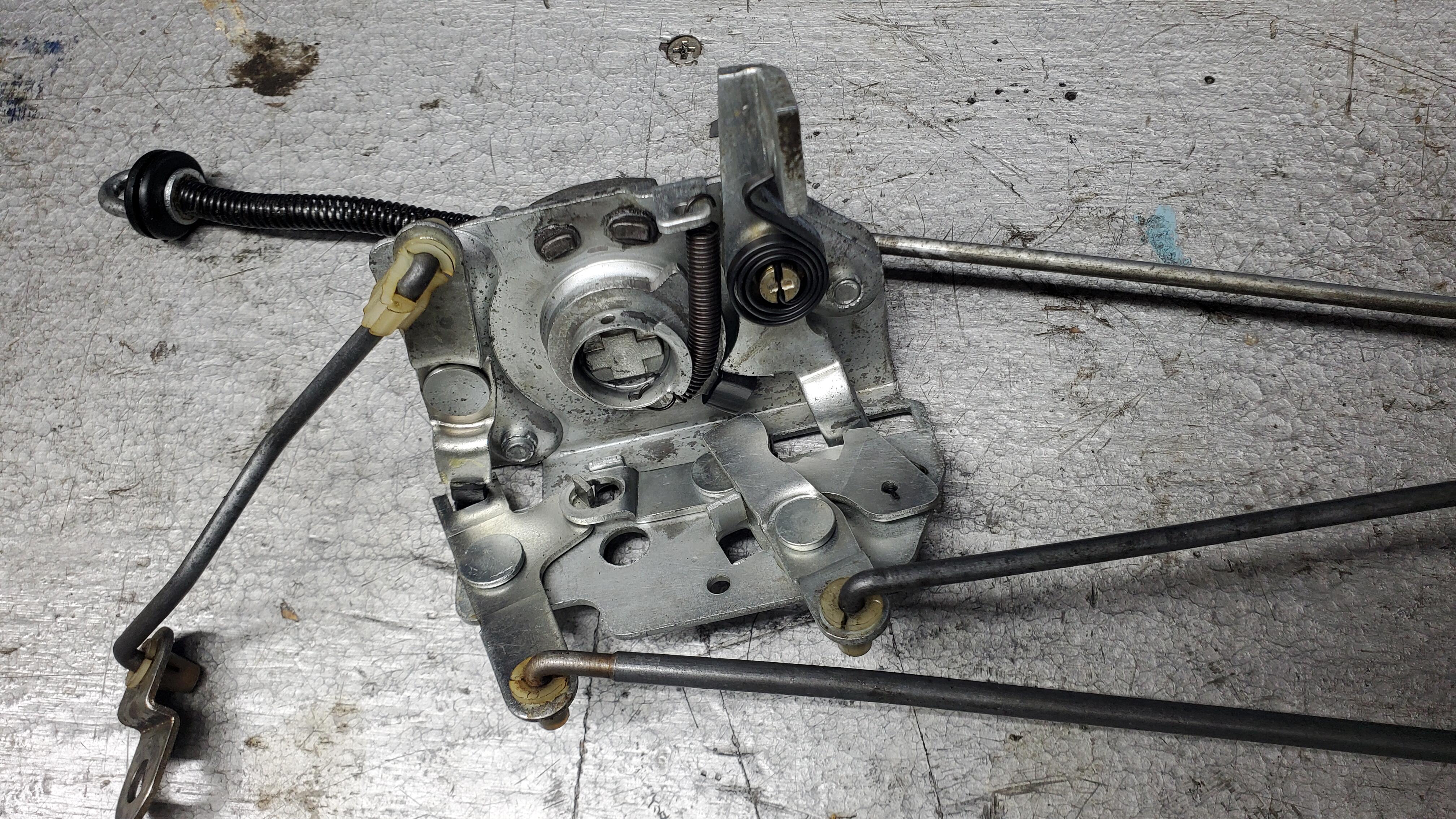
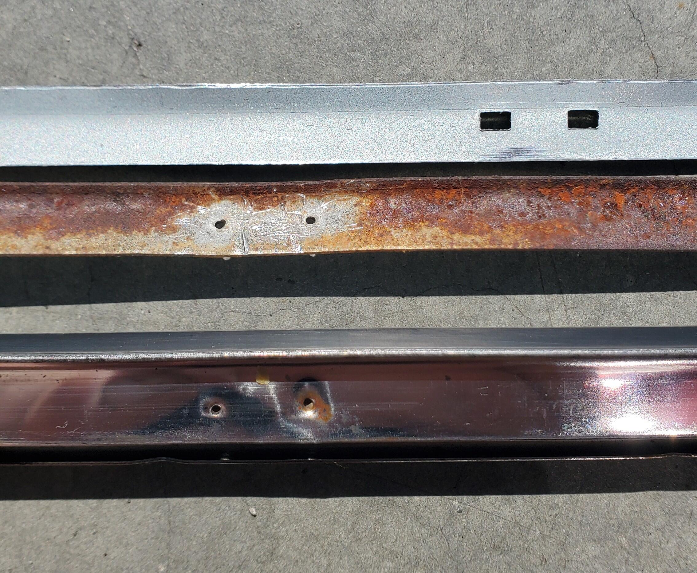
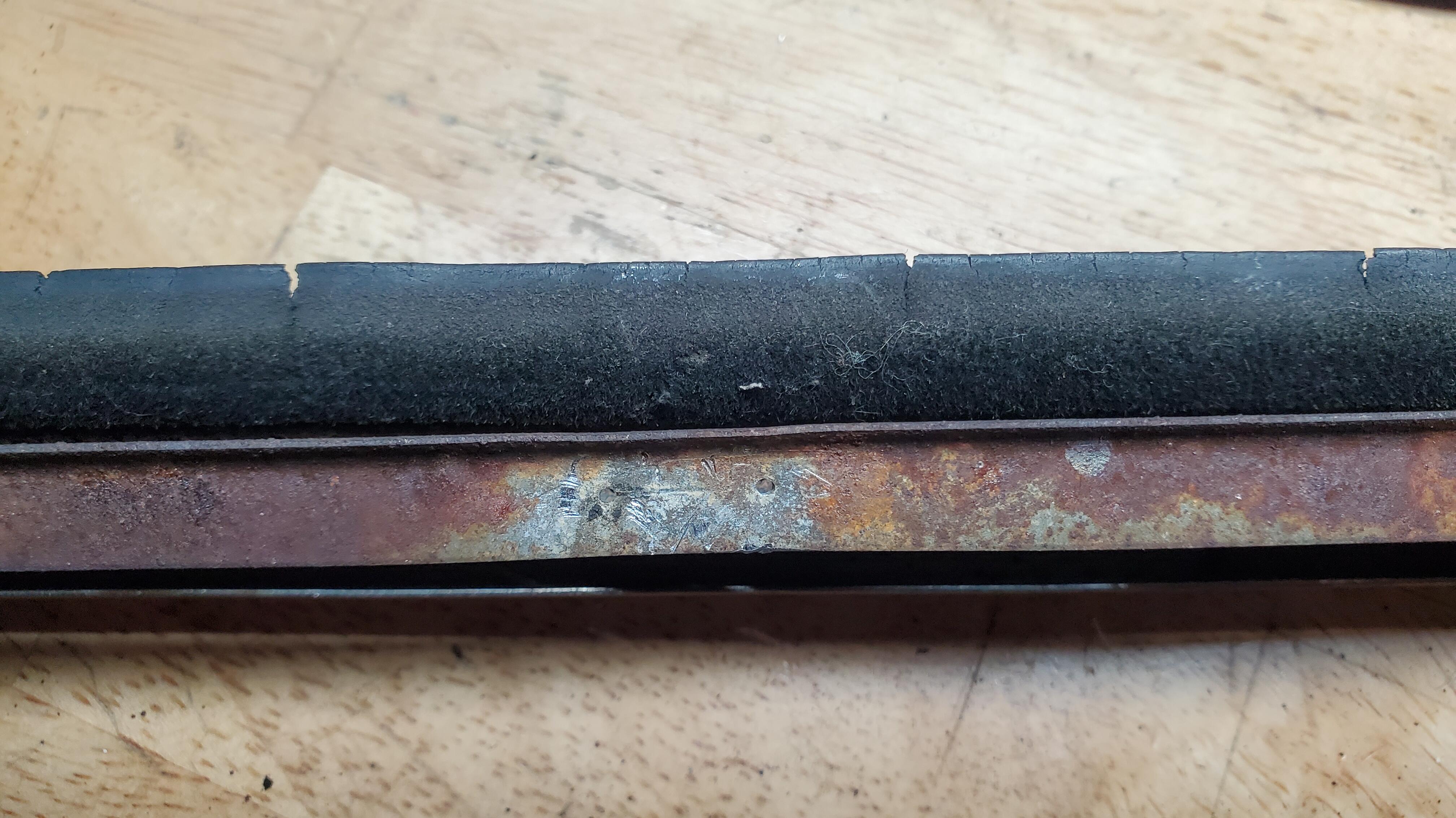
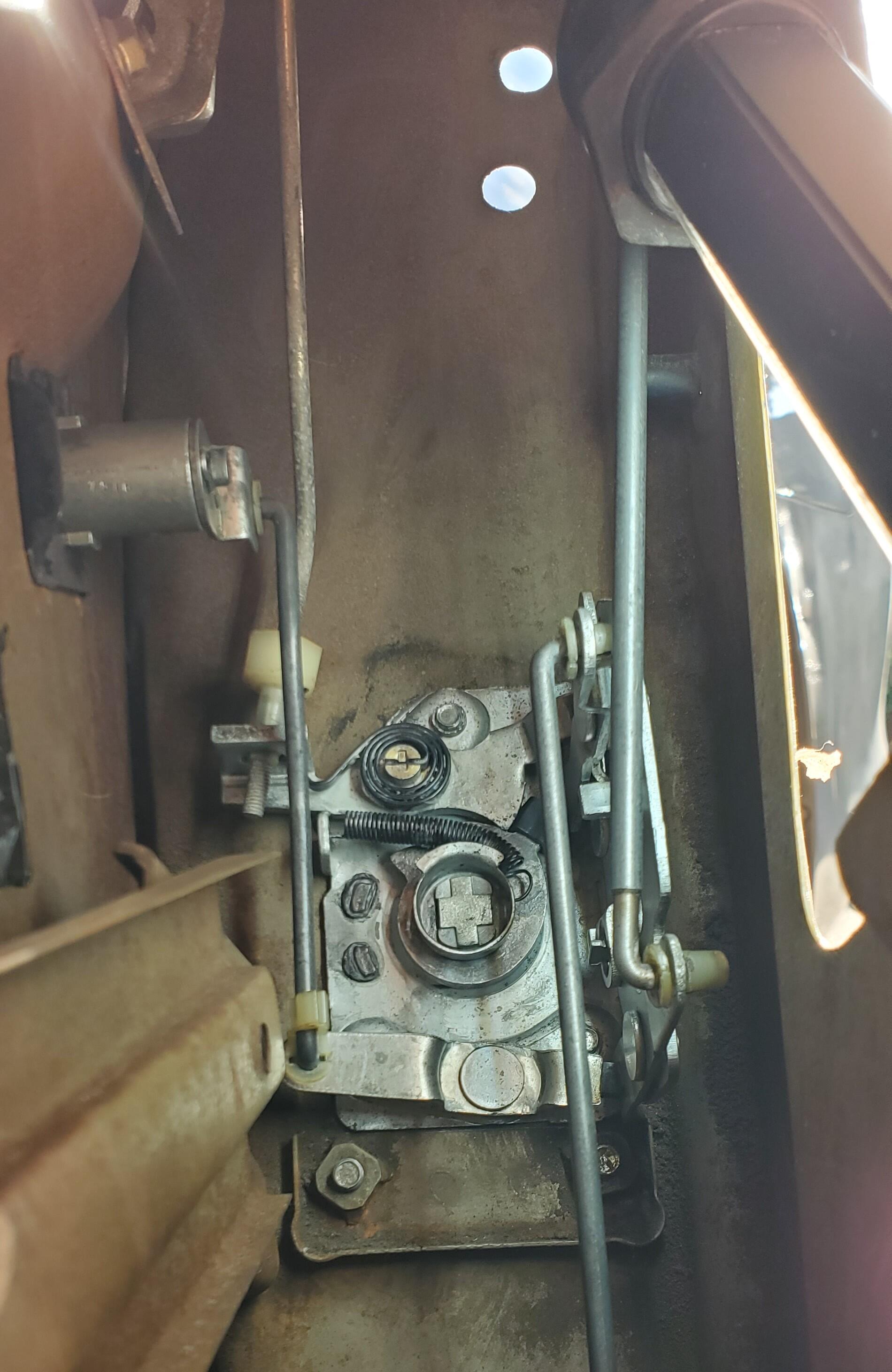
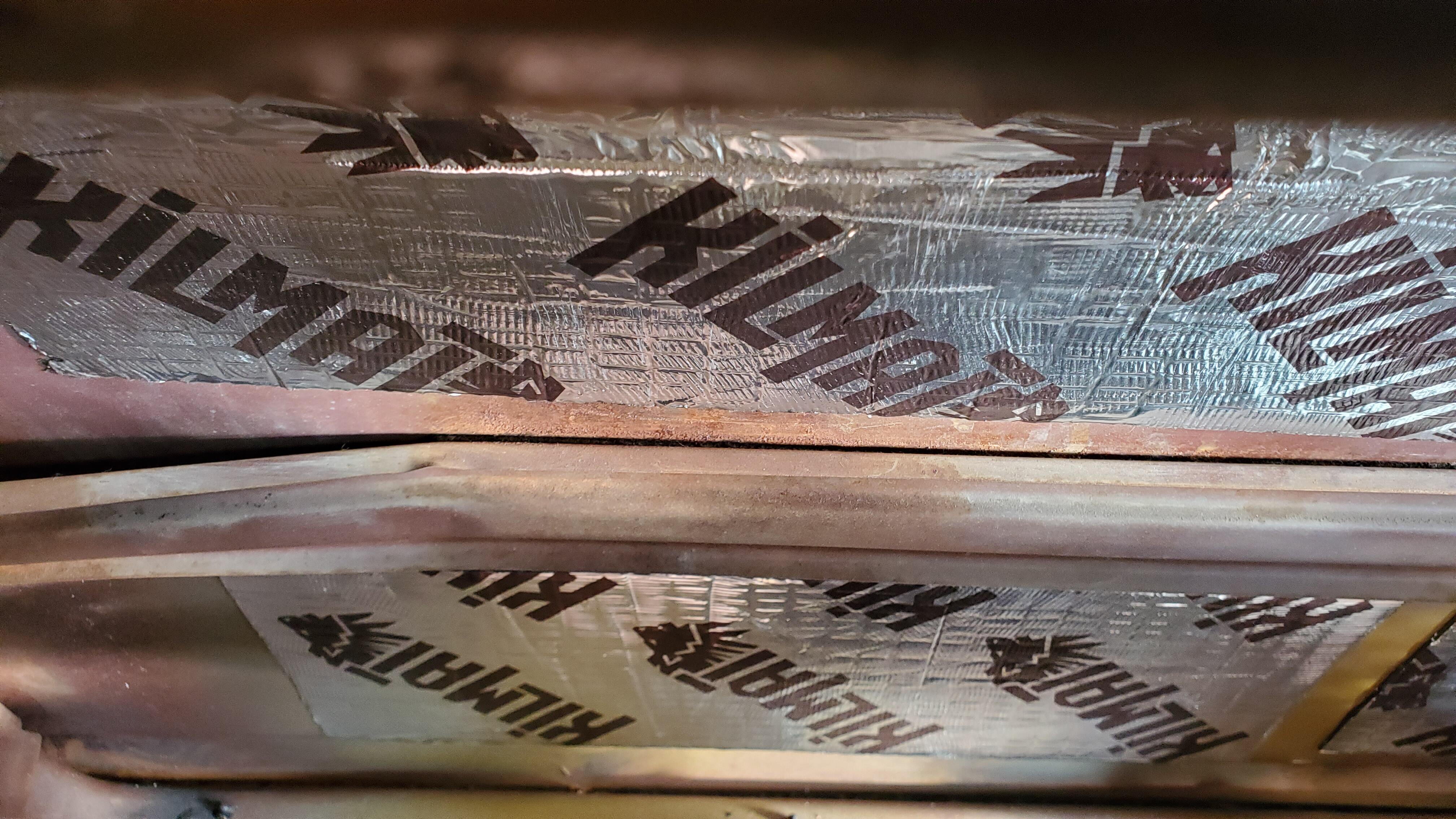
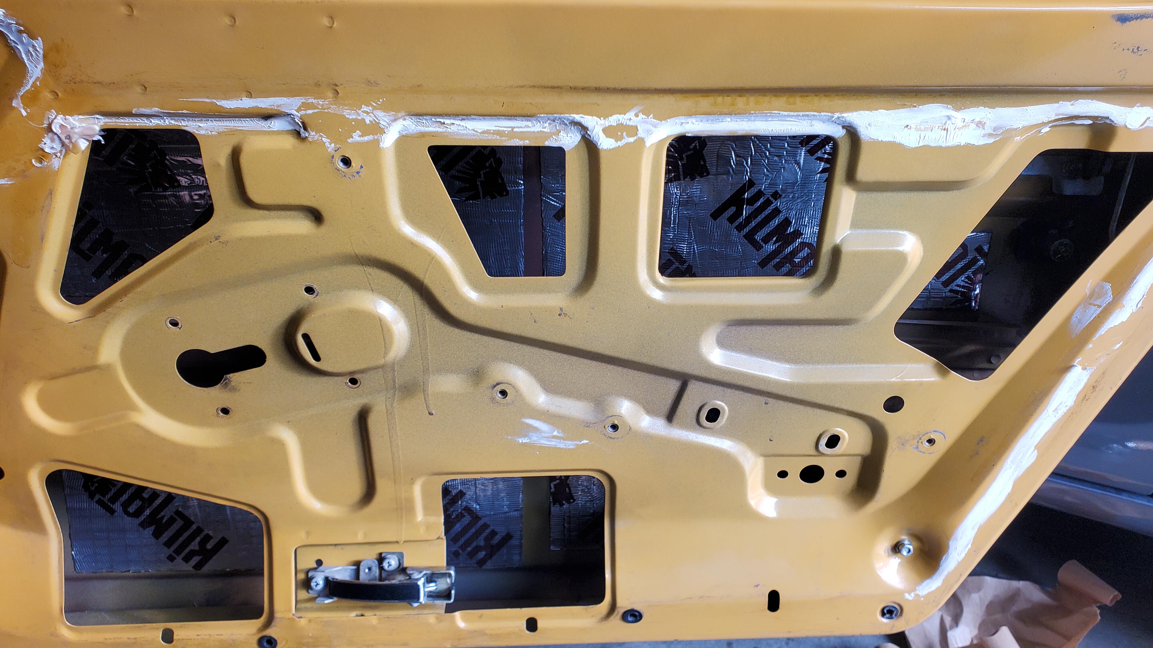
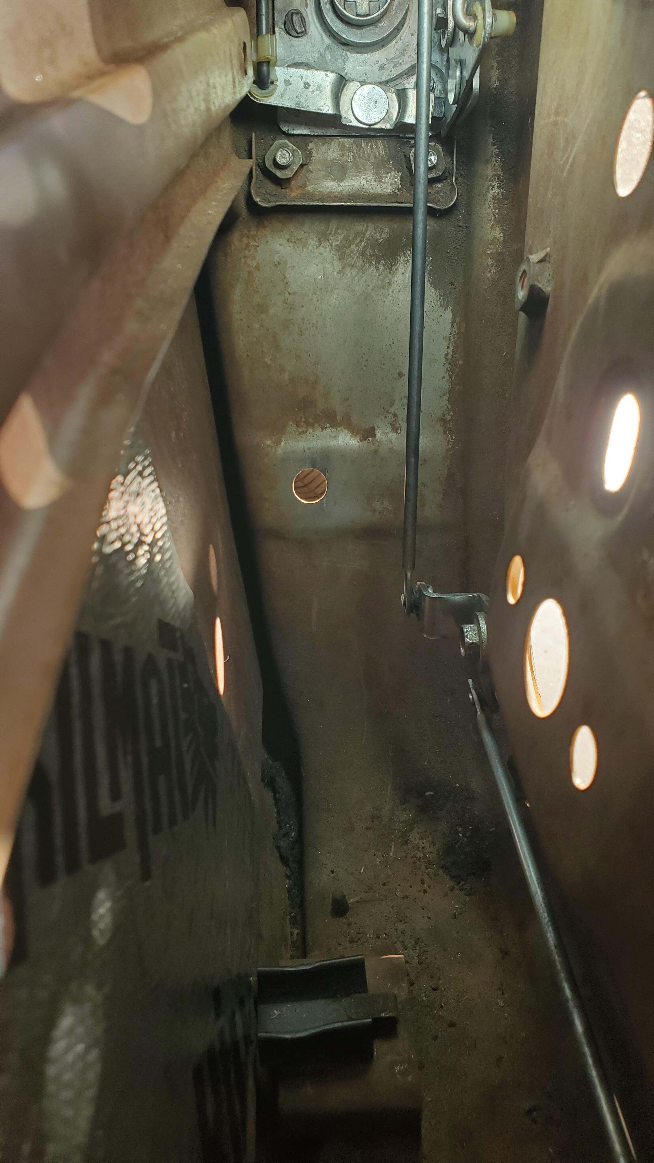
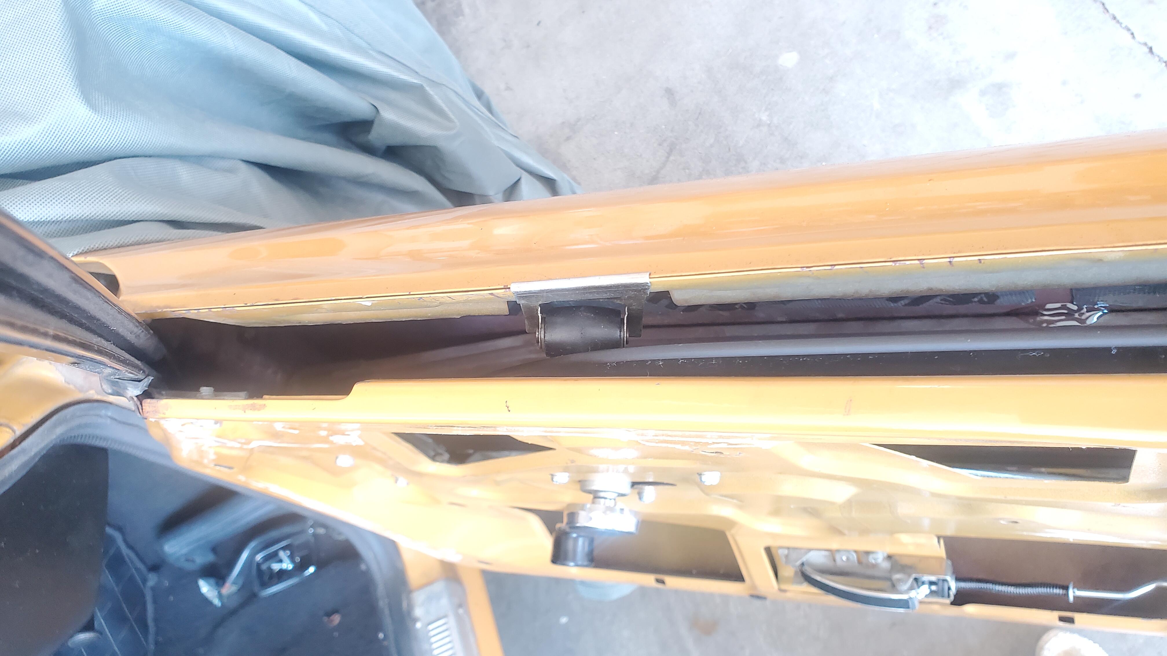
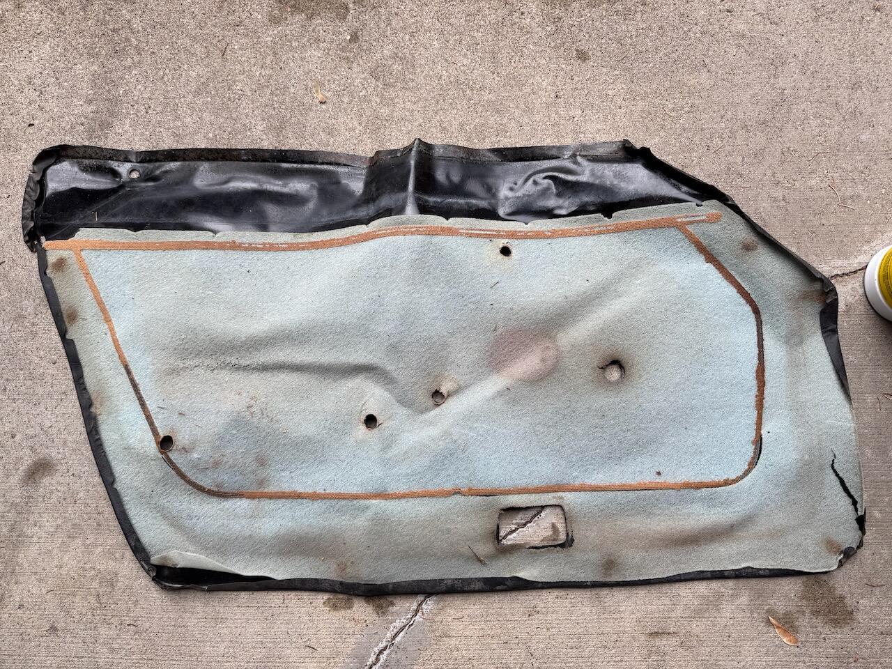
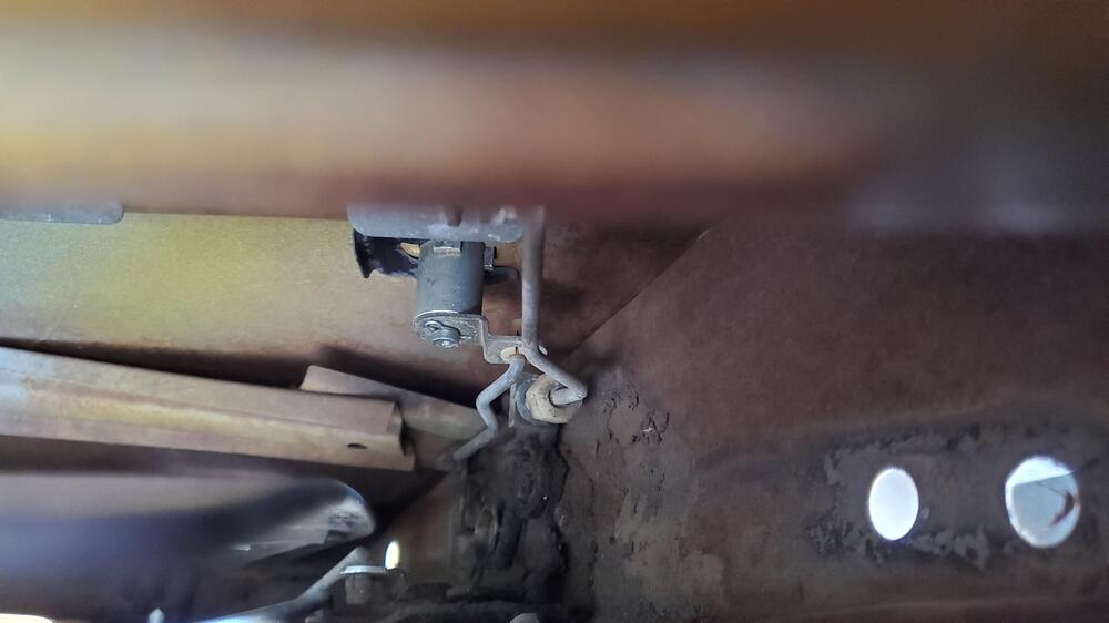
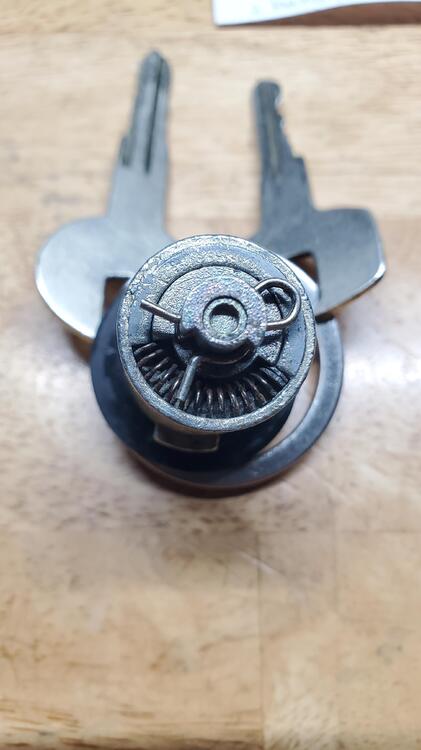
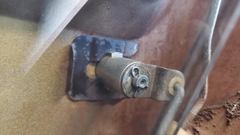
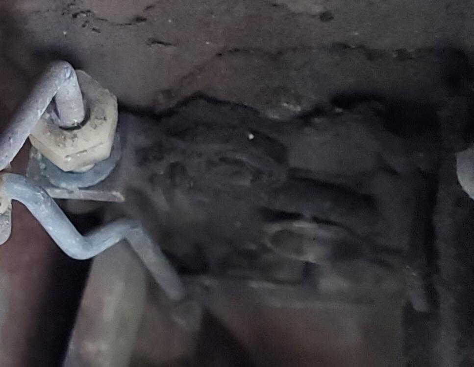
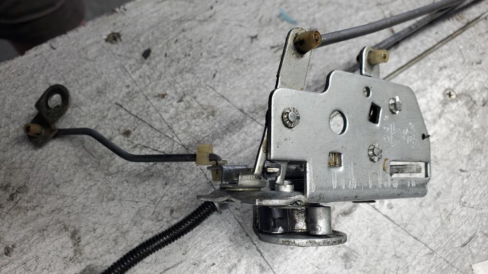
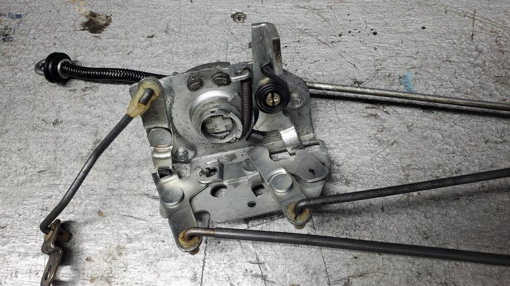
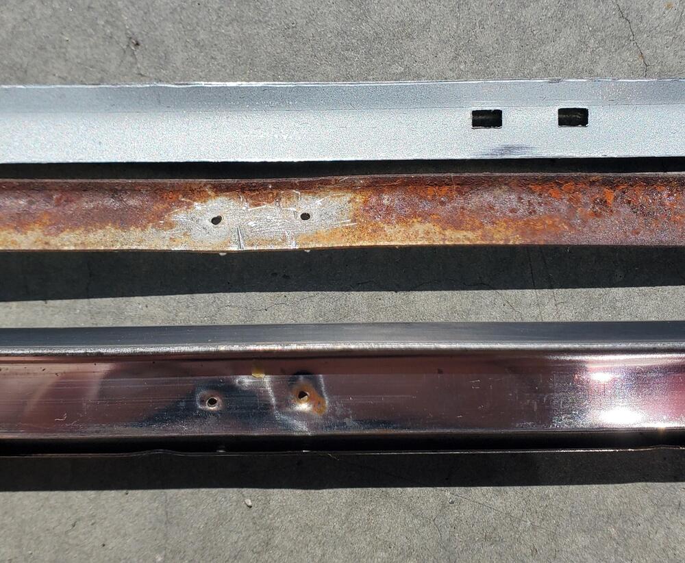
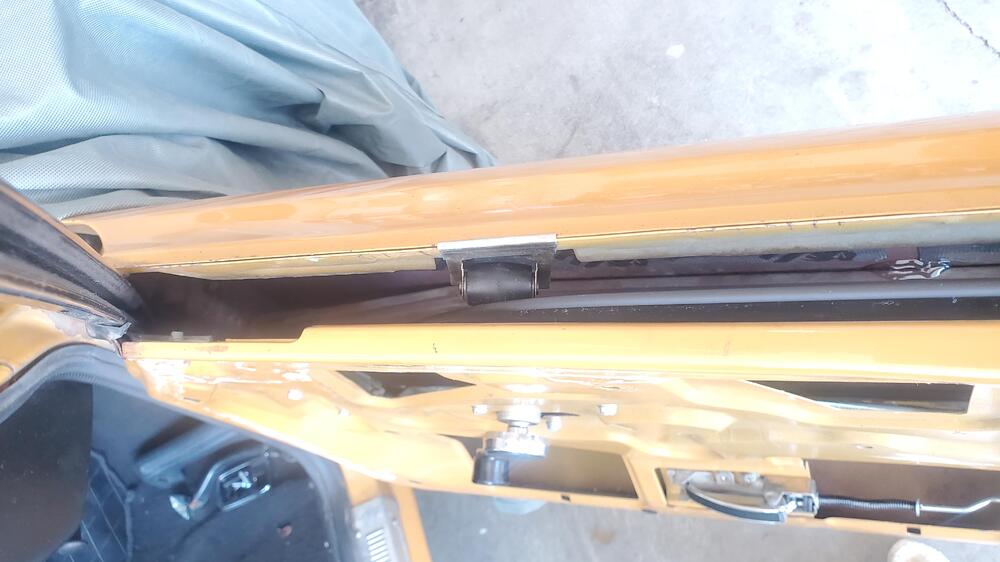
1 pointA little side project while waiting for parts from Japan (and finding a transmission window) was to repair the passenger side lock cylinder. It just won't work with the key. I decided to take it apart. First, to get it out. There is a very small pin on the back holding the push rod mechanism on. Release that pin, (hold onto it tight as it will drop into the bowels of the door) and slide off the lever. Once that is off a quick pull on the clip and the lock is out. Some thorough cleaning and a dry lube saw it working right as rain. But, I did notice the lock hinge was quite filthy. well, take it out and clean it as well. A quick removal and cleaning had it working perfectly as well. Getting this far meant I had to take the door card off and that revealed a completely hardened outer rubber belt and an inner felt belt that was non-existent. I ordered a new inner felt from MSA and it will be here in Aug, Sept, Oct? Pending on that. I did get the outer strip and it is produced by Precision. None of the holes lined up with my original but that was not a problem. some new holes and it fits nicely. This all meant I had to remove the glass and regulator. Well, it turns out that the little plastic dust covers on the regulator pulley wheels were done. I wondered what they were when I noticed them sitting in the bottom of the door. Thankfully, user scottan from Thingiverse uploaded a file so I could 3d print some out of TPA. A wee little stretch and perfect. I also noticed that the door skin had come free from the internal "reinforcement" beam. I re-adhered it and that went a long way in reducing the buzzy vibration. The big step to reducing that was some 8mil Killmat panels. Now that did the trick. Still waiting on that felt....... Cheers
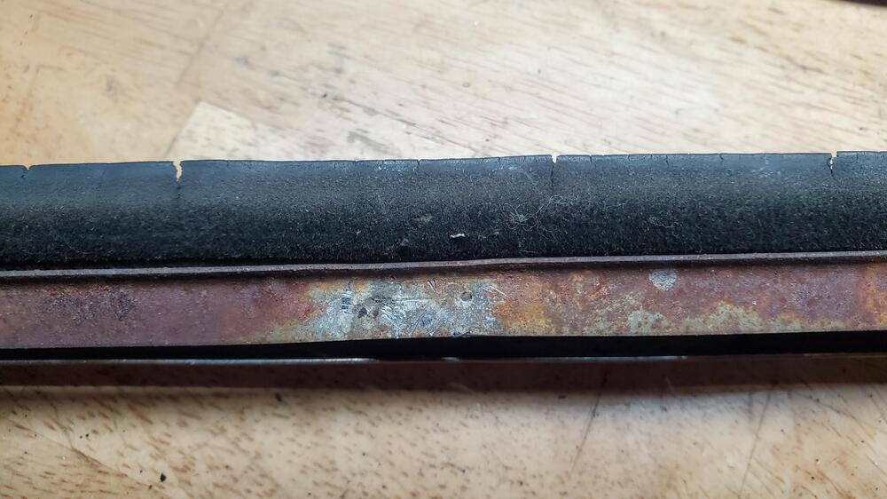
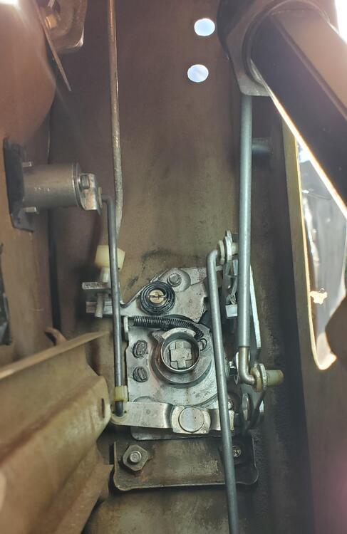
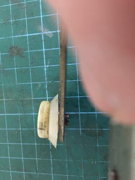
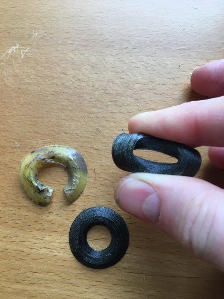
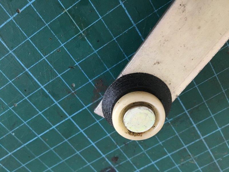
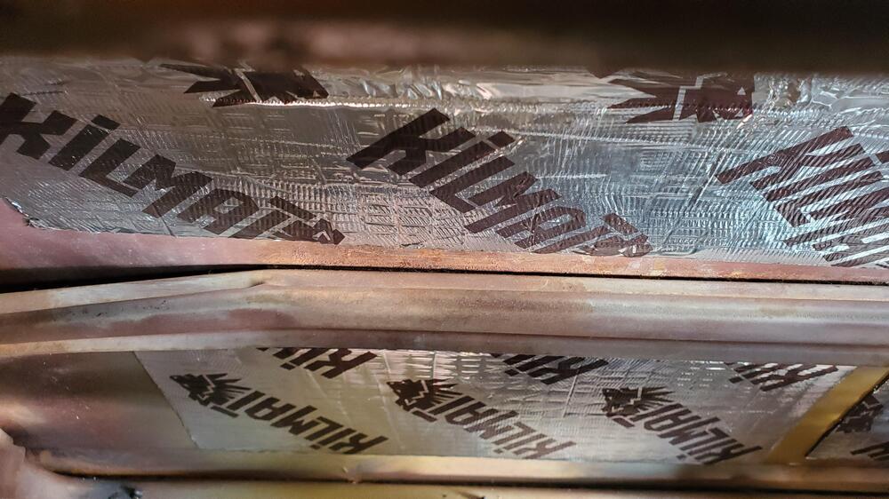
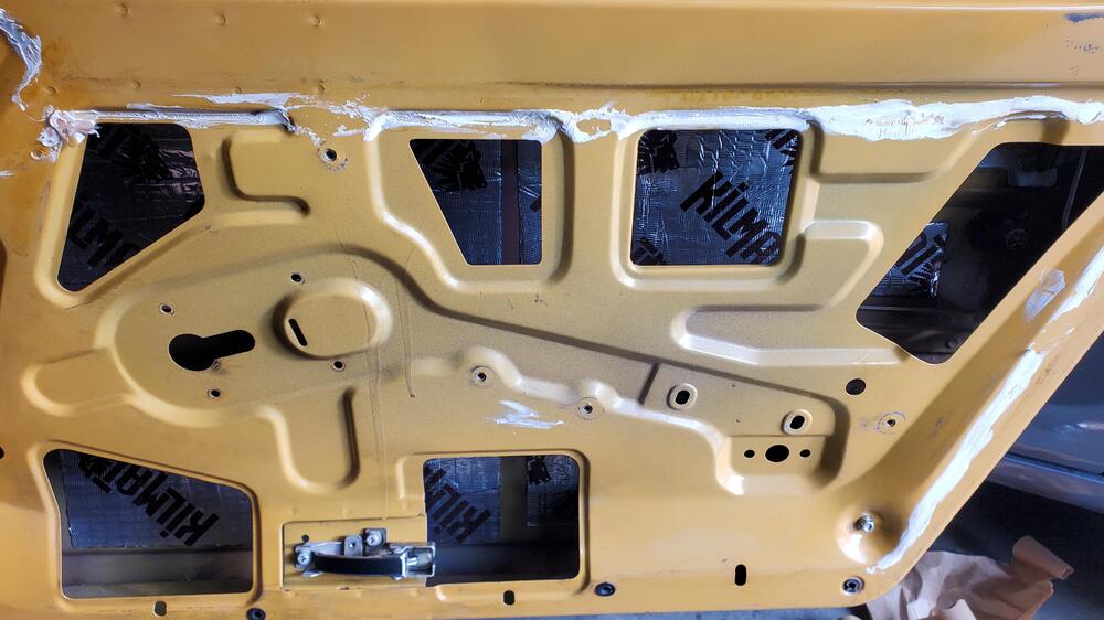
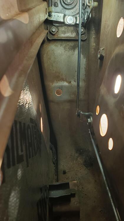
 1 point
 -
It's been a while since I've messed with one of those idle mixture screws and don't remember how many turns it takes in order to take it all the way out, but I believe there is an O-ring seal around the head. (Either there's an O-ring on it, or maybe I made one and put an O-ring on it? Don't remember.) But, in any event... I wouldn't want that screw to be run out more than maybe five or six turns. If it takes more than that, I think you might want to look into possibilities in other areas for running rich. Without and AFR gauge I think your plan is sound assuming you aren't having to run that screw out more than five or six.1 point
-
https://www.ellsworth.com/globalassets/literature-library/manufacturer/henkel-loctite/henkel-loctite-user-guide-threadlocking.pdf You're right, permanent is probably best. Don't want the insert backing out on a starter removal. Blue for the bolts, red for the insert.1 point
-
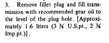
What type of insert are you using? Blue thread locker is probably enough. Red is for extreme situations. I used to run a long hose with a funnel from the engine bay down to the transmission fill hole. Just fill it to overflow. A little messy but not as messy as those screw-on pumps can be by the time you get done.
 1 point
 -
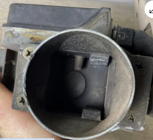
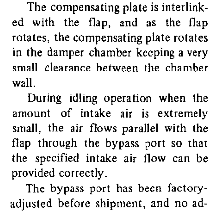
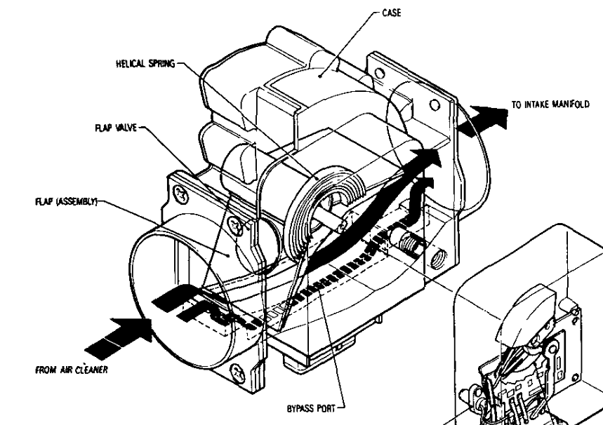
Yarb, the idle RPM control screw is on the throttle body. I don't think that the "btw" was relevant on the atlanticz page. Intake backfires will damage the AFM vane even if the passage is open. That's why Nissan put a spring-loaded relief valve in the later years of AFM. The screw controls a passage that lets air past the AFM vane so that it doesn't tell the ECU to add more fuel. I used to tune mine for emissions by backing it out until the engine starts to stumble at idle, then running it back in a half turn. In theory, once it is correctly set it never needs adjustment. That's why Nissan sealed it shut before it left the factory, in later years. But, of course, we can't help messing with things, and they left it open with only a rubber plug stopping us. Stole this picture from an eBay listing, showing the backfire valve, the round thing. Your 78 probably has one. Doesn't really matter, just interesting. Here's the extract from the 1976 FSM that kind of summarizes things.

 1 point
 -
@AndysPlit Thanks for the info👍 Yes, this is the exact article I had open while I was inspecting/cleaning my AFM. Mine looked completely factory inside, so I simply cleaned it, and sealed it back up. Yeah, no mention of the outside bypass screw "setting"... Maybe someone else will chime in with some insights on this screw.1 point
-
I think he did. https://www.homedepot.com/s/3%20inch%20rubber%20cap?NCNI-51 point
-
Hey, @siteunseen, did you get those in the plumbing department of a big box store? That's what they look like to me.1 point
-
Maybe too late but these rubber caps work good. I first used them when I pressure washed my 5 speed.1 point
-
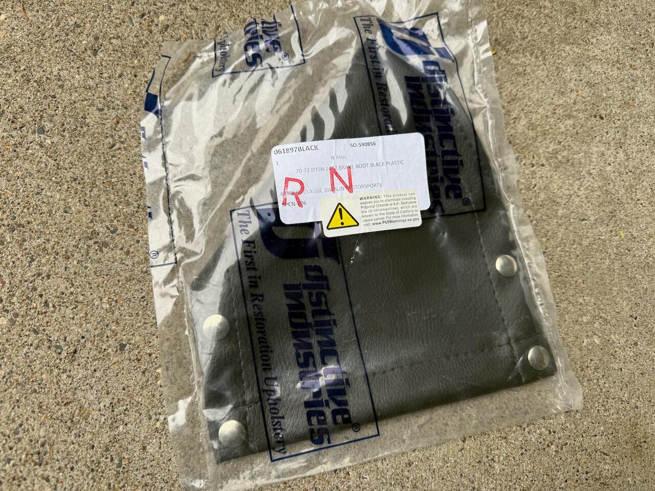
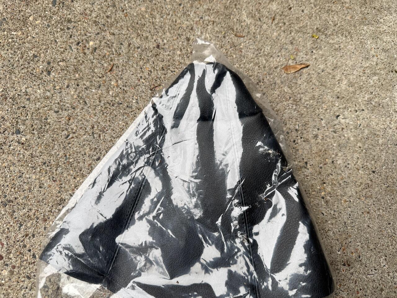
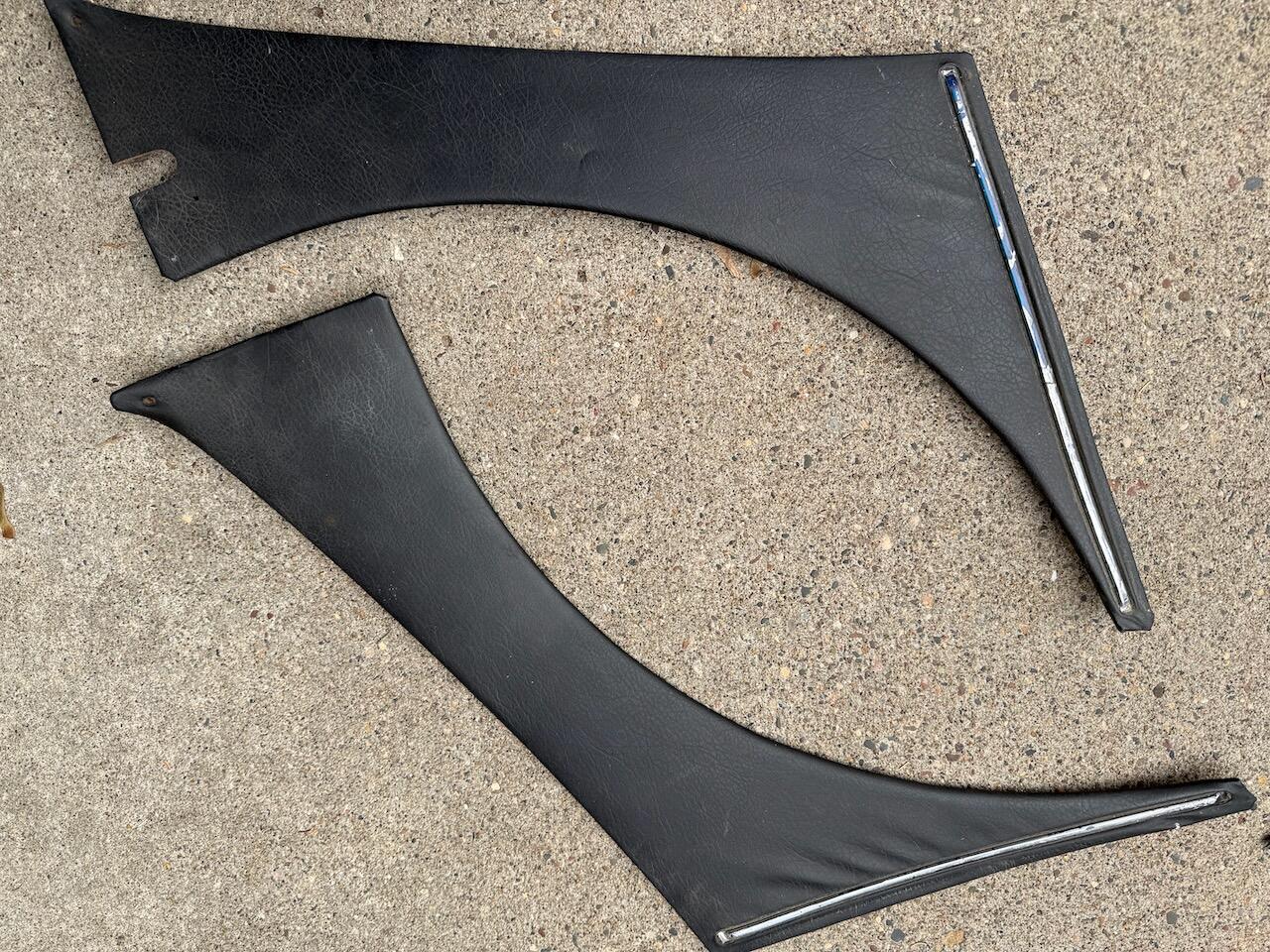
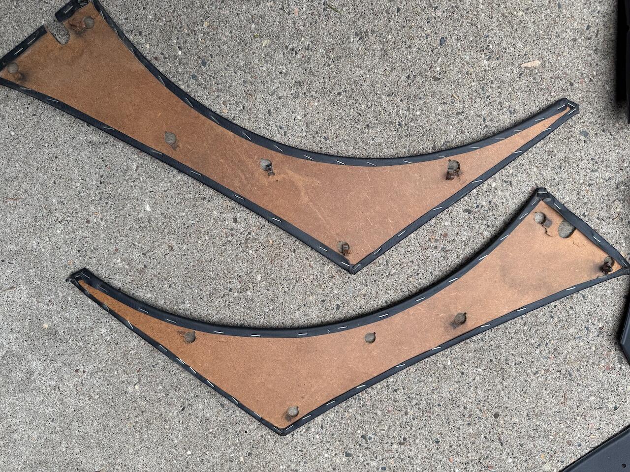
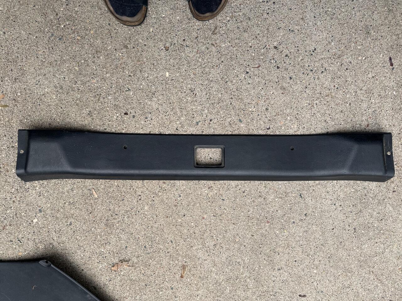
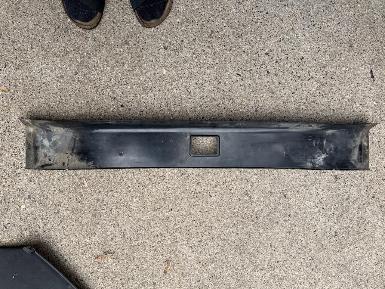
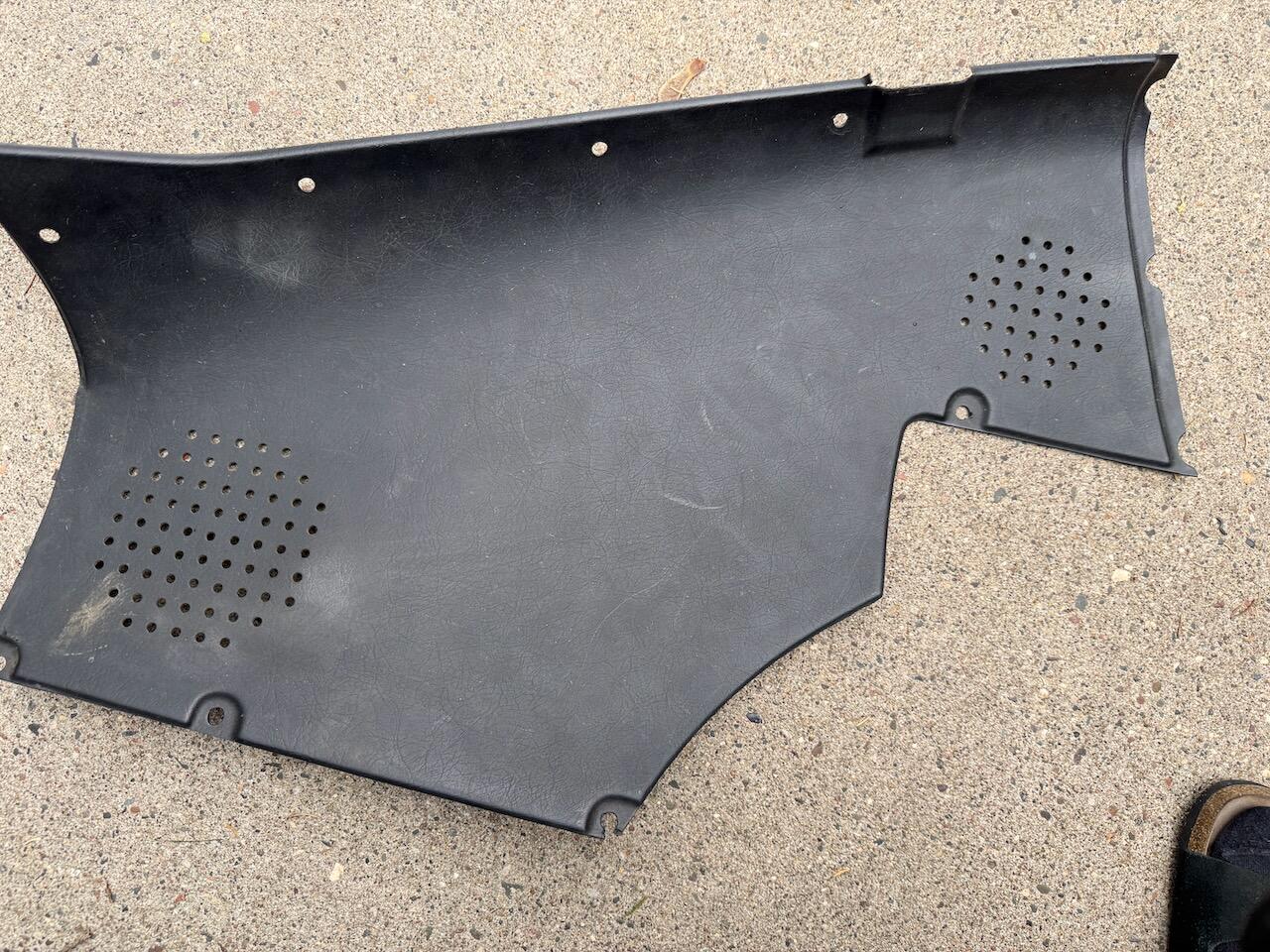
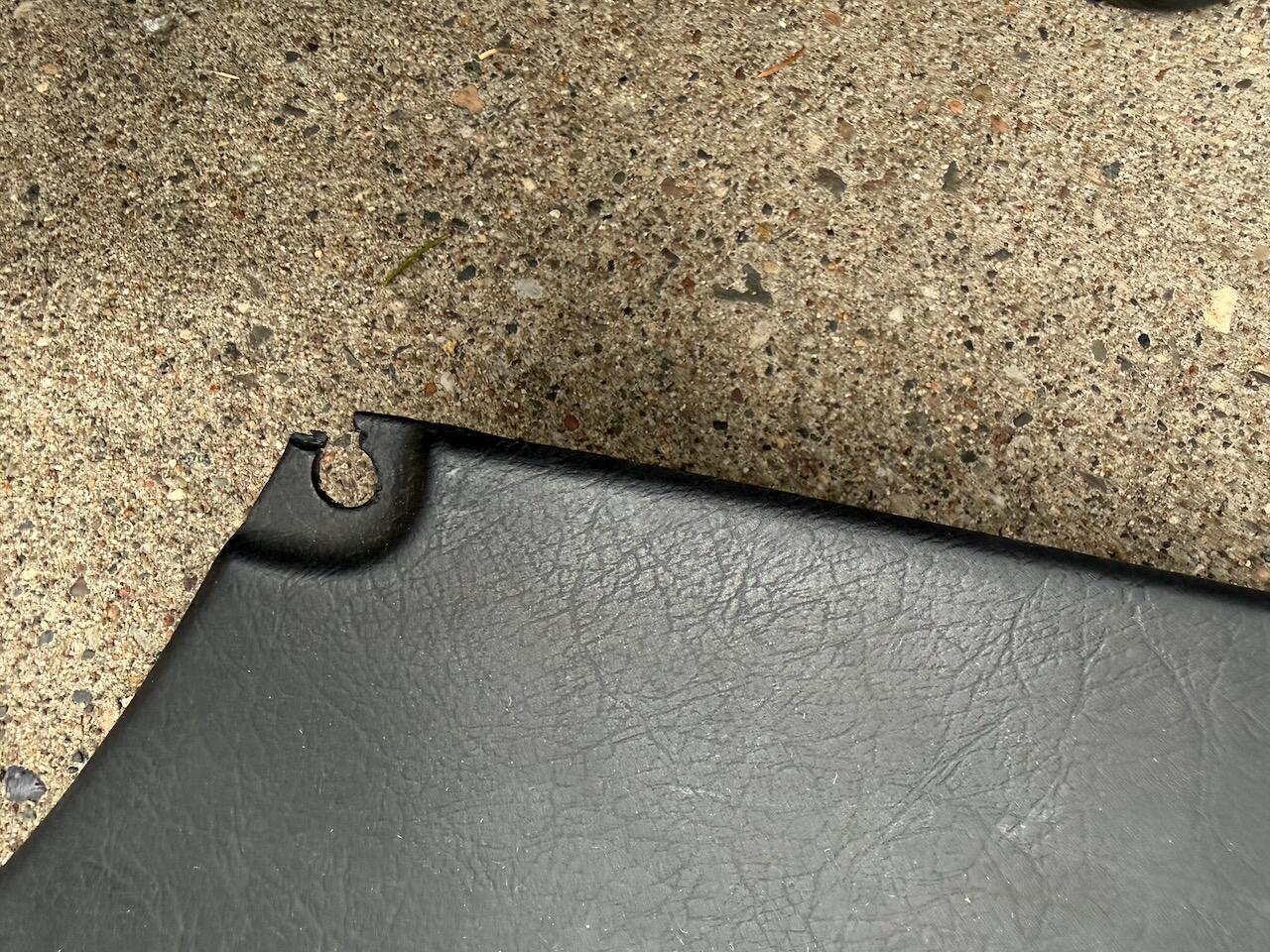
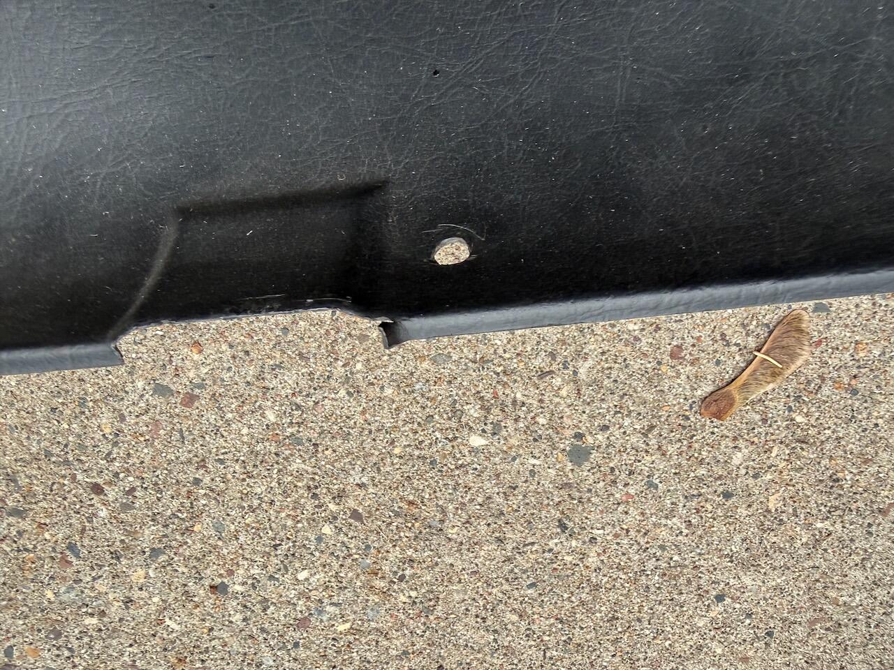
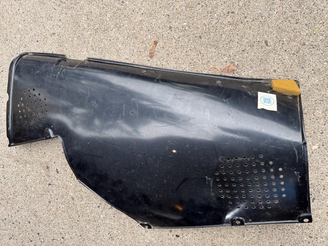
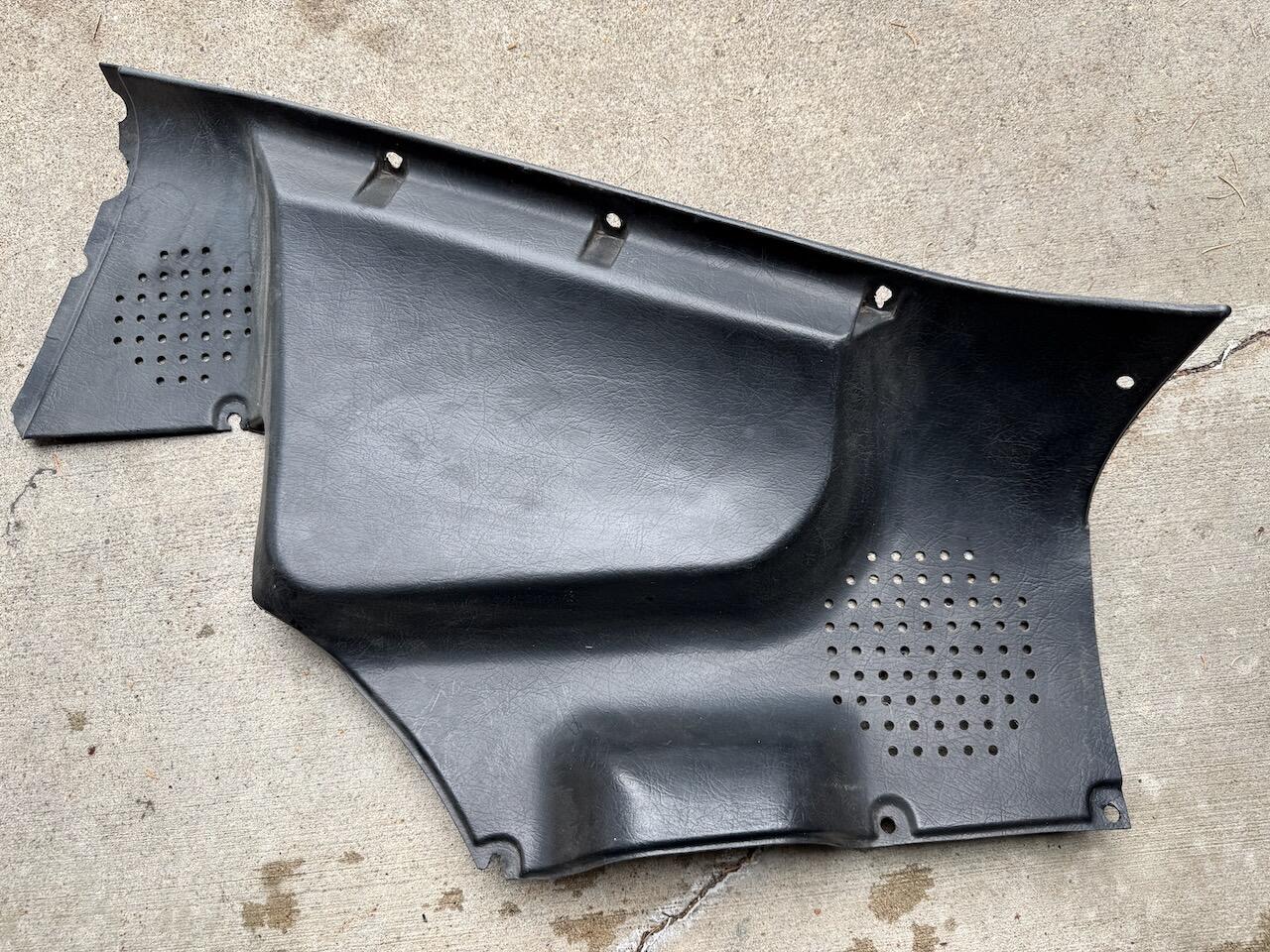
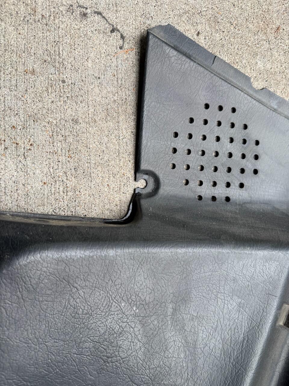
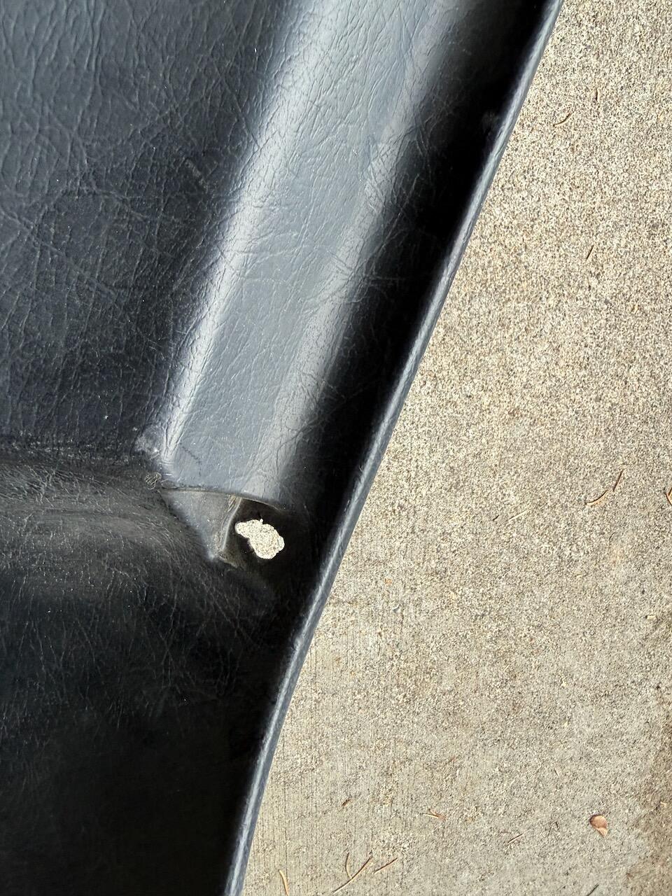
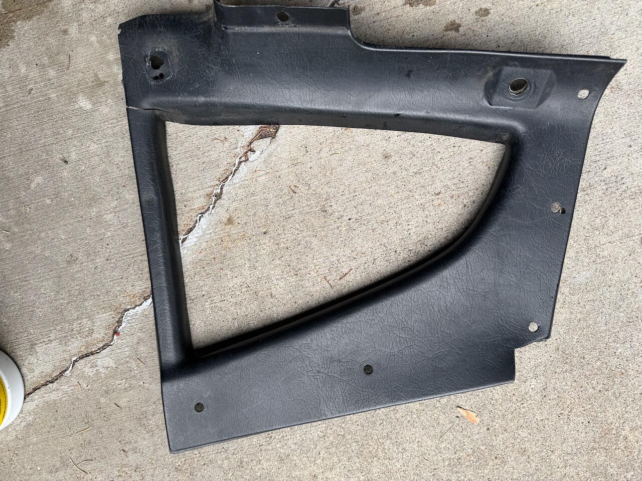
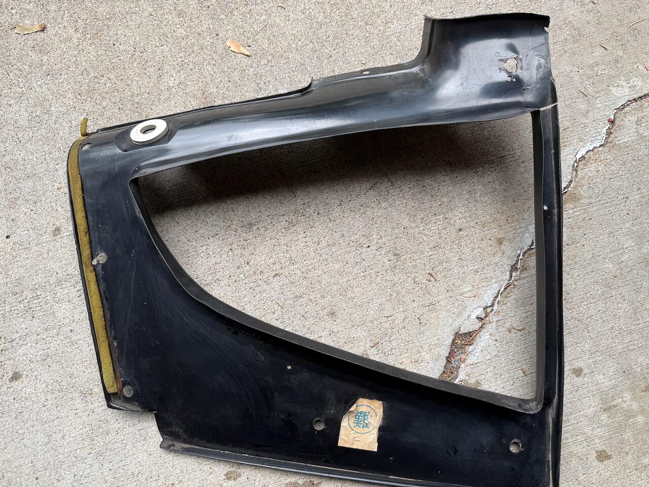
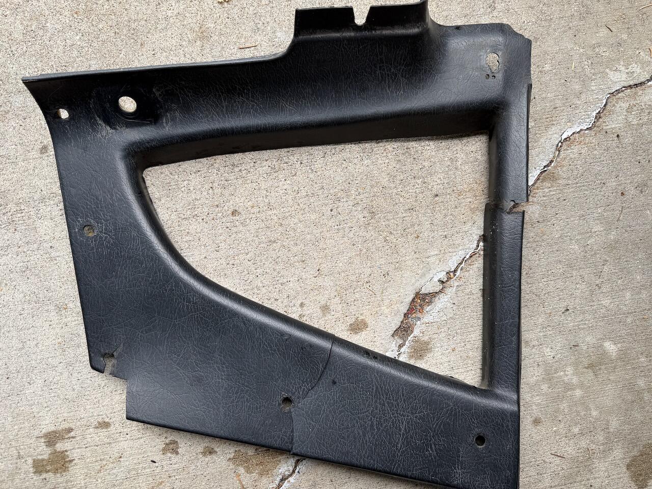
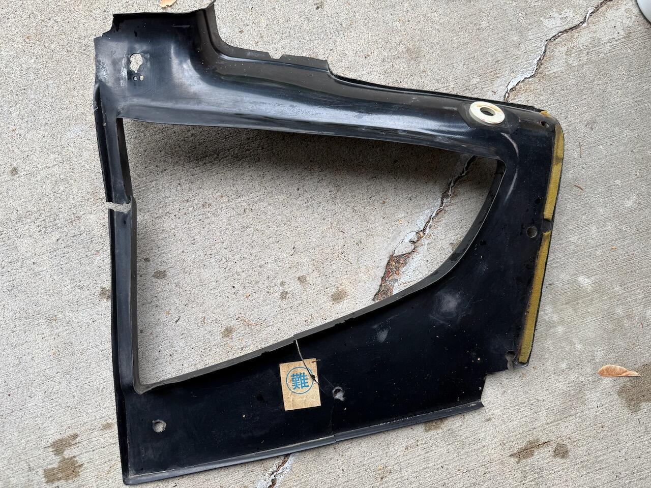
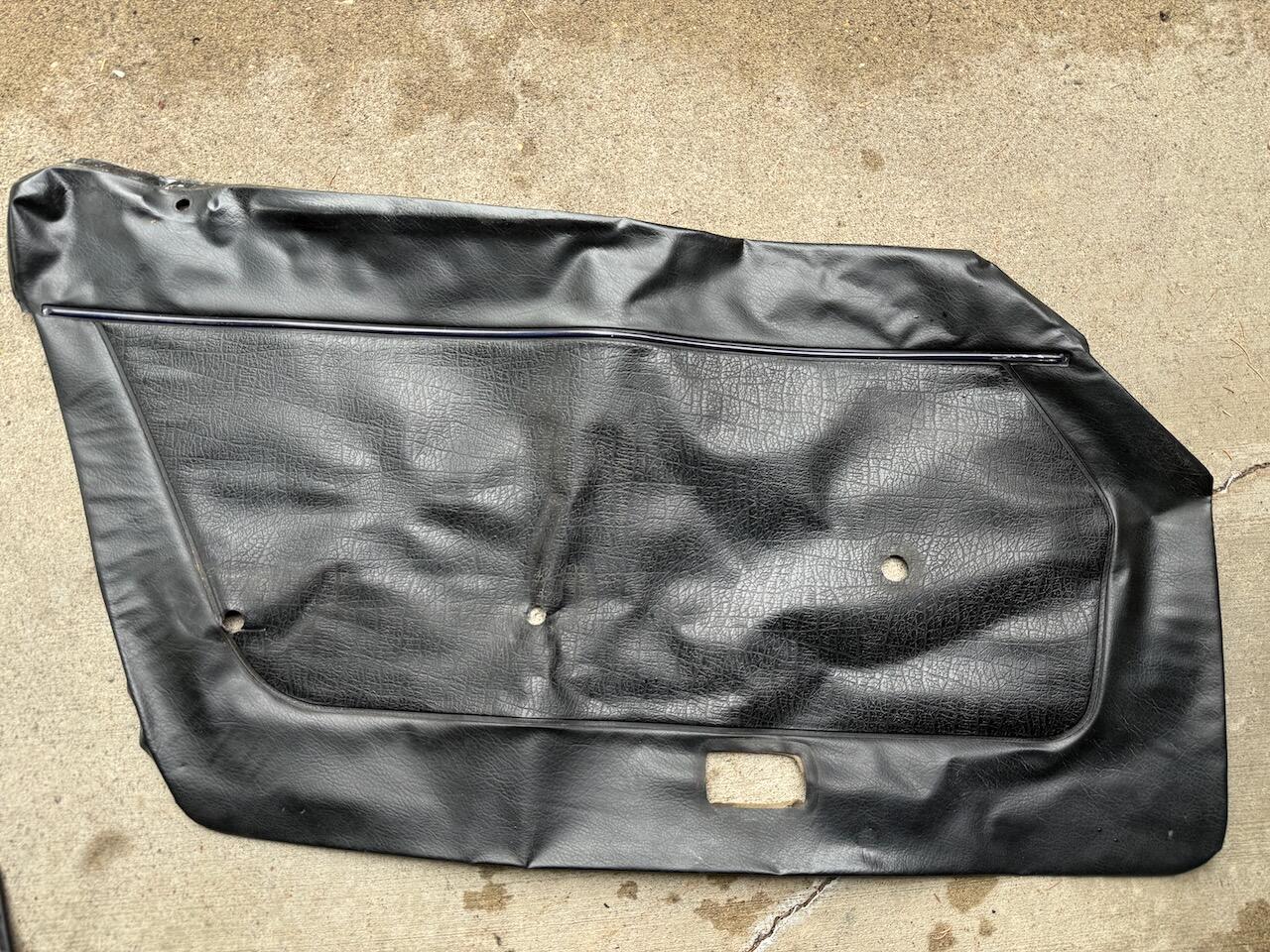
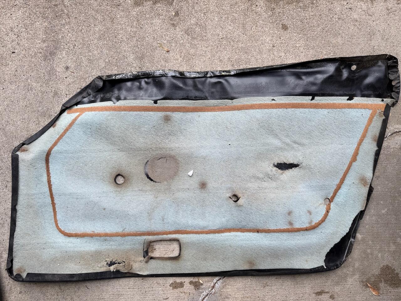
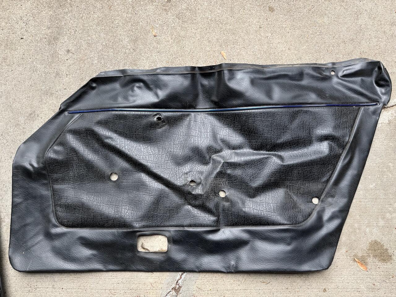
I finished the interior rebuild of my 1970 car this summer. It was originally blue, then got a 'restore' to black interior in 1991. Some of the panels are in pretty good condition, some of them are not (one of the quarter window panels is pretty bad). Door skins are ok condition. Anyway, don't consider these to be 1970 originals, that seems very unlikely to me. Free local pickup in twin cities area of MN, or I can try to ship them if you want to pay shipping. I can't imagine these panels are going to survive shipping intact. they are much thinner than the reproduction ones I put in to replace them (not saying thicker was better, made install a pain). passenger and driver dog legs Overhead plastic trim passenger and driver quarter window panel trim passenger and driver rear deck trim passenger and driver door skins (new) shift boot - this is not original style with the laces. Ended up restoring the one on the car. (new) E brake boot with snaps - accidentally bought 2 of these
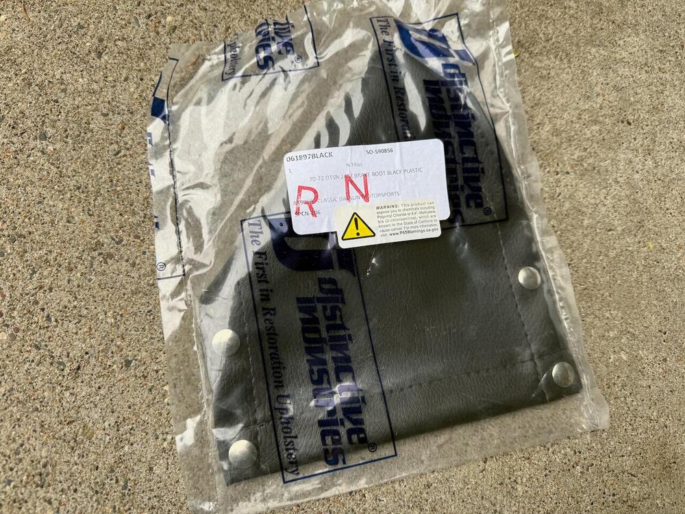
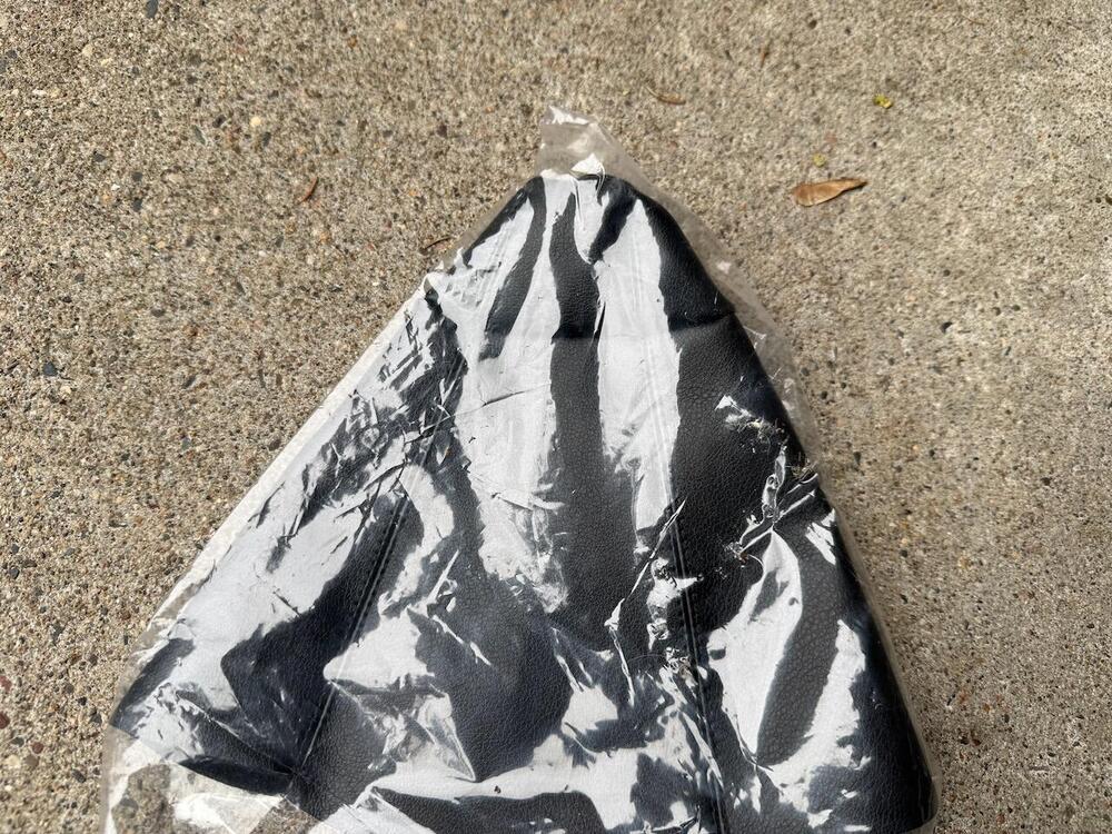
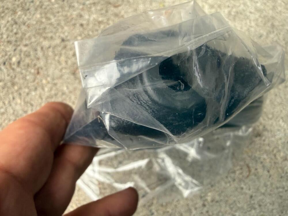
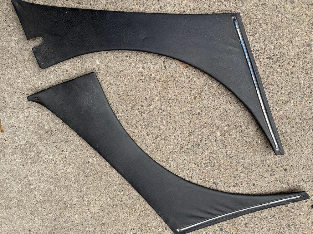
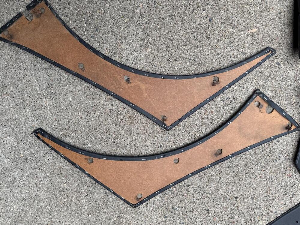
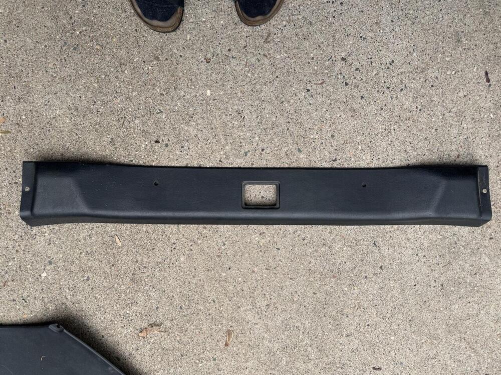
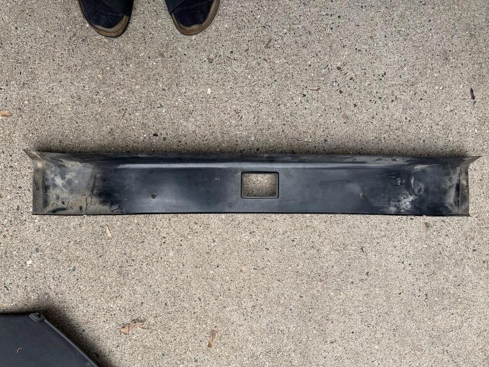
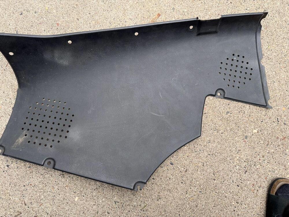
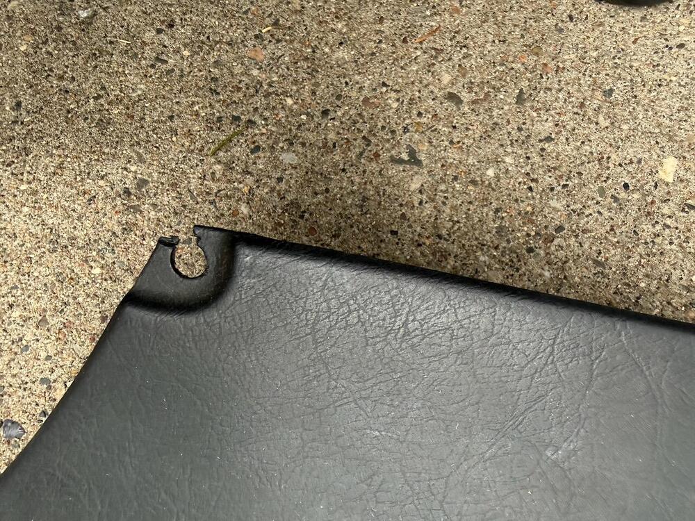
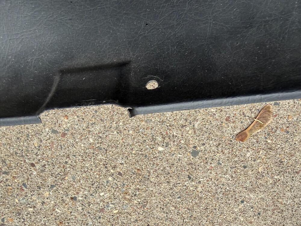
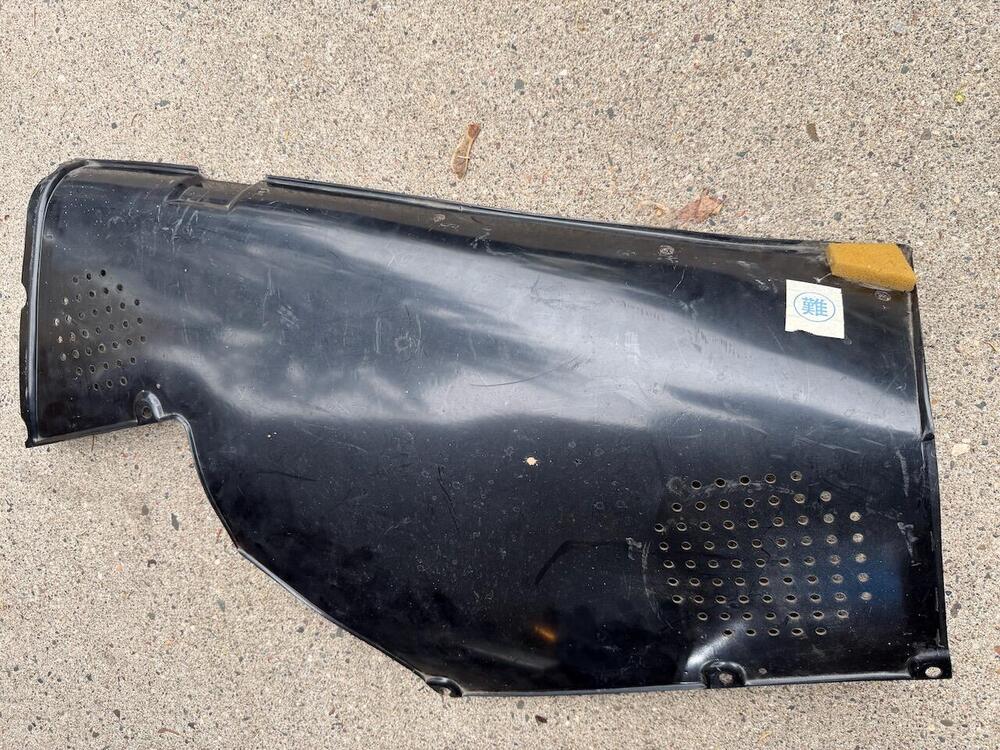
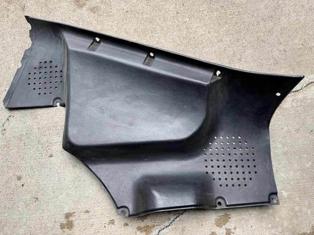
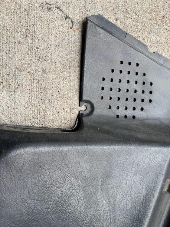
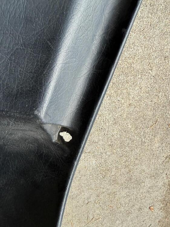
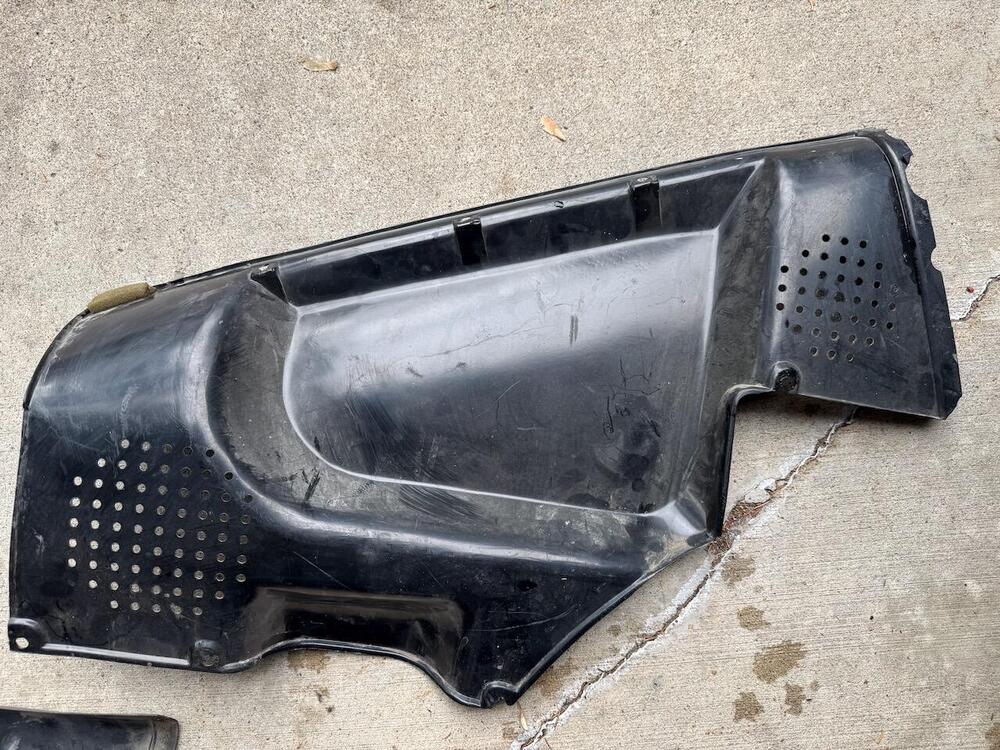
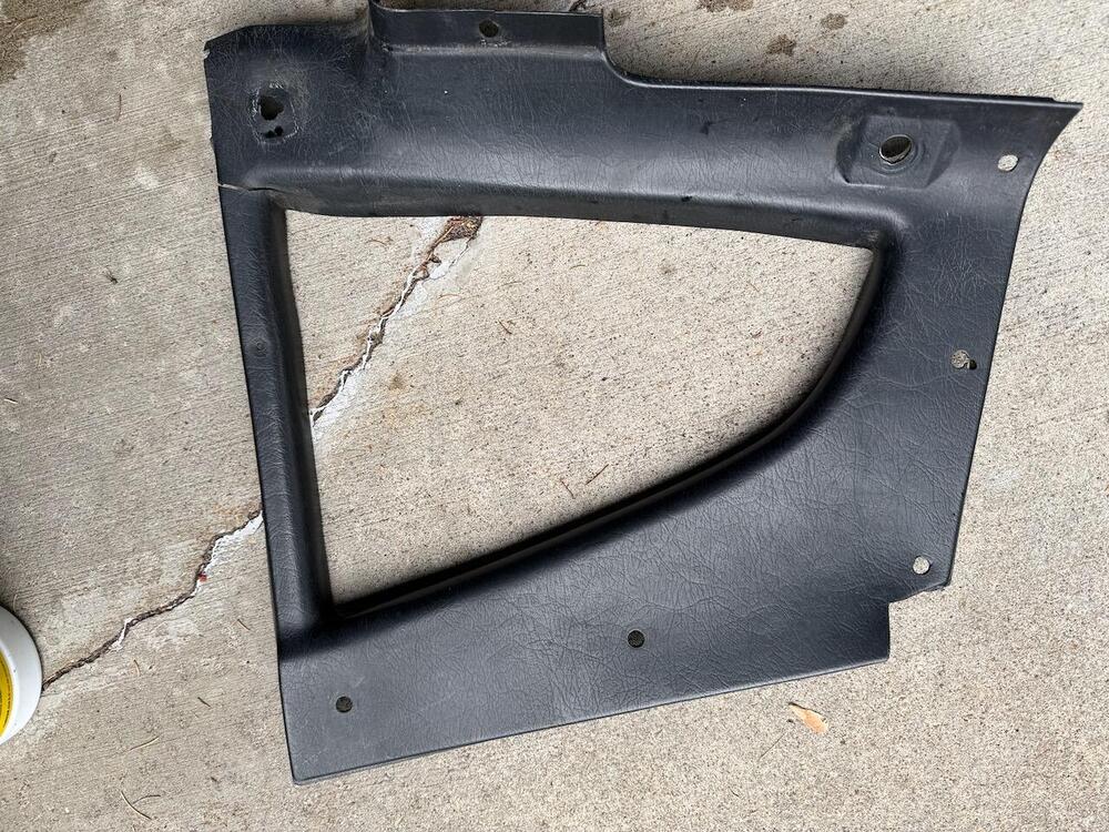
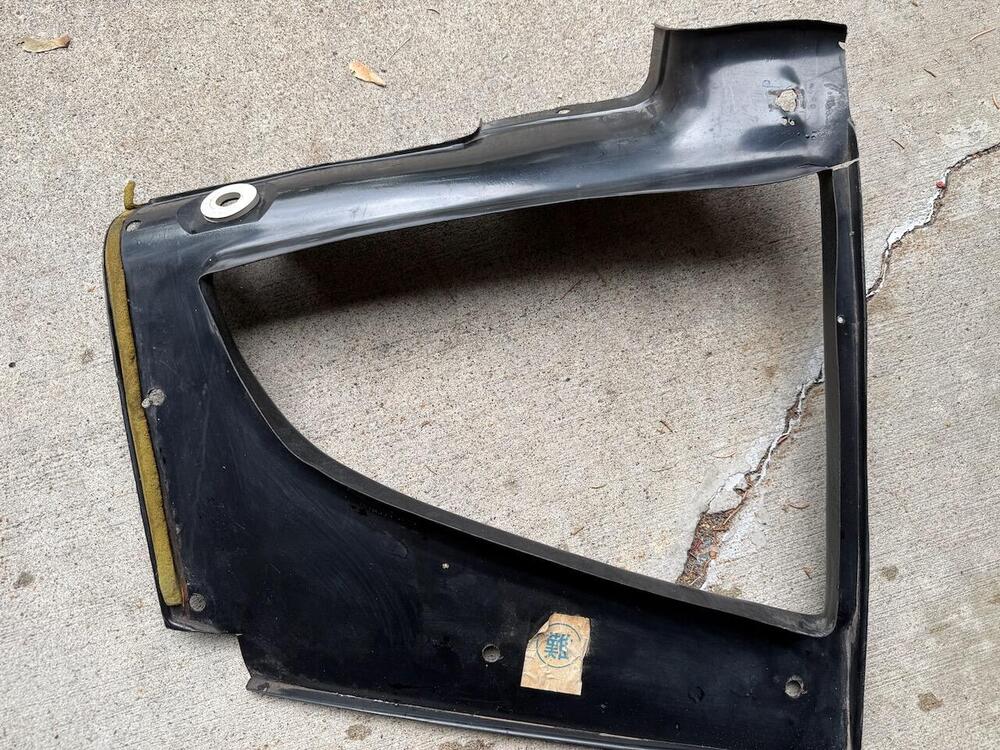

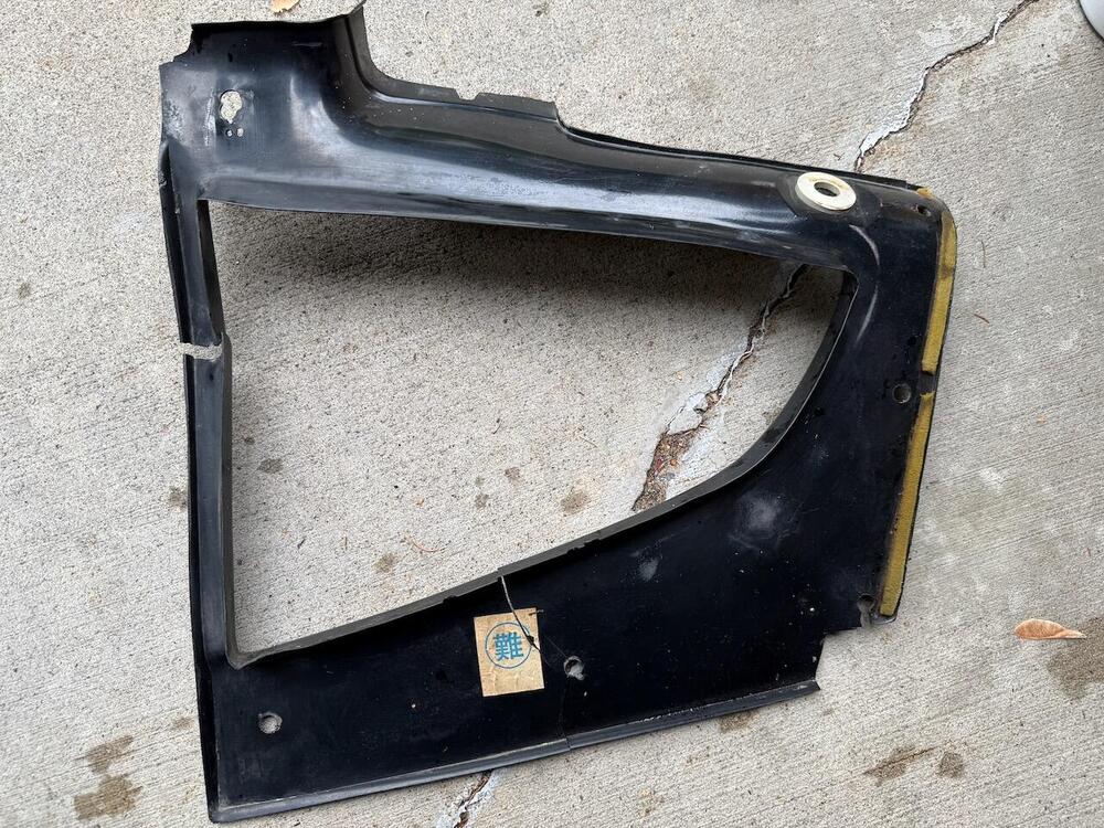
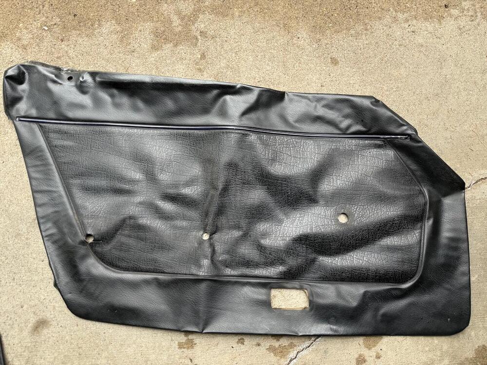
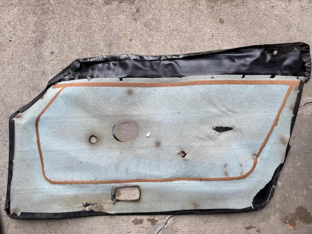
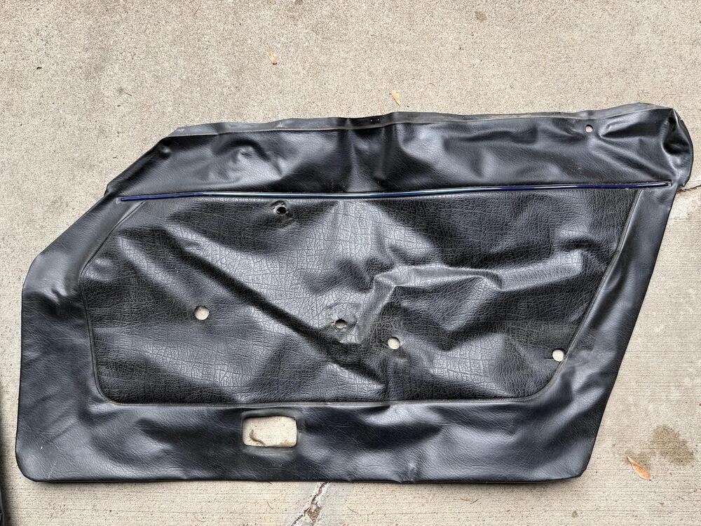
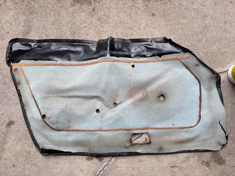 1 point
 -
I tried this upgrade years ago and while I did not have the problems you are seeing I did have one issue: my ammeter was non-responsive/dead! I reversed course and opted for a reman 60A Hitachi externally regulated alternator and new voltage regulator from Rockauto. All is well.1 point
-
Here a Datsun 240z on catawiki, personal NOT my color! But a nice restomod. (BTW. i could not put this under 240z first gen.. problem in the make a new topic so i put it in one i could!) Datsun - 240Z - 1972 - auction online Catawiki1 point
-
OK, I have rubber caps, like those that protect the threaded ends of pipes, that I can clamp onto the tranny tail prior to installation.1 point
-
No, the oil will pour out the rear of the transmission if no drive shaft is installed when it's tilted up. I would loosen the plugs on the tranny and fill it once it's in the car. They make little hand pumps that make this really easy1 point
-
Don't overlook sealing the hole at the back of the transmission before tilting the assembly for reinstallation. Avoid oil wastage. I'm sure you had it covered, but just in case.1 point
-
1 pointI ended up purchasing those one-way bleeder screws and they've been great. All you need to do is loosen and attach a small bottle on each wheel. Pump the pedal a few times, fill up the reservoir, and pump again. Repeat until the fluid is completely pushed out and clean. It's probably not as good as pushing it through with pressure or suction but it works.1 point
-
1 point
-
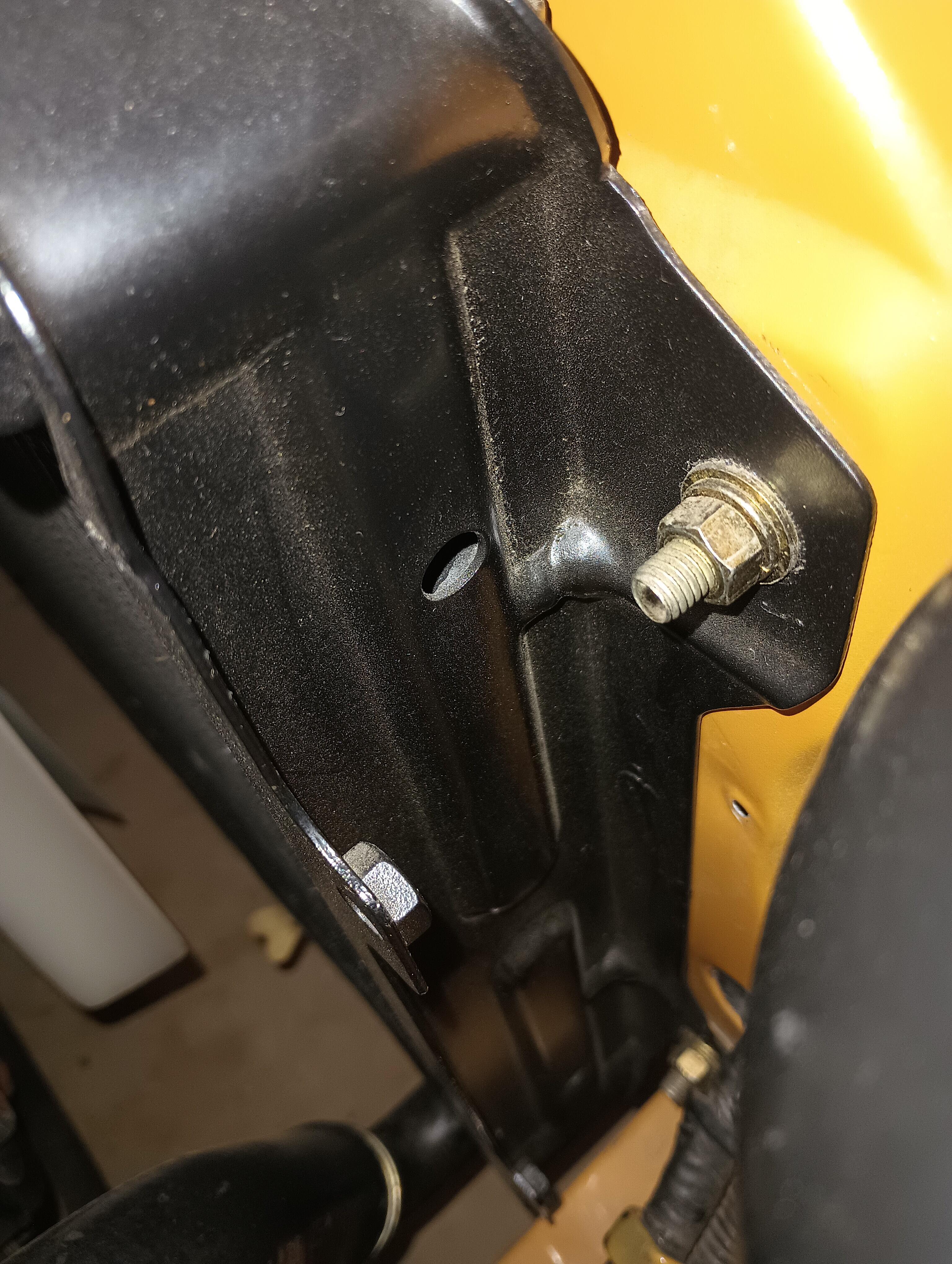
This is the right side showing a round hole, another one down low. These are tha same on the left side with the hose. This is my OE radiator frame.
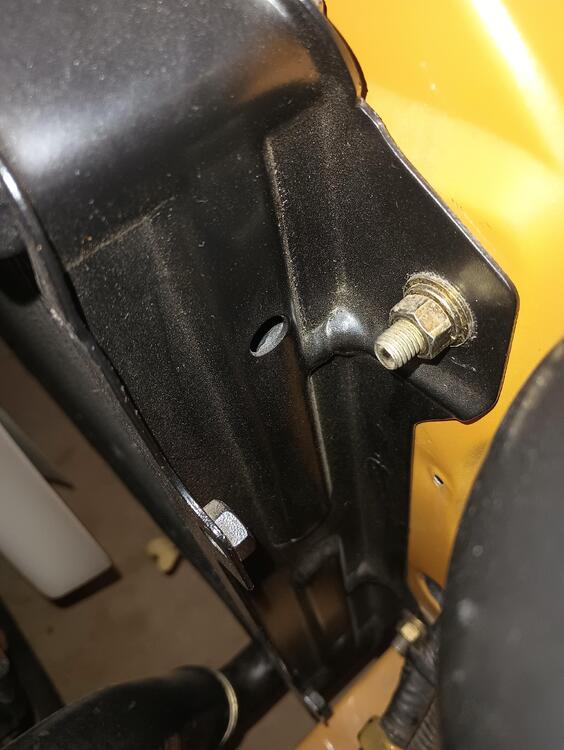 1 point
 -
1 pointWell, that took a lot longer than I thought, but alls well that ends well. I got a new MC from ZCar Depot (the cheaper of the 2 7/8th options). This one has reversed reservoirs from the one that came with my car, but flex lines from California Datsun worked great. Did bench bleeding, installed, bled the corners... brakes kinda work, but not really. tighten up rear wheel cylinders, do the whole thing over again (tried different angles when bench bleeding, for example). Checked for reaction disk having fallen. tried adjusting the setup with the pedal. everything I could think of, but still only felt solid when pedal is already half way down. Probably everyone knows by this time what it was, but it took me a long time to think of it. the MC that came with the car basically had the piston cup right up against the end of the cylinder where it fits into the booster. The new one, upon removal and examination, sits about 1.1-1.2 cm further inside the cylinder. so the pushrod wasn't even contacting it until the brake was half way down. Took out the pushrod, extended it (seemed to be pretty extendable, but a little worried I didn't keep unscrewing until I knew how long it was in there. felt solid anyway). et voila! brakes are firm. Went for first "joyride" in 8-9 years. all of 3 blocks away before I turned around and came back. the shock bump stops crumbled to dust and I'm still waiting on new struts from MSA. Don't want to hit any bumps too hard. Now for a nice water free wash.1 point
-
1 pointI have watched some you tube videos about similar chassis, such a the FJ and the celica. The discrepancies and problems compared to factory chassis' were really bad and not insignificant1 point
-
1 point
-
1 point
-
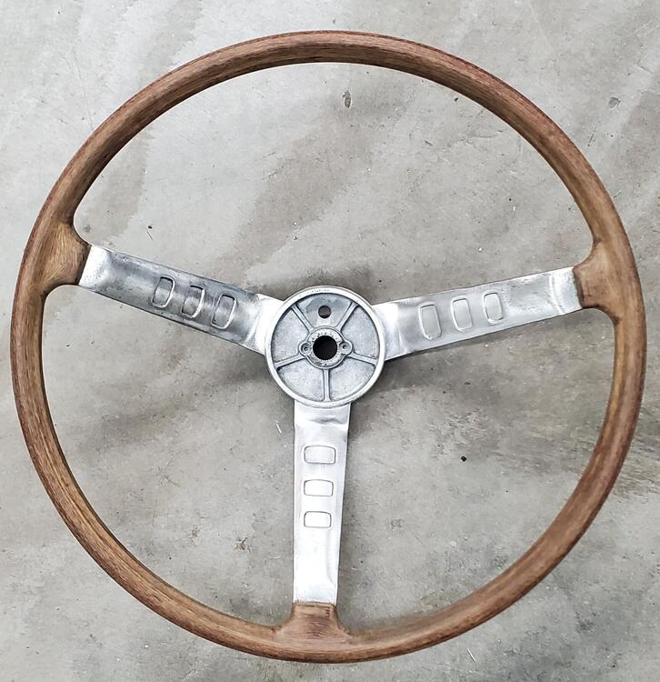
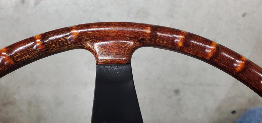
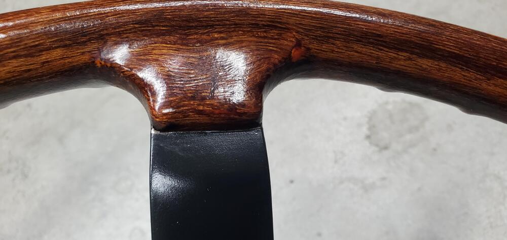
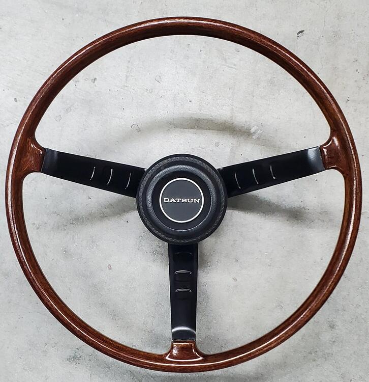
1 pointBeen busy at work so just a little time in the evenings. I have been working on the steering wheel and am pleased with the results. I stripped the spokes to metal and painted with 2 light coats of VHT engine primer followed by 3 coats of VHT engine GM satin black enamel. I then sanded the rim smooth and finished it with 600 grit and 00 steel wool. The spokes were prepped with acetone before painting and the rim with isopropyl alcohol. I coated the rim with 3 coats of Helmsman Spar Urethane in warm semi-gloss. One light and two medium coats until it flowed smooth with about 20min in between coats. I kept it moving the whole time spraying in my hand and immediately used the hair dryer for a few minutes on high heat, low fan to set the application so it didn't slump or run (just in case). Ambient air was 72-76 degrees F and around 50% humidity for all the days. The color is just the wheel with no stain. It really is a beautiful thing, this 240z wheel. I love its simplicity
 1 point
 -
1 pointUmmmm..... Yeah. You have a car hobby, so good luck with that. Hahaha!!!1 point
-
Now, the more complicated... The nozzles should not ever stick in the holder. If they are doing that, you need to figure out what is going on with that before you move forward. I've seen grit in the nozzle holes. Grit in the actuating mechanism. Burrs on stuff. Varnish on stuff. Plating too thick interfering with stuff that should rotate. Plating flaking off and becoming grit. Lack of lube where necessary. Incorrect needle alignment. Incorrect assembly of the little springs... But the point is, you need to make sure the nozzles return to full UP home when the choke cable isn't pushing them down. And can we work on the adjustment of the throttle plate opening amount when you get the rest of the stuff under control?1 point
-
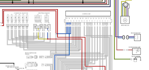 This is a wiring diagram created in Adobe Illustrated and saved as a PNG file. It is a large graphic file. This does not include California specific or Automatic Transmission specific components. This is for Federal, Manual Transmission, and Factory Air Conditioned 280Zs.Free1 point
 -
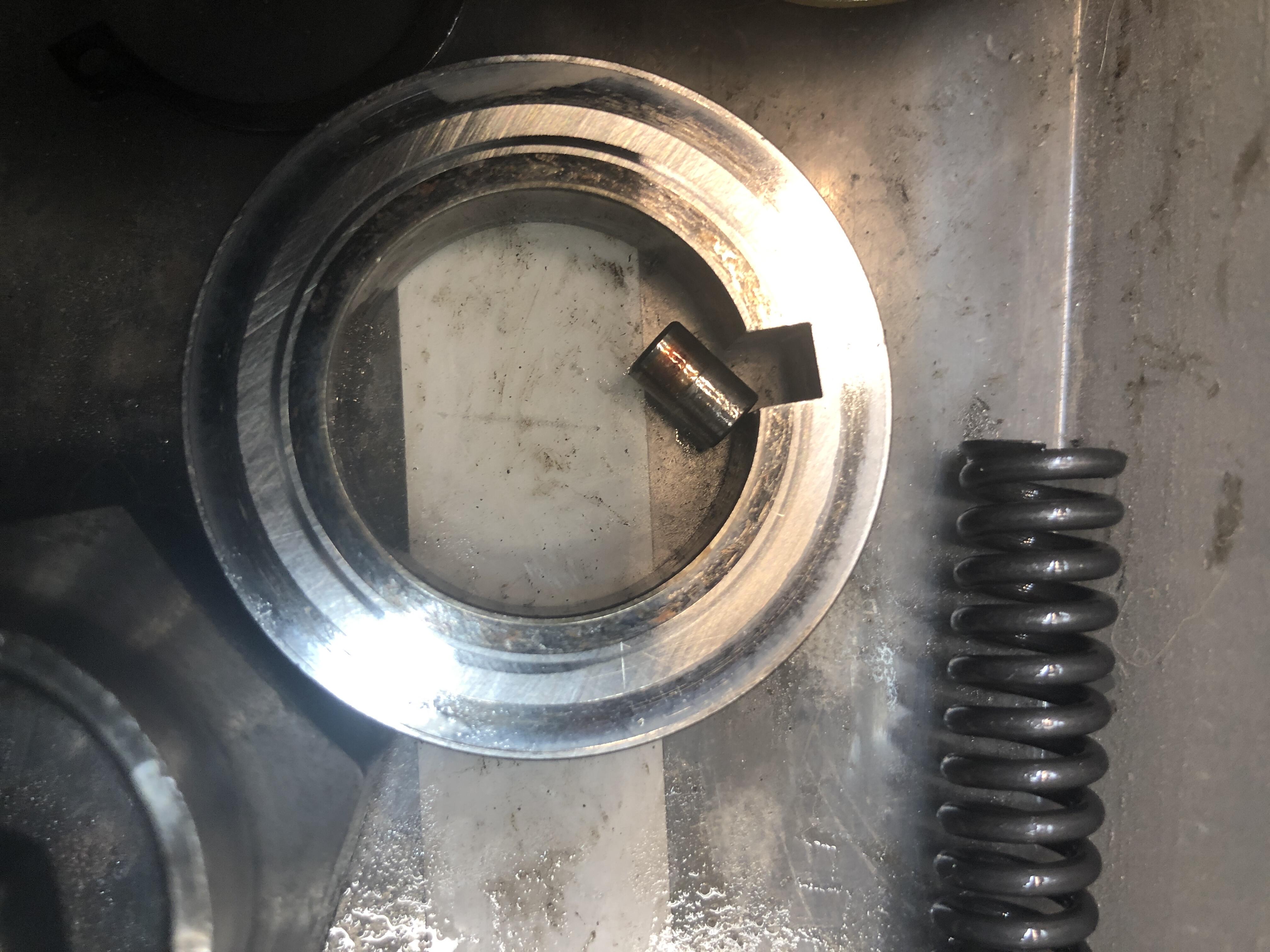
Now in the next trans revision, this was apparently a known issue because , here is what they did. Big fat pin and much larger slot in the washer.
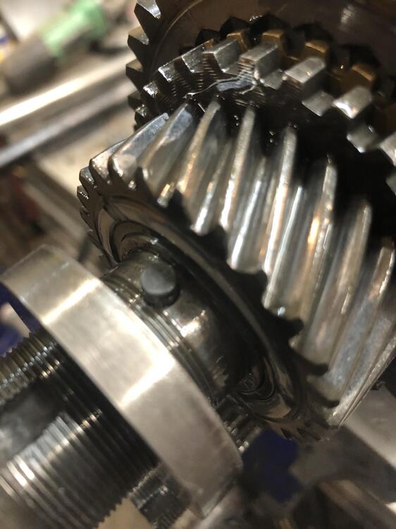
 1 point
 -
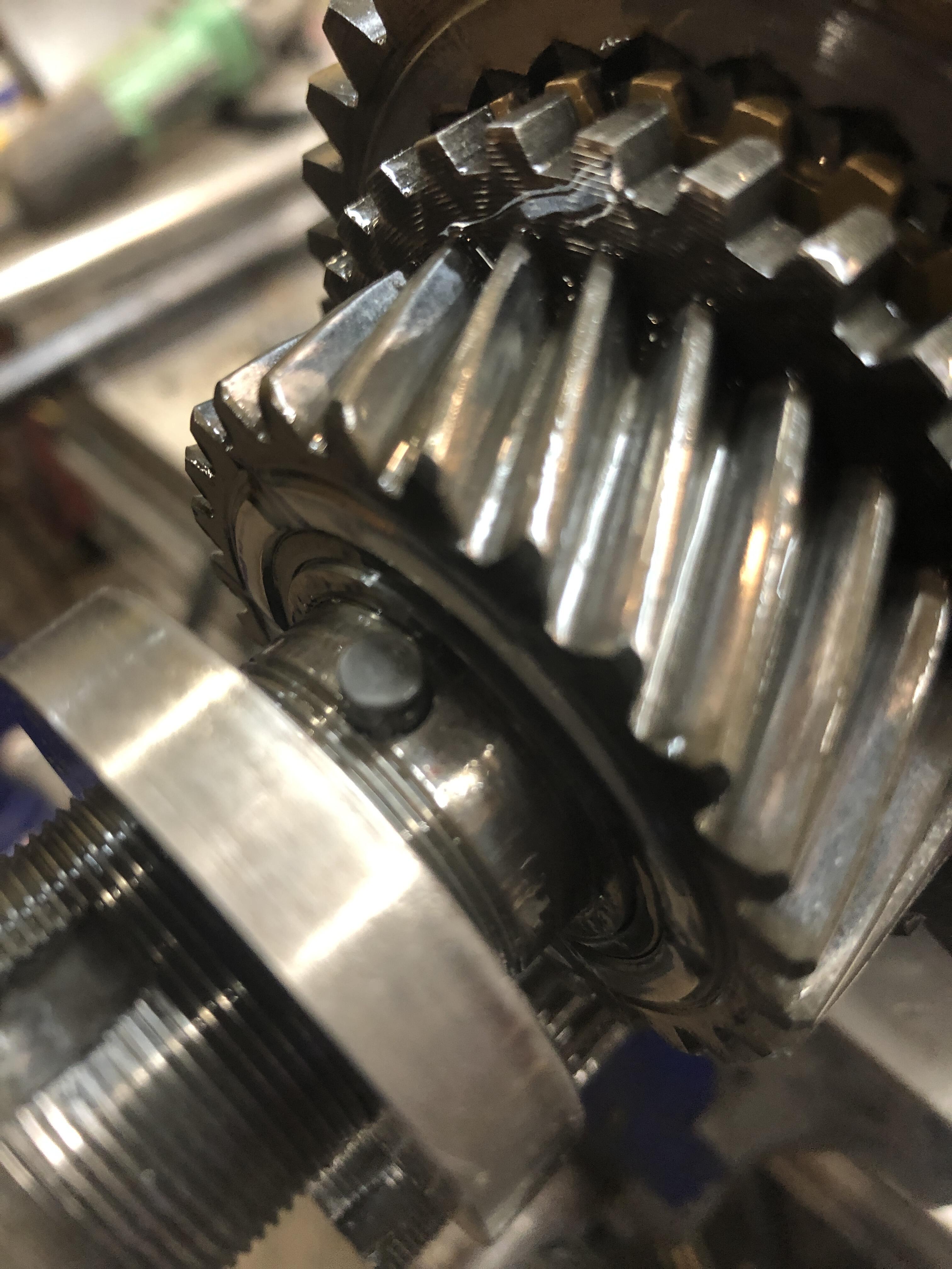
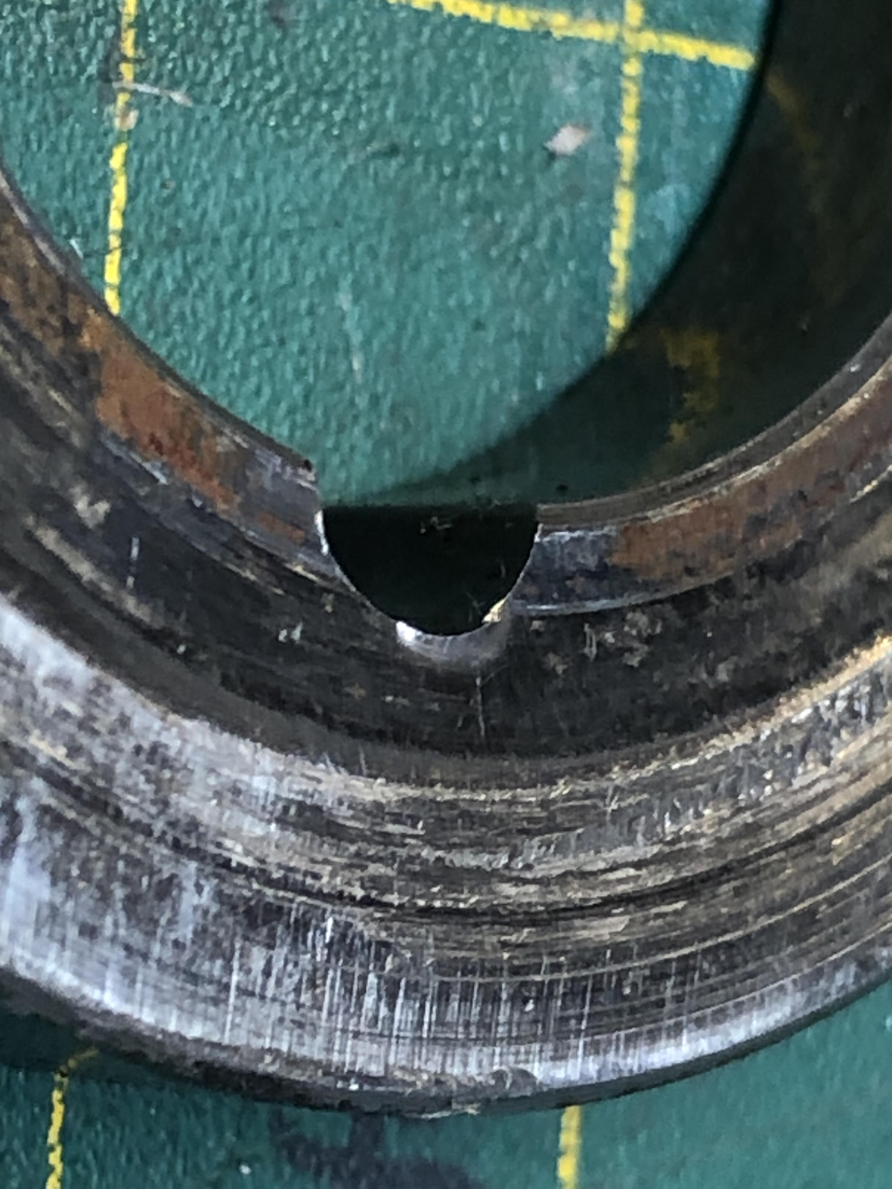
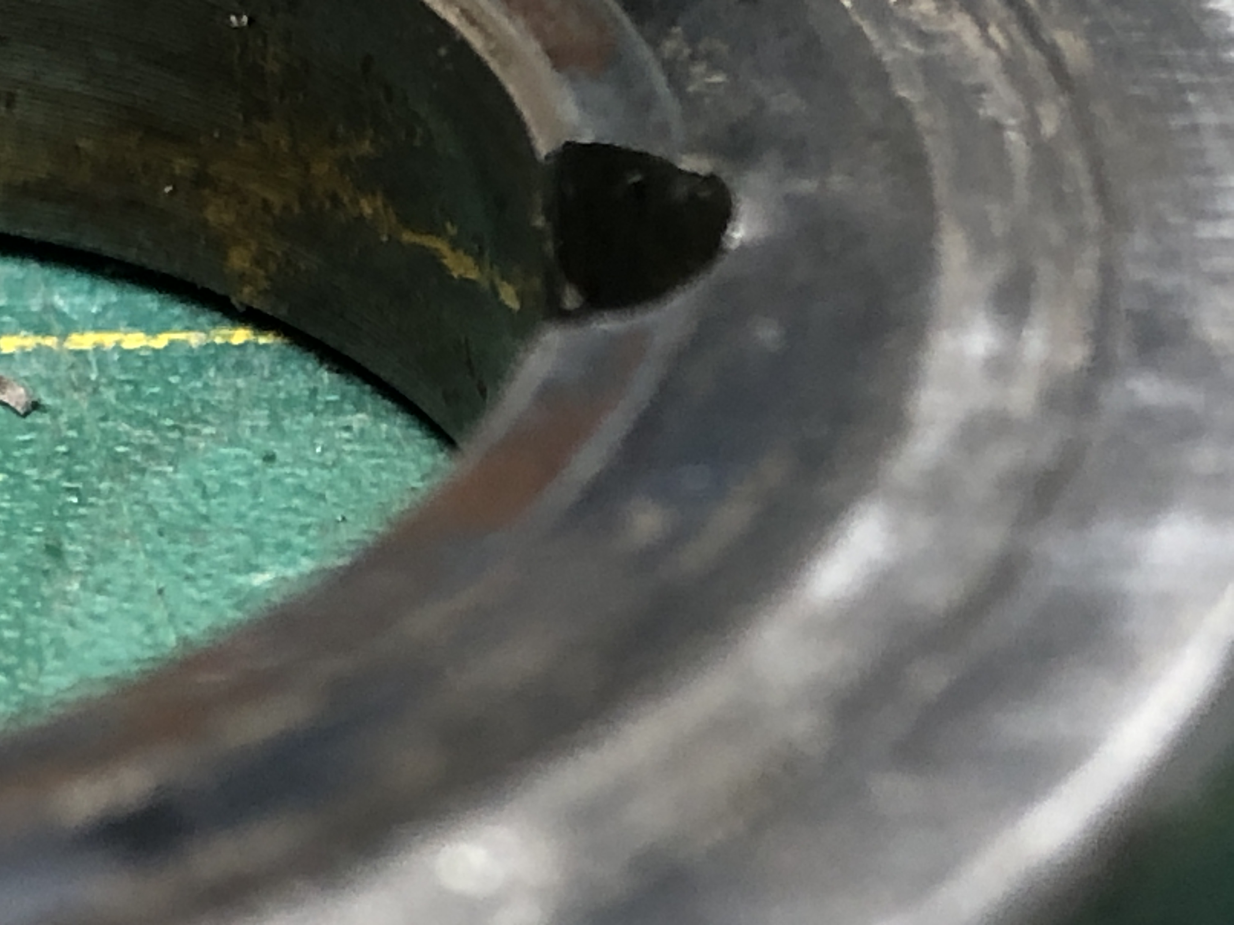
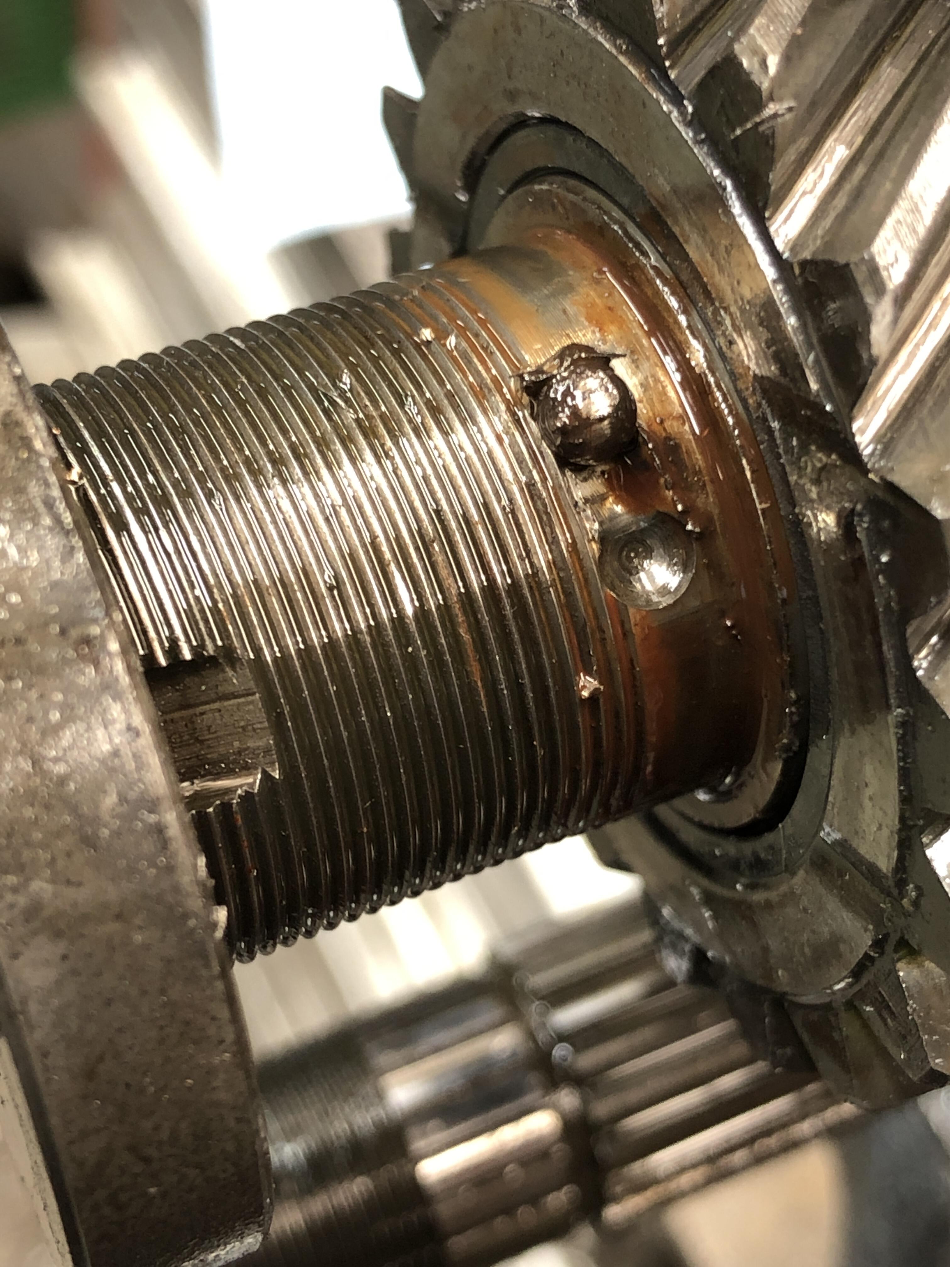
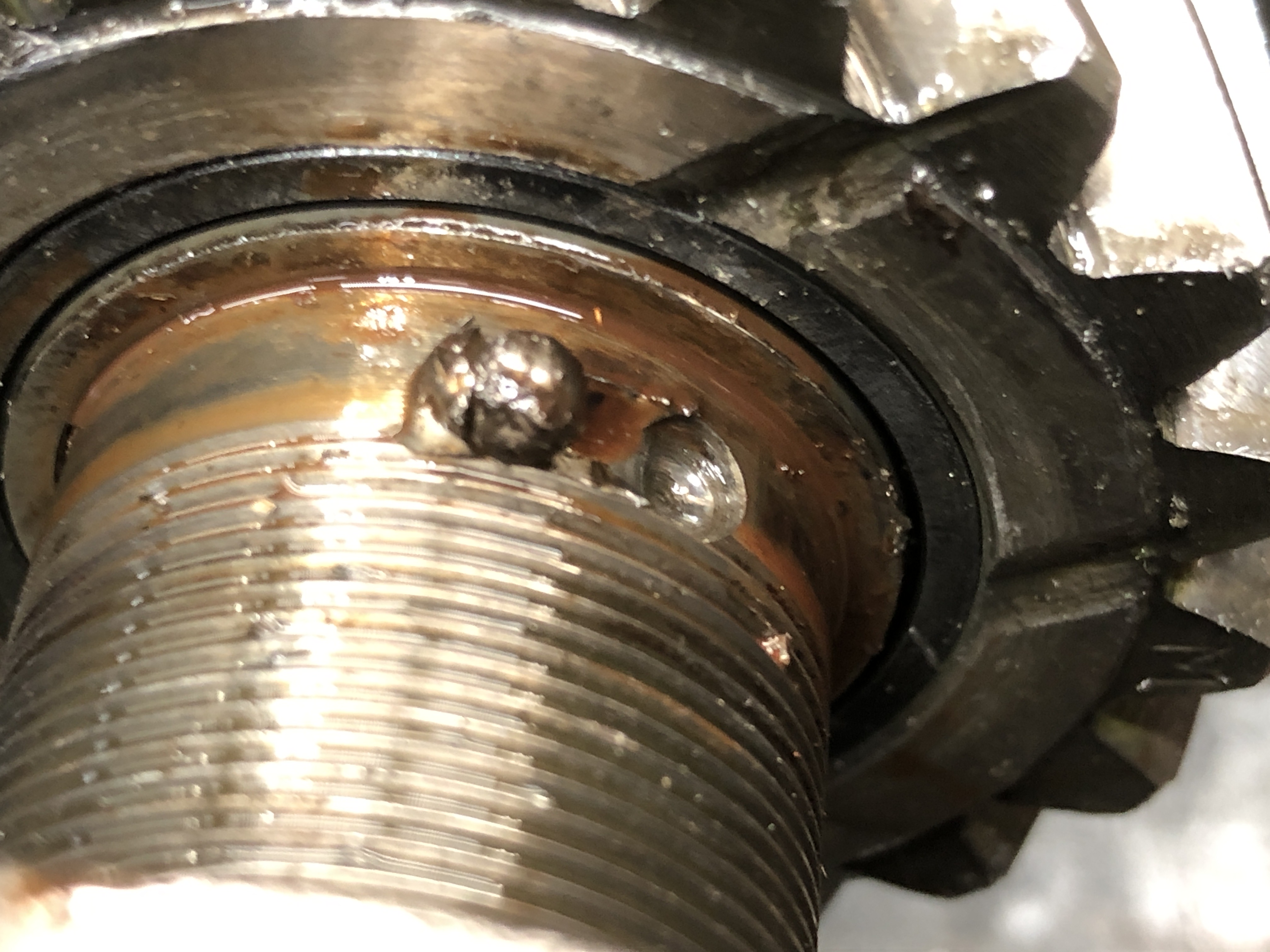
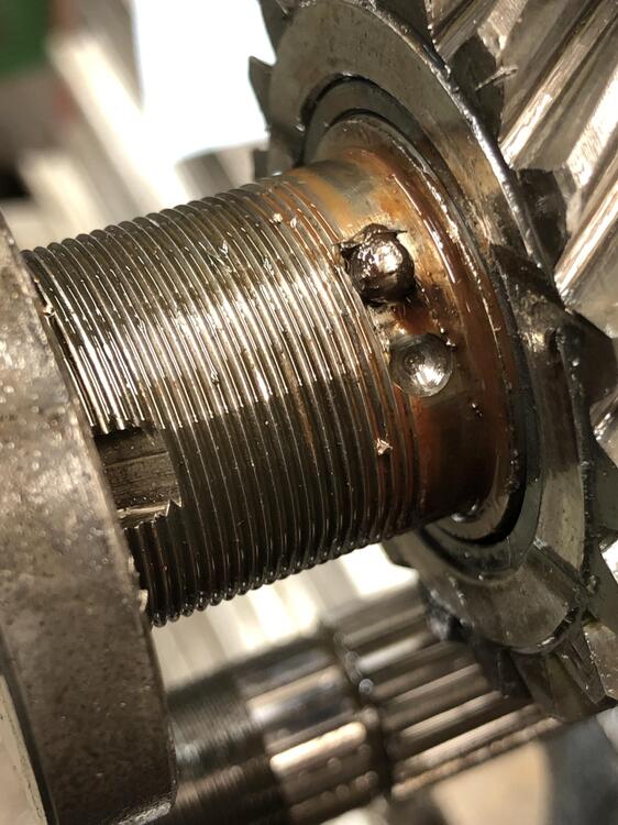
Seems the little ball decided to try to leave home for greener pastures. In doing so, it deformed the groove in the washer, causing it to lock against the gear face next to it, effectively locking 5th gear to the main shaft. Usually it hits the sleeve under there where the sleeve bearings run, and not touch 5th gear. I hope you can see the deformed area at the top of the groove arch. This is enough to touch and lock quite solidly against 5th gear.
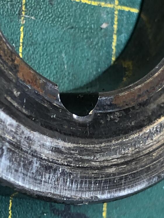
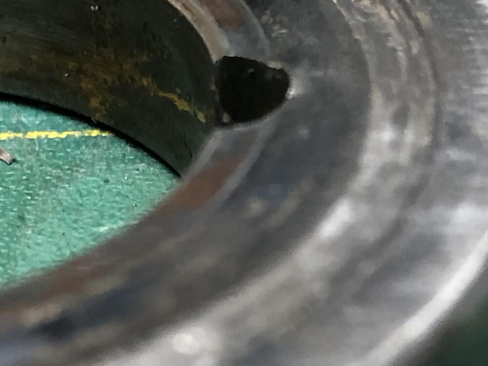 1 point
 -
The tranny was indeed locked up. Nothing that you can see on inspection of gears, syncros, shift rods etc. Trans shifts ok into every gear except 5th. My first guess was a loose big main shaft nut. Nope. When in neutral, you turn the input shaft by hand the output shaft turns and is hard connected to the output. Oh oh. Something under one of the gears or synchros has a failed (sleeve bearing?) and is not allowing each idler gear for each speed to spin free in neutral. Hmmmmmm Well, start at the back end and start to take 5th gear apart. Get the big nut off (it was still staked and tight), and then try to slip off the fat washer behind it. No move-y. Get a hammer. No move-y. Get a chisel to get between that washer and 5th gear. Hit it. No move-ness. Nada. This is the one with the little ball and groove that prevents it from moving. Well after using more and more “assistance”, the washer finally comes off. And what should I find? Behold
 1 point
 -
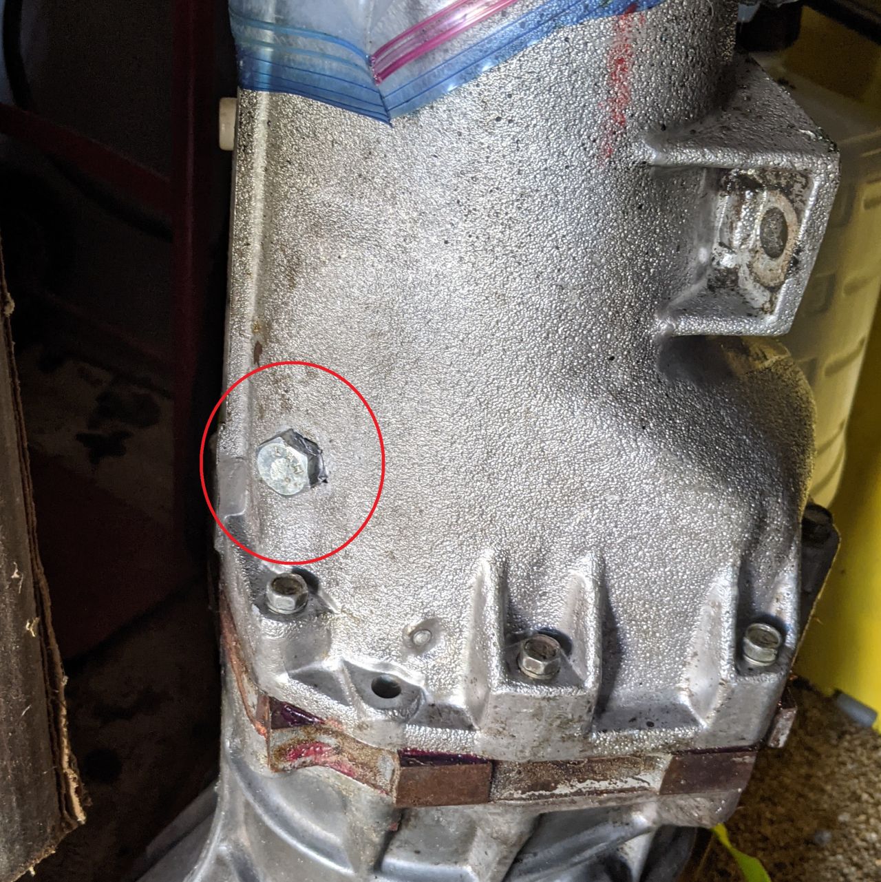
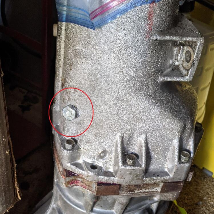
Here's what my transmission looked like after adding the access hole.
 1 point
 -
1 pointWell it’s not my proudest moment but it’s out took a 90 degree drill and lots of bits Sent from my iPhone using Tapatalk
 1 point
 -
1 pointFor the 73 Model Year Production of the 73 Model Year 240-Z for the US and Canada started in 08 of 72. - Carb.'s changed (as mentioned) - different E-88 Head Used For Federal Emissions Std.'s in 73. - Dash layout changed, with backlight heater/vent controls, - new hazzard switch design. - Headlight buckets changed from fiberglass to steel. - Flame retardent materials were required for interior use. - Intermitten windshield wipers added as standard equipment. - Two and a half mile per hour bumpers added. - The rods were the same - but larger connecting rod bolts were used. 8mm vs 9mm This actually started at the 2/3's of the way through the 72 Model Year Starting at Engine Serial Number: L24-096181 That would be in US/Canada 240-Z's with a build date starting in 04 of 72. FWIW, Carl B.1 point