Leaderboard
-
z8987
 Subscriber
 18Points348Posts
 -
.JPG.cfcada9cf1c1b502df3f5f2f2ca3ff36.JPG)
SteveJ
Free Member12Points9,685Posts -
CW240Z72
Free Member9Points229Posts -

siteunseen
Free Member6Points15,175Posts


Popular Content
Showing content with the highest reputation on 01/22/2022 in all areas
-
I did the rapid test at my physician's office this morning and the results were negative. Never have I been so happy to go back to work! Initially I had the PCR test that came back positive so I quarantined for 10 days and had another PCR test. Still detected Covid. Then I talked with my pharmacist and my doctor's PA. They said the PCR would show the slightest amount for up to and even beyond 4 weeks. So the lesson here for me, to get the negative result, was after your symptoms are gone and you've done the 10 day quarantine get the rapid antigen test. The free money days are over for Covid and I have a mortgage plus a Datsun diZease. This turned my world upside down for almost 2 weeks and I was only sick for 48 hours. The dead giveaway for me were the night sweats so pay attention to that and keep your mouth shut. It's hard not to talk about being positive but not something you really want to share, at least for me. People are scared.6 points
-
5 pointsI’ll try again. I’ll start a new thread and let this one die. DatsunZguy, I’ll try again, take your time to get to know me and why we are here. Boasting is not my character5 points
-
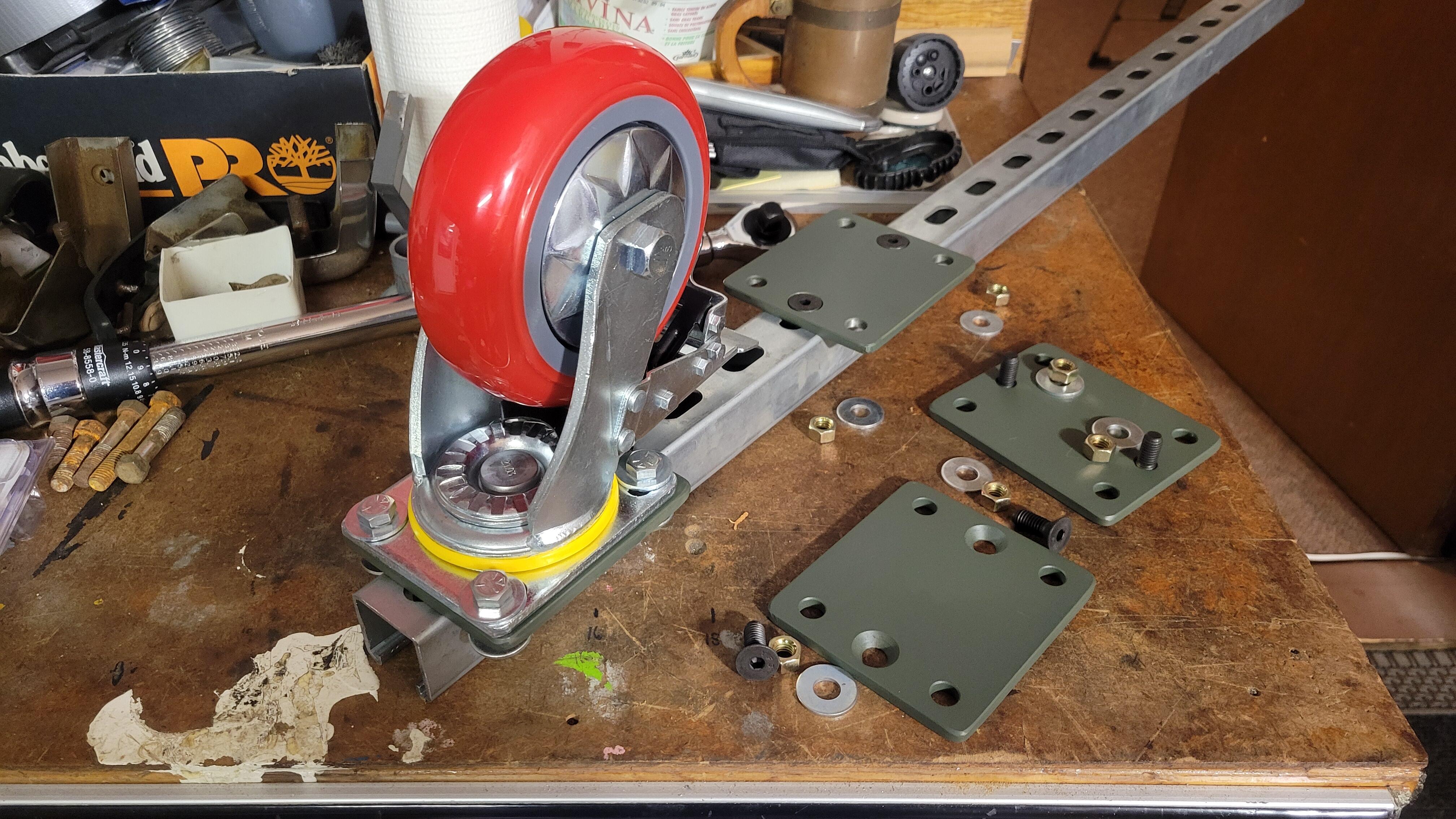
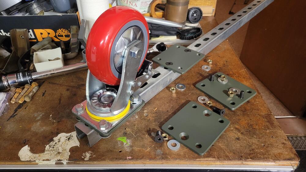
3 pointsWelding is the typical method for something like this, besides not having a welder, I just wanted to try something different. Bolted does offer other benefits, like allowing for easy adjustments or reuse for another project. Great idea your friend had on the wood frame rotisserie, I would like to see a picture of it in use. People tend to work with materials they are comfortable working with. I wonder if he is a member of the local club I'm part of, the BC Z Car Registry. Also late yesterday I picked up the caster plates that I had a friend make. This was the only part I had to actually make for this project, I gave them a quick coat of primer last night and did a test fit this morning. My son will be helping me with final assembly tomorrow. I neglected to tell him that part of job was helping me clean up the garage as well. Lol
 3 points
 -
What? Do you think I can just spit out a response? 😉 I've been working on it for about 45 minutes now.3 points
-
3 pointsThat's child cruelty. 😉 By the way, I used to have a bench that was just about the height of the door sill. I could lie on that while reaching into the driver's footwell. It was much nicer than just throwing a blanket over the door sill while I was trying to maneuver the cotter key into the clevis pin.3 points
-
3 pointsShame to see this thread go off the rails. The 'no' response was a bit curt, but whatever, not a huge deal. As for boasting, I think that's ridiculous. OP got himself a nice car and was excited to share, is that not what this forum is for? I think it'd be good if a mod would prune this thread back, and we could all just move on. Would be good if OP would put his pics back up. Just ignore the guy complaining.3 points
-
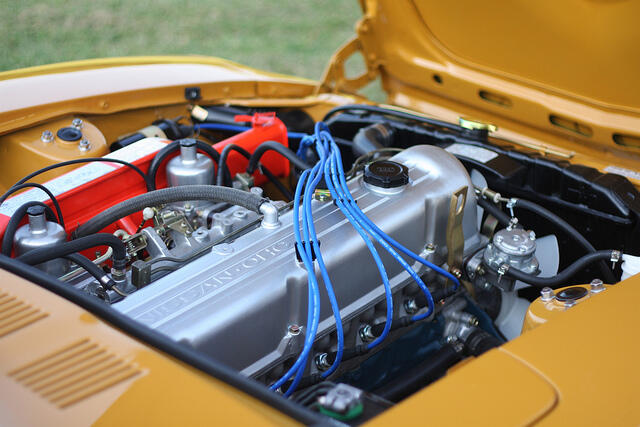
2 pointsEngine compartment and wheel well cleaning What it would look like to get a flat in 1970. I’m using simple green to take off the layers of grime. I used a plastic scraper on the thick stuff on the struts. It takes the paint off. I started using a plastic brush, it works but the thick stuff is a problem, any ideas on a better way to remove the thick grime?2 points
-
You are welcome. I just ask that you pay it forward to others when you have the chance.2 points
-
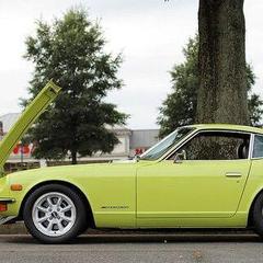
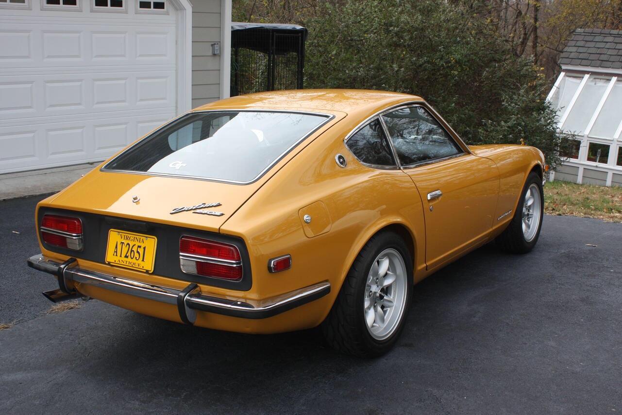
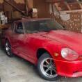
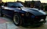
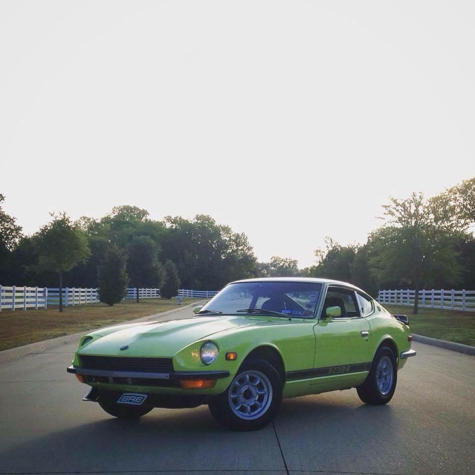
2 pointsGreat looking 70…..let me boast a little and show you mine LOL. Jim @jfa.series1has one he can show you too!
 2 points
 -
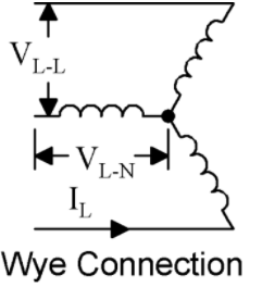
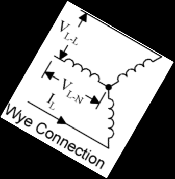
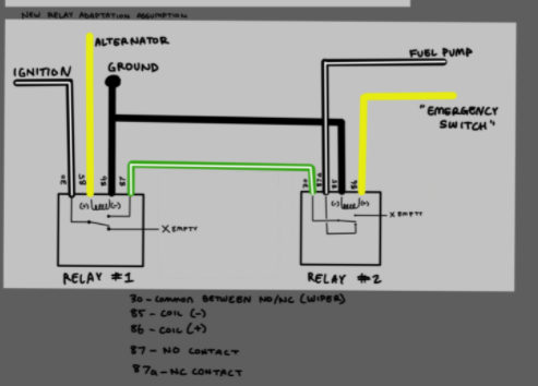
Let's go over the theory of operation in an effort to help explain what is going on. When Nissan changed carburetors between the 72 and 73 model years, more complaints were received about vapor lock. Nissan implemented a couple of "fixes". Insulate the heck out of the fuel rail including the individual hoses from the rails to the carburetors. (Mmm, asbestos!) Add a helper electric fuel pump to the mechanical fuel pump to push cool fuel through the lines blocked by the higher pressure vapor. When the car is starting, it uses the fuel in the float bowls, and you don't need fuel pouring into the float bowls. As a matter of fact, it is easier to push the vapor if the carburetors have used some fuel during starting, lowering the float to open the float valve. So now let's look at the fuel pump relay circuit and talk about what happens. The drawing is from page EF-7 in the 74 FSM. I enhanced the descriptions so you can see it better. Let's first talk about Fuel Pump Relay #2 (FPR2). The coil of FPR2 is energized when the key is in the START position. When the coil is energized, the fuel pump circuit opens, preventing the operation of the fuel pump. When you release the key to allow it to go from START to ON, the coil for FPR2 de-energizes, the contact closes, and that part of the circuit is completed again. Now let's go to Fuel Pump Relay #1 (FPR1). The coil of FPR1 is energized by the neutral of the alternator. So what is the voltage of the neutral? Let's go down the rabbit hole a little bit. If you measured the voltage coming off the windings of the alternator you would see AC voltage, specifically 3 phase AC voltage. In power generation terms, we call the configuration of the alternator WYE because each of the three phases connects to a common "neutral" point. As you can see, when I rotated the first image, it looks like the letter "Y". If you ground the neutral, the voltage from neutral to ground becomes zero, but the neutral isn't grounded in our cars. Now, the output from the alternator goes through a rectifying bridge. This uses diodes to stop the current from flowing in the reverse direction, and with the 3 phase waveforms, the output is close enough to a DC square wave that it is usable to the DC electrical system. The output of the alternator is about 14.5 volts. Knowing that, we can calculate the voltage to ground. (You may have seen @Captain Obviousand I discussing that on another thread. He keeps me from going down the wrong rabbit holes.) To get the neutral to ground voltage, we can divide the alternator voltage by the square root of 3 (1.732), giving us about 8.3V. That is enough to energize the coil of FPR1. With the key in ON and the alternator turning, FPR1 completes the full circuit to the fuel pump. (With the key in ON, FPR2 is not energized, so the contact is closed, allowing current to flow through it.) If the engine dies, the alternator stops turning. The voltage from neutral to ground goes to zero, causing FPR1 to open the fuel pump circuit even if the key is on. There is no separate emergency switch. So here is the maybe useful trivia. You may notice posts saying that instructions for going to an internally regulated alternator won't work on a 260Z. This is because of how FPR1 is energized. If you change the wiring for an internally regulated alternator, you lose the neutral output from the alternator. This means you would need to find another source for the FPR1 coil and probably incorporate an inertia switch into the circuit for safety.
 2 points
 -
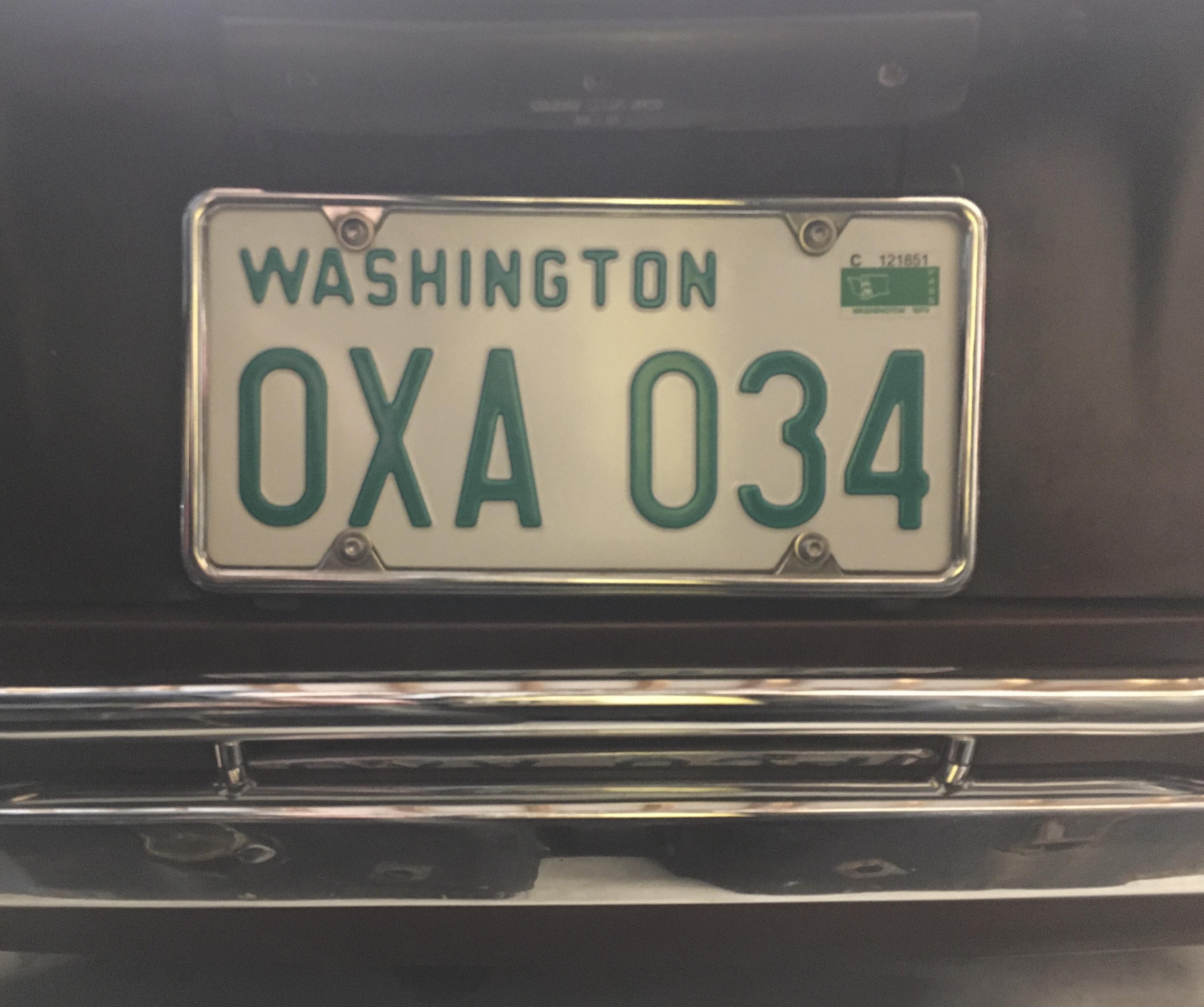
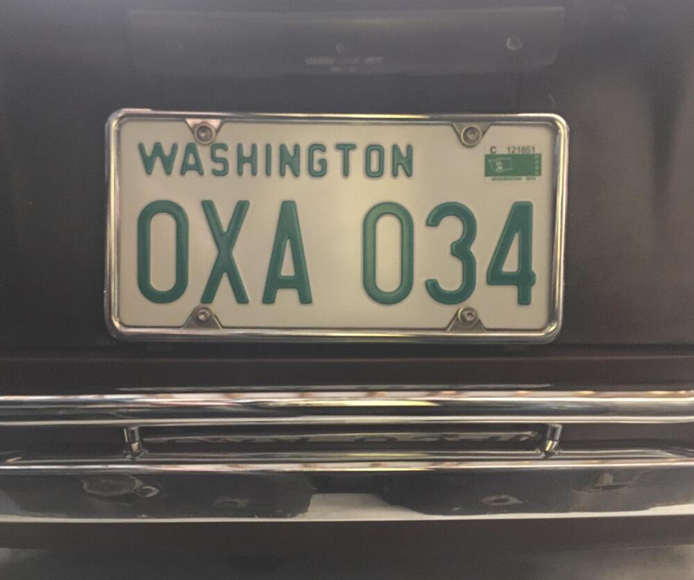
2 pointsCalifornia is unique with YOM plate registration. 1969 is currently the last year a passenger vehicle can be registered with YOM plates. In Washington state the laws are a bit less restrictive. I have registered my 72 Z with a YOM plate. Only one plate is required, and the registration never expires. The law does limit the use of the car to driving to and from shows and club functions, for testing purposes, and (I like this one) for pleasure. To me, the last line gives me the ability to drive the car all I choose, as every time I drive it, I do so for my pleasure. My YOM plate:
 2 points
 -
Glad you’re better Cliff. The library was getting out of sorts with you gone. Sent from my iPhone using Tapatalk2 points
-
Magnets are important! I have some fender pads but without magnets they won't stay in place. I have asked for someone to put magnets on them for Christmas for two years now but no luck...2 points
-
2 pointsMy only employee. He has one task, catch bugs. Looks like he will be filing a workman’s comp case. Sent from my iPhone using Tapatalk2 points
-
2 points
-
2 pointsI worked on the engine compartment yesterday. It’s cleaning up nice. Sent from my iPhone using Tapatalk2 points
-
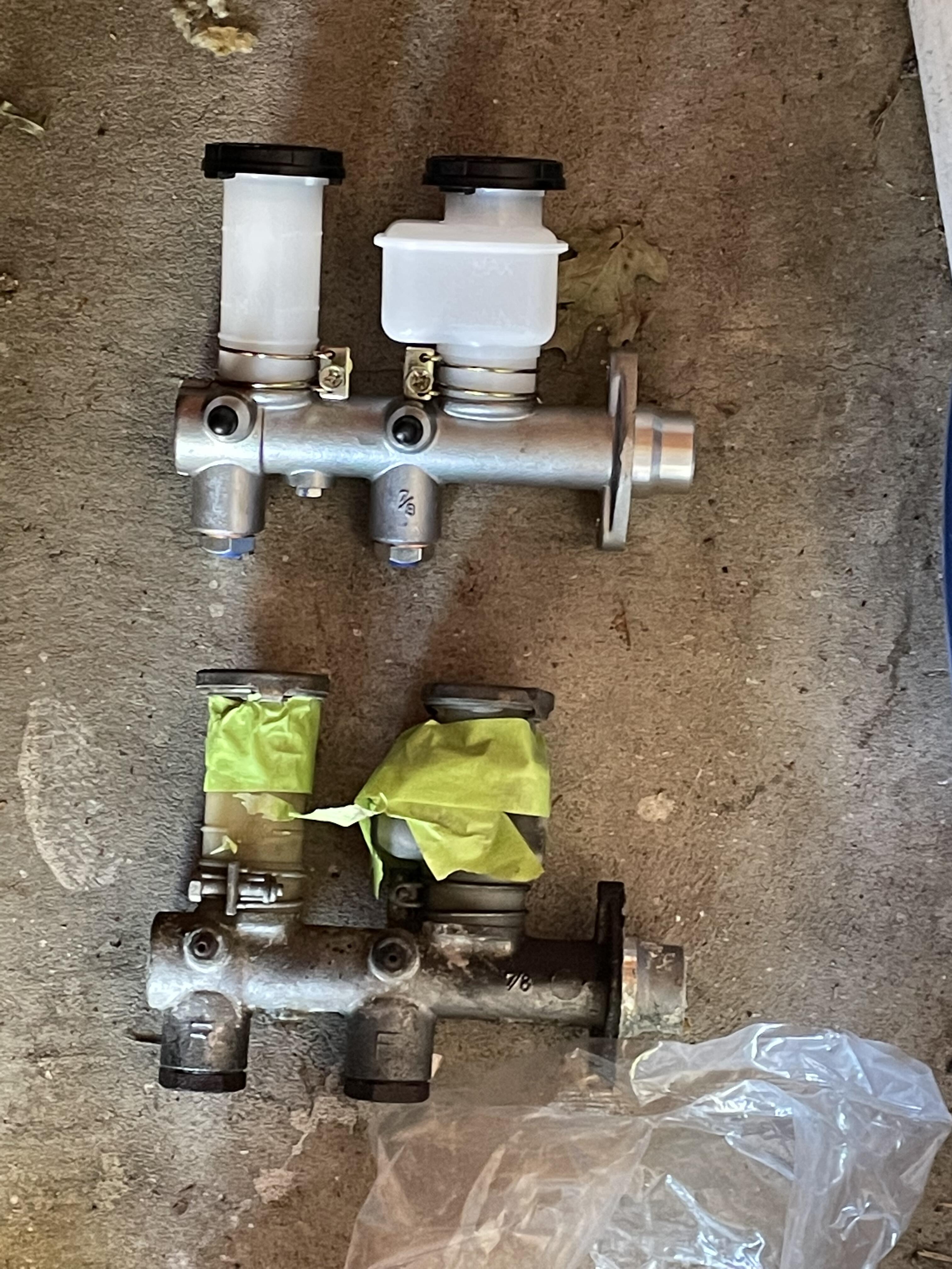
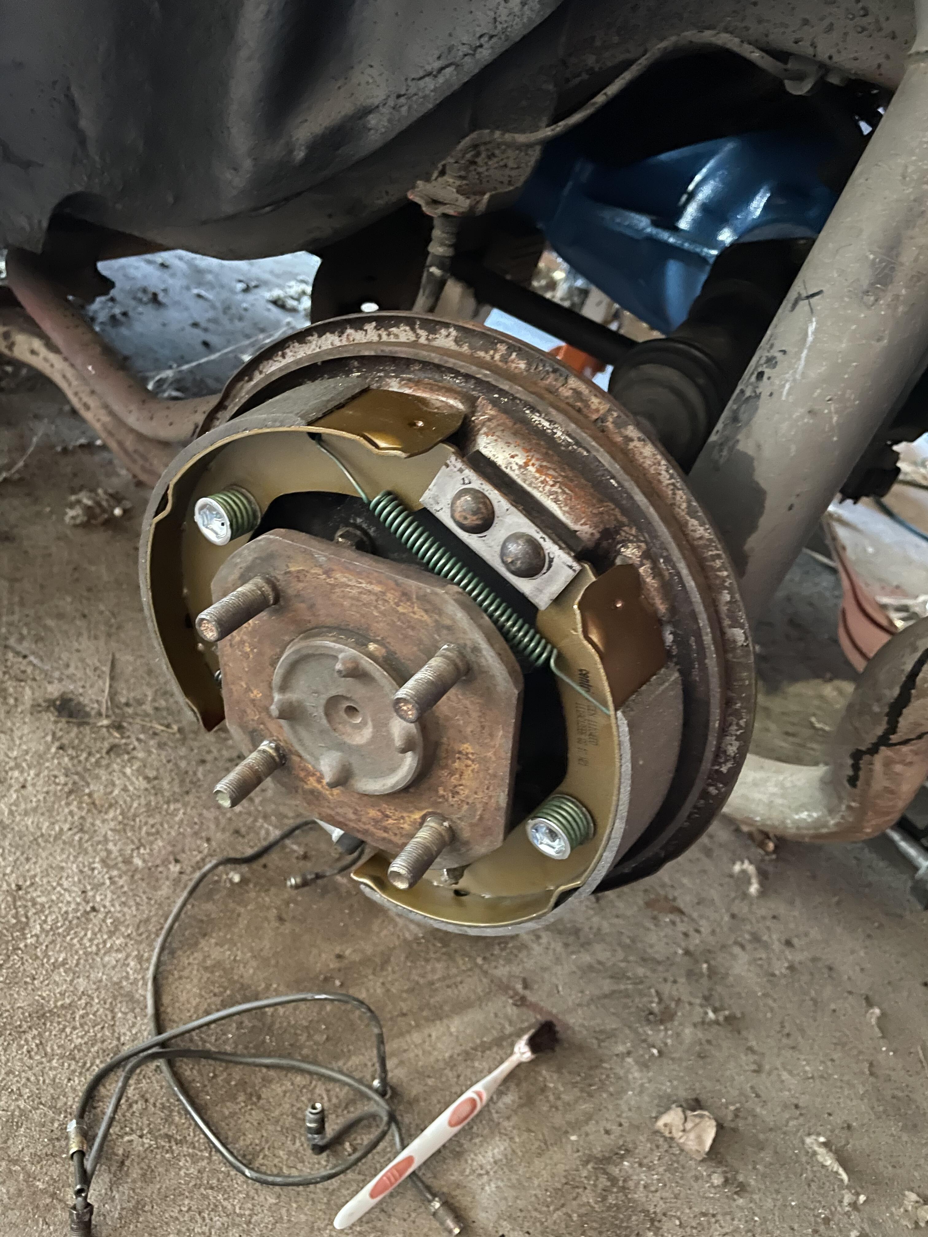
1 pointNew brake master cylinder has been installed and drums have been rebuilt. Going to get the brake covers turned.


 1 point
 -
The last part of the diagram that shows the common relays is correct except I would call the yellow wire "starter solenoid" instead of "emergency switch" You can also buy connectors from Vintage Connections to match up to the connectors in the wiring harness.
 1 point
 -
I use regular fender covers, and gaffer’s tape to hold them from slipping. I found the type with magnets would get bits of metal on them, and it would scratch the finish. I also try to avoid leaning on the fenders, as they dent quite easily.1 point
-
I just hover above my car using my extreme mental powers1 point
-
1 pointThey extended YOM program to 1980 and older cars, but it’s odd the DMV website doesn’t mention that except on the application form. I’ll do some more homework. https://www.dmv.ca.gov/portal/file/year-of-manufacturer-yom-license-plate-application-reg-352-pdf/ Sent from my iPhone using Tapatalk1 point
-
1 point
-
1 pointFrom what you say I'm guessing it's the rear brakes. I you decide it's the wheel cylinders and you want to replace them you can use the newer cylinders with some minor brake line tweaking on the back of the drums. Here's a thread I did when I replaced mine.1 point
-
1 pointCould be corrosion in the cable not letting it fully release. Not sure how the set up is on earlier Z’s though Sent from my iPhone using Tapatalk1 point
-
Happy to hear your OK Cliff, Do you know if it was the omicron variant? or delta? If you did'nt loose taste i believe you had the omicron.. Btw.. ON topic.. @Mike I don't complain about the slow site, i'm here on a free ride and glad that i can do this for free! (i'm sitting home now for almost 22 years.. can't do much anymore so i'm glad to communicate with you guys about the hobby.) But i have not seen a reaction on here from you Mike since Zedhead started this topic.. Is there nothing you can do about it? Just asking.. i just clicked a topic and it just did'nt load ever.. then this topic and it loaded on the spot.. this is weird to say the least.. is'nt it? Hey Cliff.. i can imagine how happy you were when you could go to work! I wish i could to but i'm "o3" forever...... (Yeah i wanted to use a abriv.. 😉 )1 point
-
1 pointUsing the emergency brakes shouldn't make them drag. Brake shoes not returning could do it or brake cylinders corroded and not returning could do it... Those are my first thoughts1 point
-
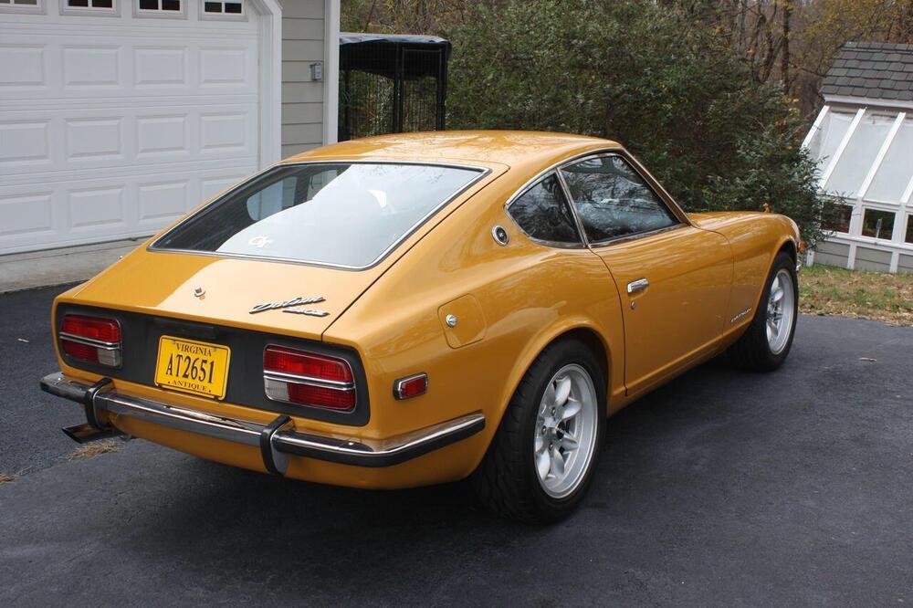
1 point52 years of sun damage. Gold standard seats. Sent from my iPhone using Tapatalk1 point
-
1 pointPerfect dash and an AM radio. The electric antenna is original and works fine. Sent from my iPhone using Tapatalk1 point
-
1 pointLike new tools. Lug wrench and jack handle were still in the plastic. The plastic was opened but still intact Sent from my iPhone using Tapatalk1 point
-
You could go extreme and get a top side creeper. Sent from my iPhone using Tapatalk1 point
-
1 point
-
1 pointYep……From the quick glance I got, she’s quite the find….a real time capsule! I think Jim will agree a great color too. Glad you’re on the forum……If you need any help, we’ll get answers for you……we are all “Legends in our own Minds!” Congrats1 point
-
1 pointThank you. Hey, If people keep commenting, I don't really have a reason to not comment. I'm the kind of guy that makes noise. When I worked for the government and they were overspending, I would bring it up. They told me it was none of my business. I was a tax payer so I saw it as my business.1 point
-
1 pointI don’t think he was suggesting blocking you, but rather pointing out that blocking another member is an option for any member who finds another member bothersome. At this point it might be a good idea to simply move on to other discussions, and let this thread take a rest.1 point
-
1 pointCharles was a gentleman. He expressed his disappointment, he didn't take it personally. DatsunZguy was the one to explain to me that posting pictures was boasting. I've never seen myself as one that would boast, so I deleted my photos. Also, I sent a pm to Charles letting him know what I paid. Honestly, I was always taught to never ask people the price of anything. If the buyer want's you to know, they will let you. I've been told at times to quit boasting for providing the price.1 point
-
1 pointI also thought the "no" response was a little on the negative side and really doesn't have anything to do with you being proud of your find. My guess is that Patcon also thought you had a nice find and was just curious on the range of the price for such a nice find (that us late comers have no idea on without pictures). Charles (patcon) is one of the more helpful/supportive people on these boards and other than you I doubt there's anybody else on these boards that saw his question as overly prying. I know when I was growing up and I got a just "no" (or "maybe" which always meant "no") from my parents it was viewed as a negative response. This whole thing reminds me of the kid that didn't get what he wanted so he took his ball away.1 point
-
1 point
-
CO posted a time stamp version. The tarp is at the beginning. Before "working on a sex farm, plowing through your bean field".1 point
-
Just be sure to wear your tin foil hat when you Google the terms and you'll be fine. 😎1 point
-
If you submitted a credit card number with that order, I would monitor it carefully. I have NEVER had to submit extra documentation to a vendor and to hell if I ever would. Pay a few bucks more and buy from a reputable vendor like Motorsport Auto or ZCarDepot.1 point
-
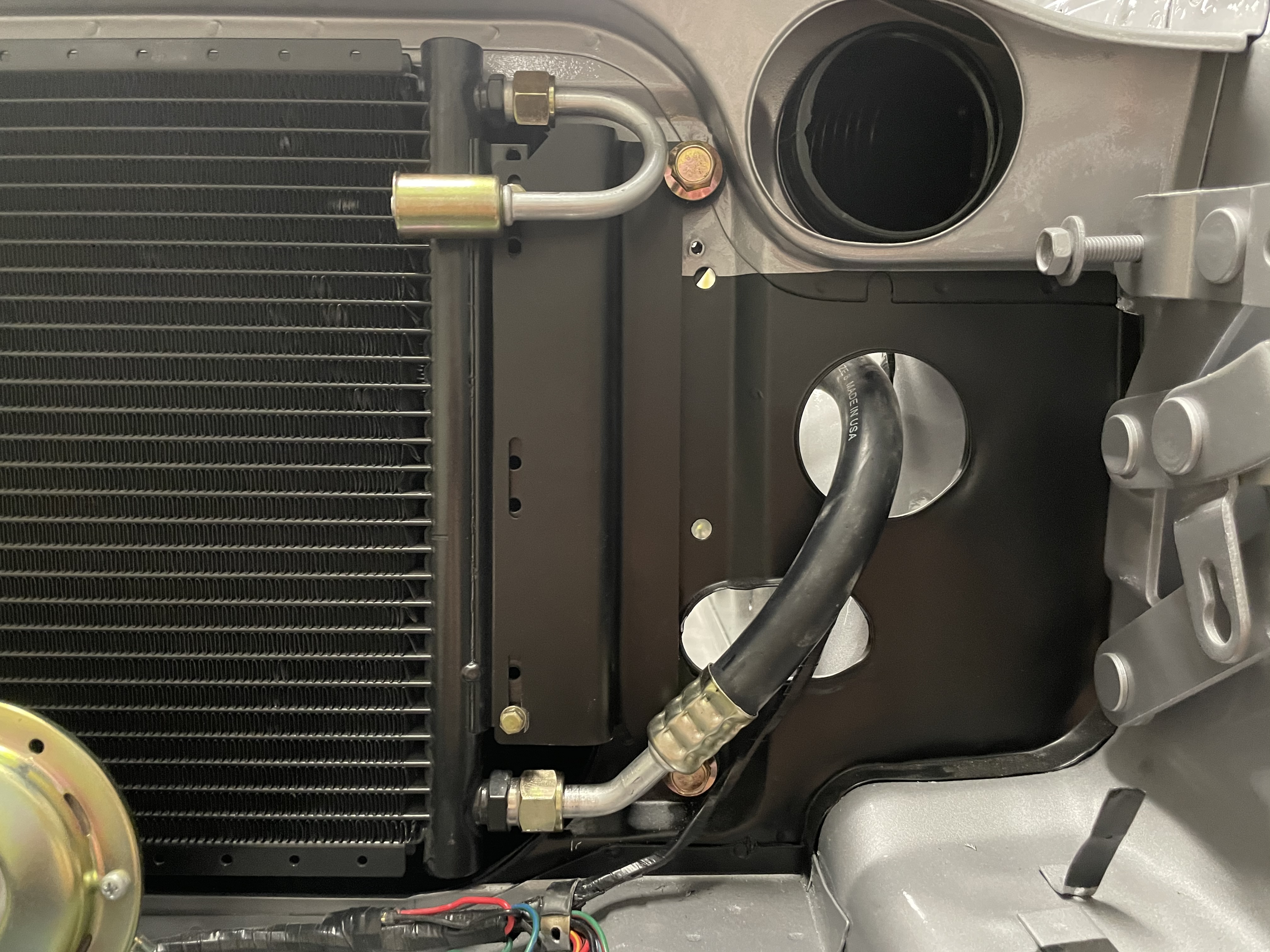
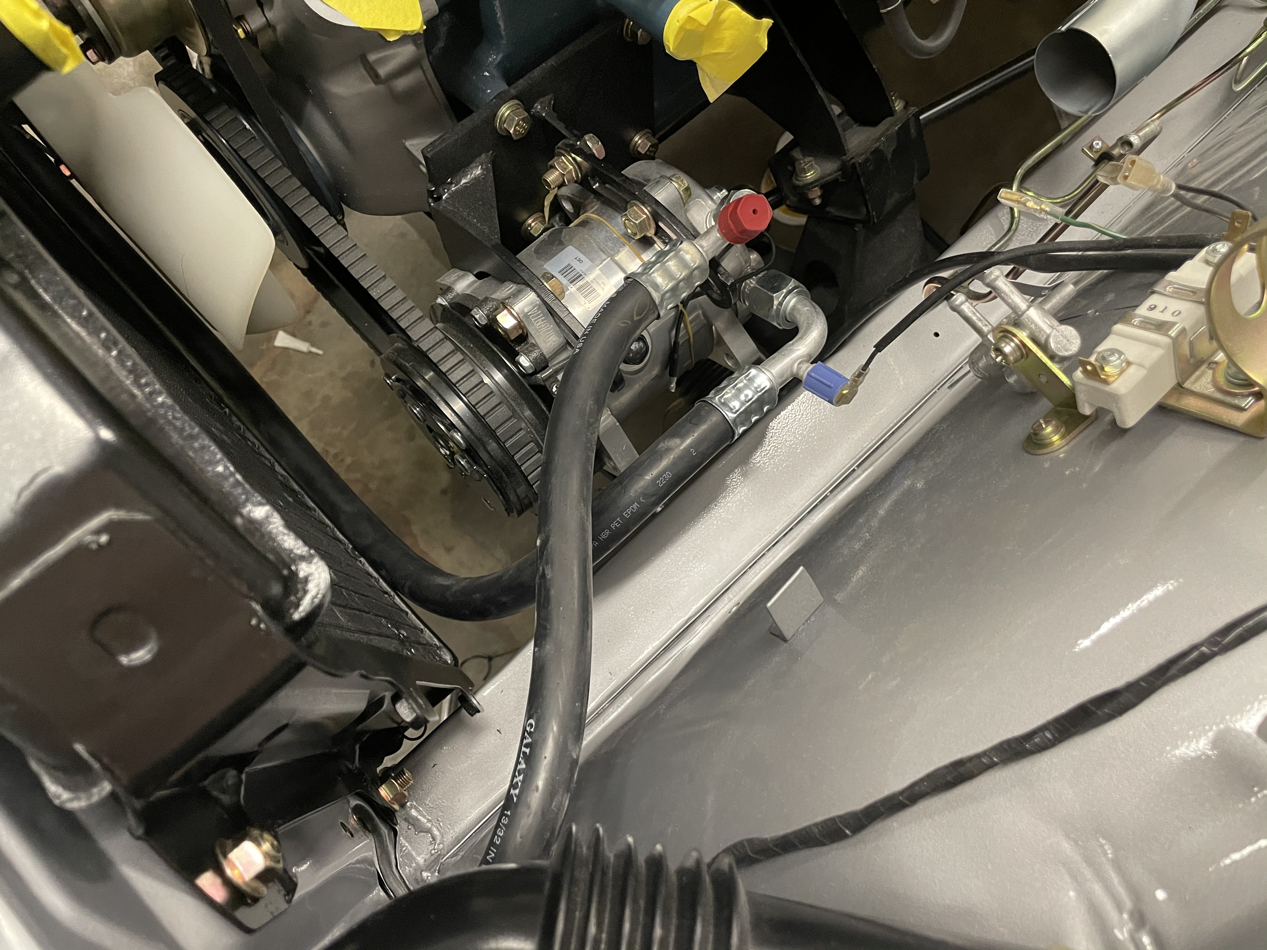
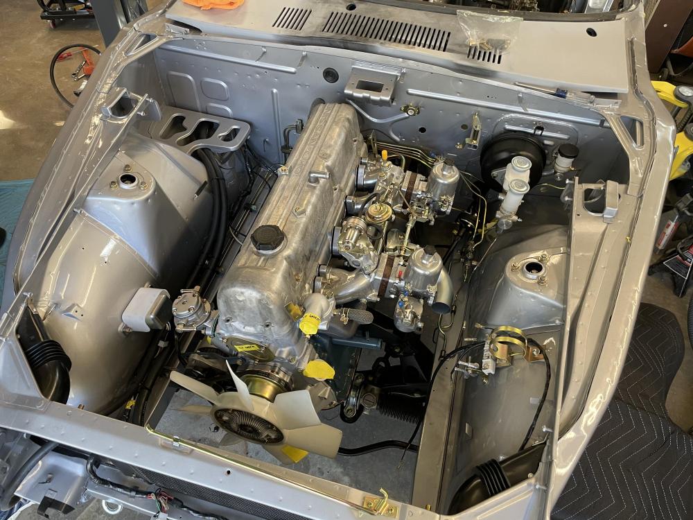
1 pointSteady progress has been made to get everything ready for the first fire up. While we wait for a few parts to ship in, I worked to get the AC system finished up, and cleaned up the valve cover. So far the AC system is routing like I had hoped, clean and out of the way. I never liked how the dealers installed the drier on the inner fender with sheet metal screws. On the front core support it should hide nicely from view.
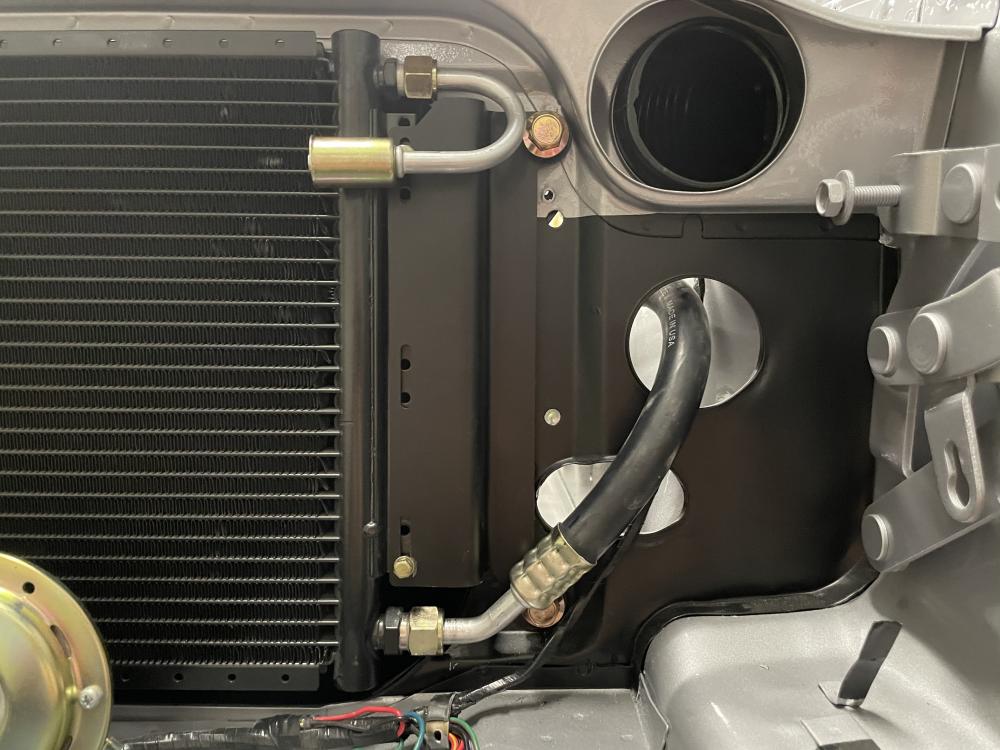
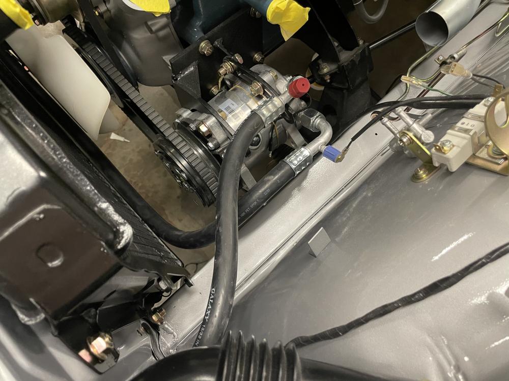
 1 point
 -
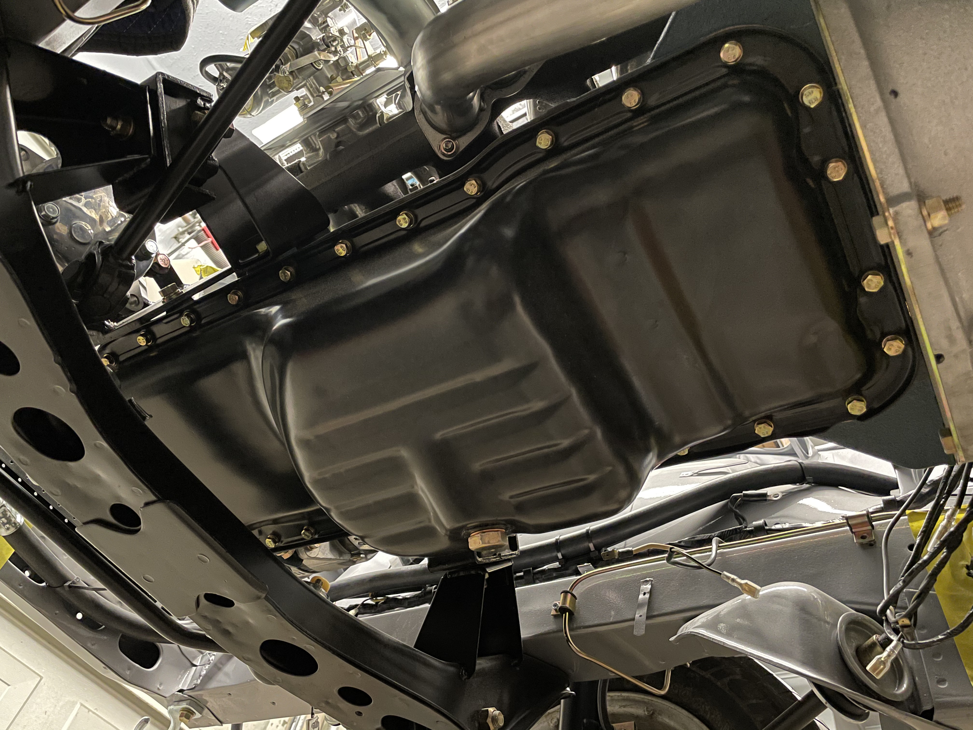
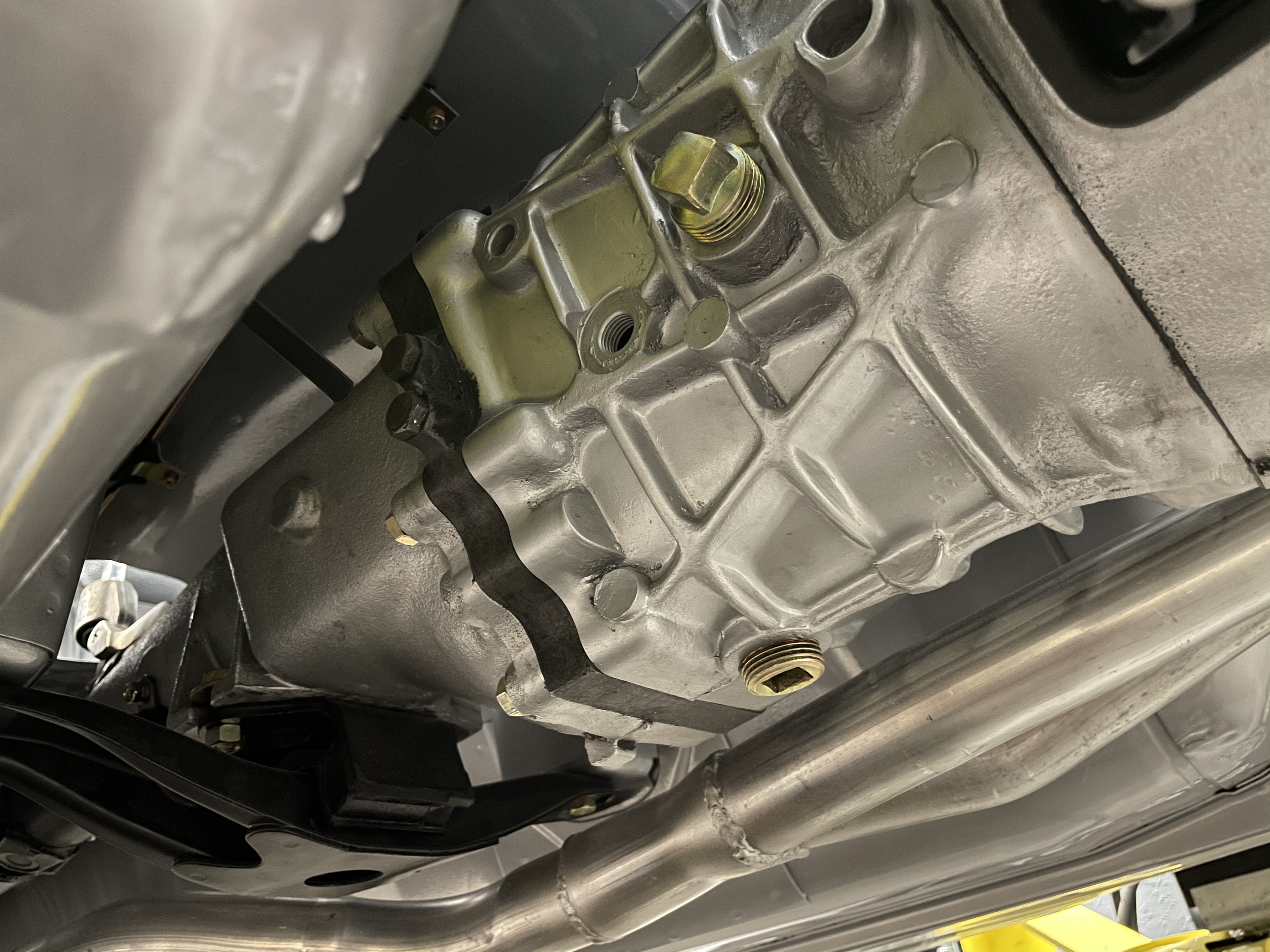
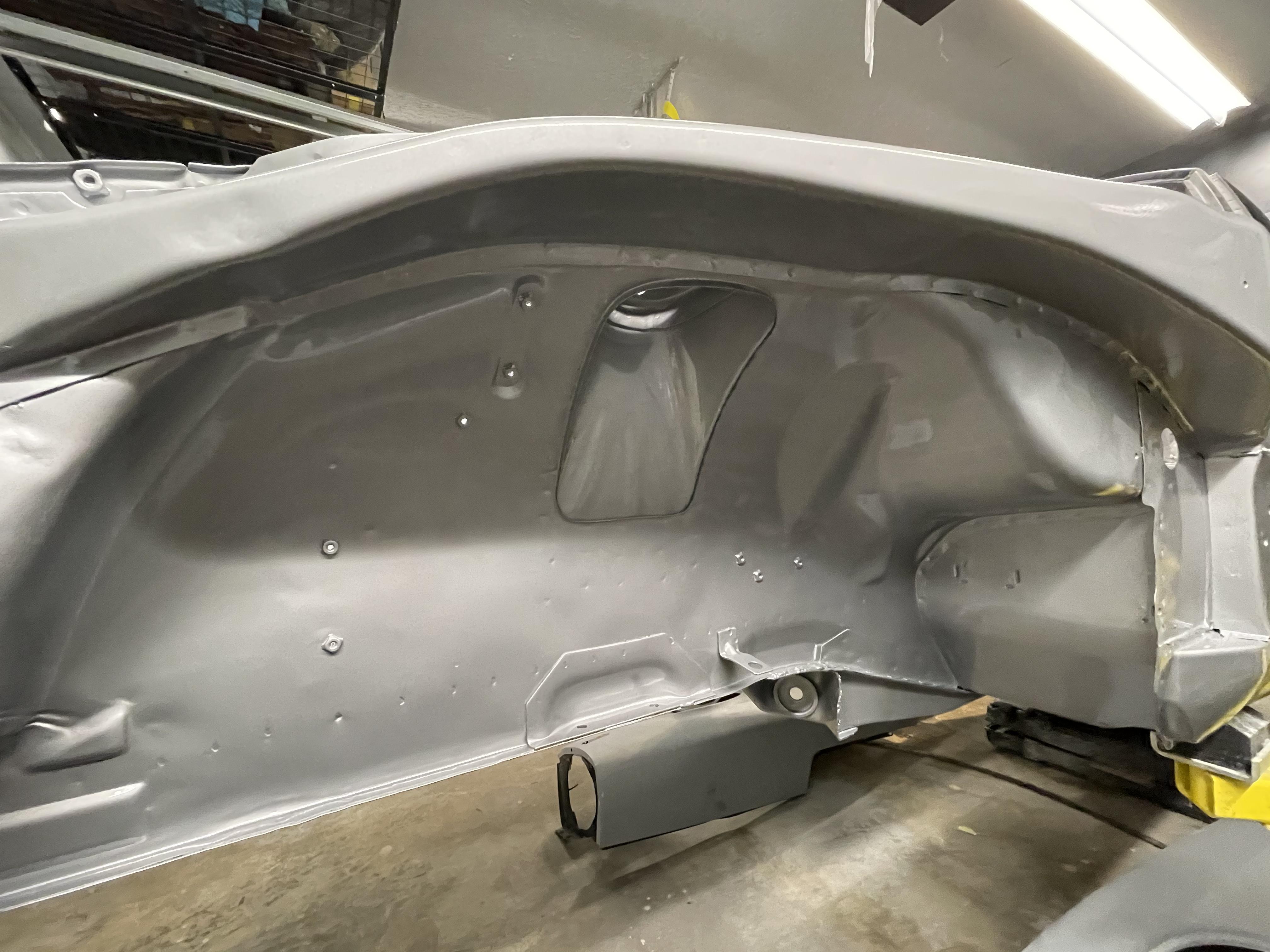
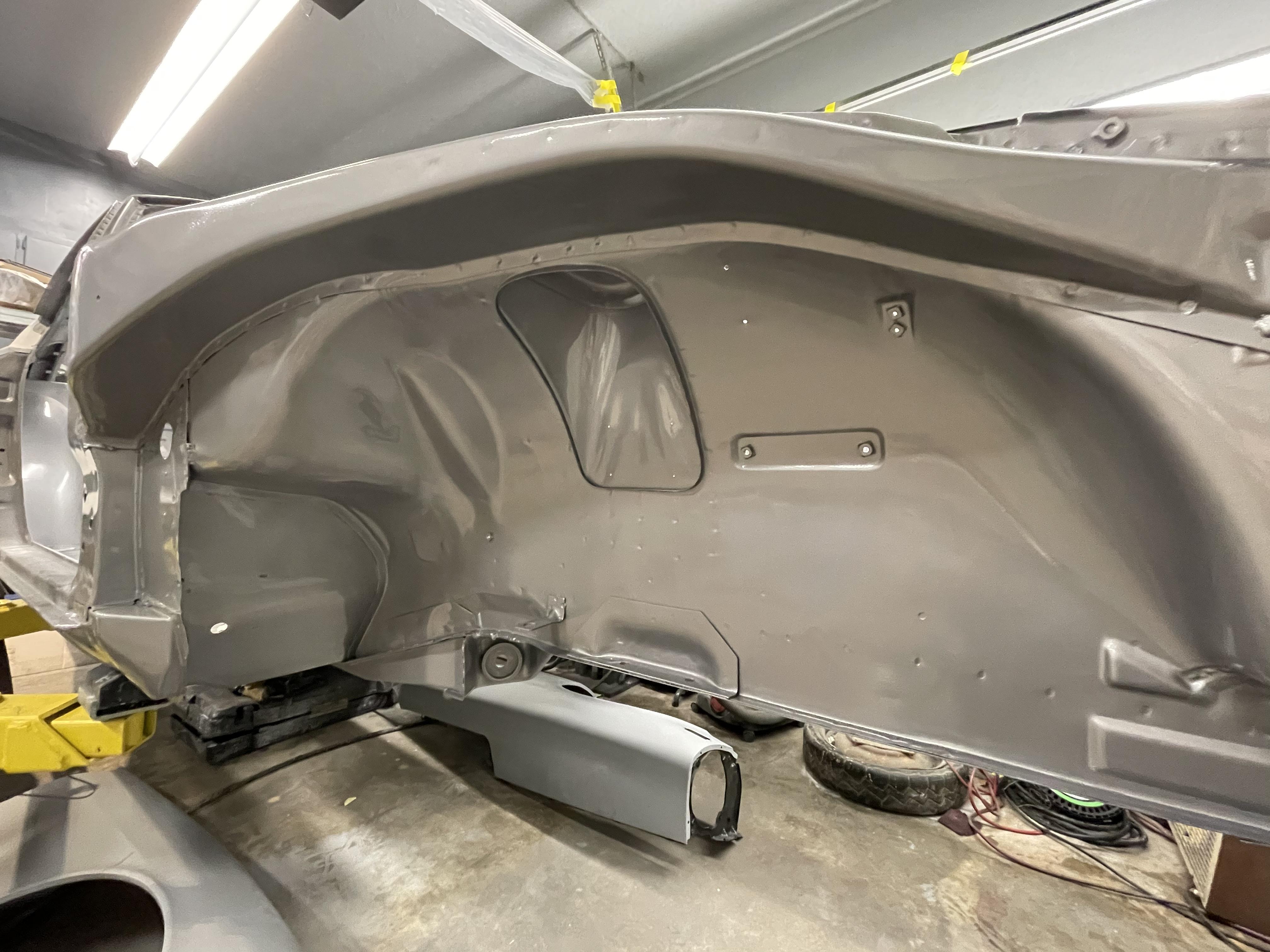
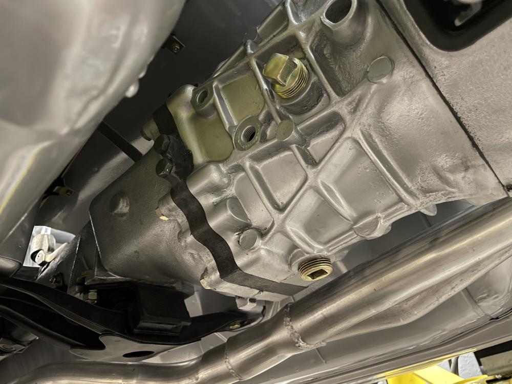
1 pointLot of body work has been wrapped up on the body of the Z in prep for final paint. Not very exciting to photograph, but the drivetrain it just about buttoned up.
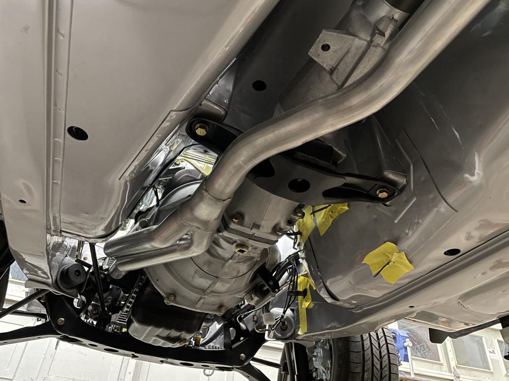

 1 point
 -
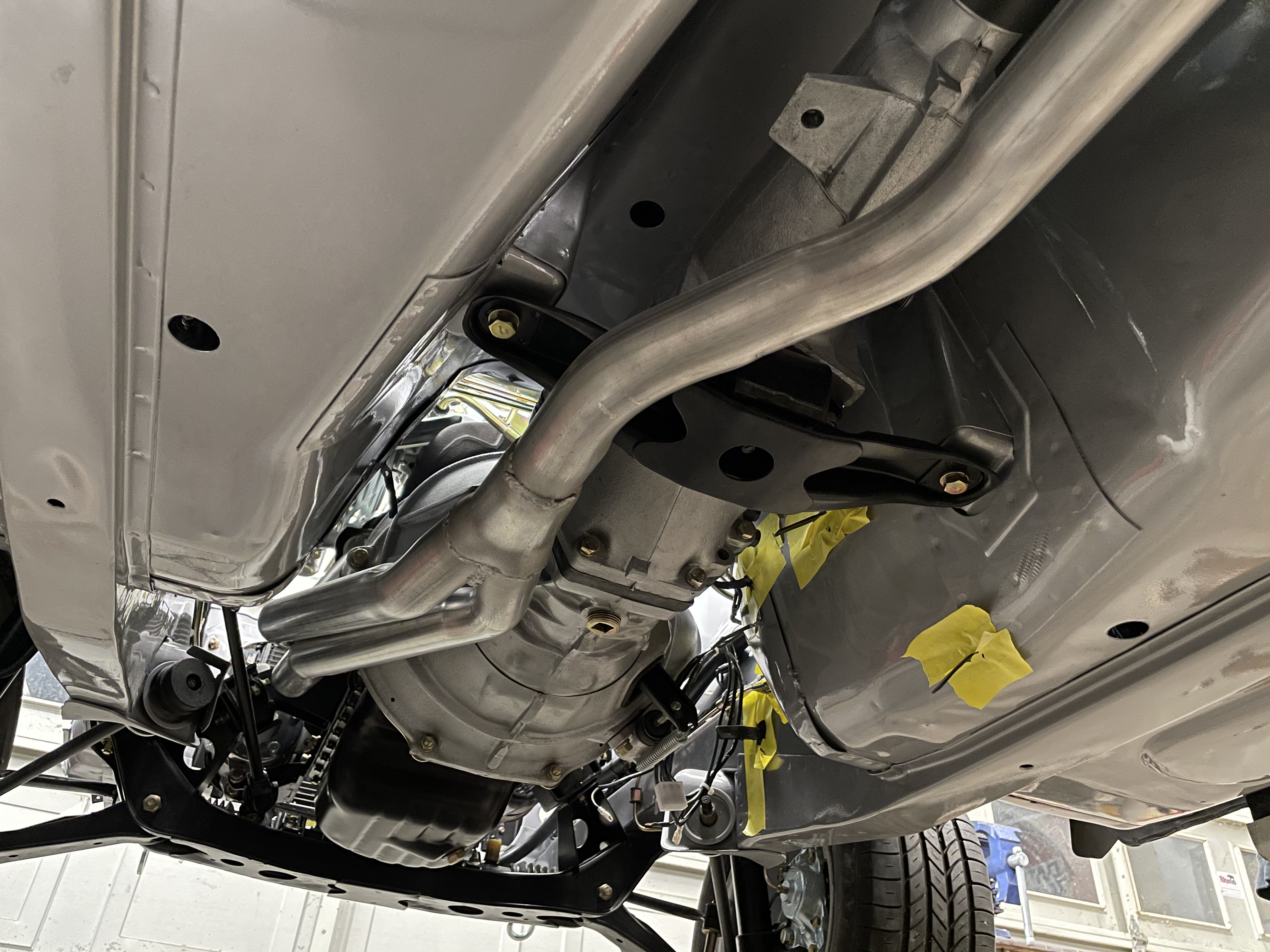
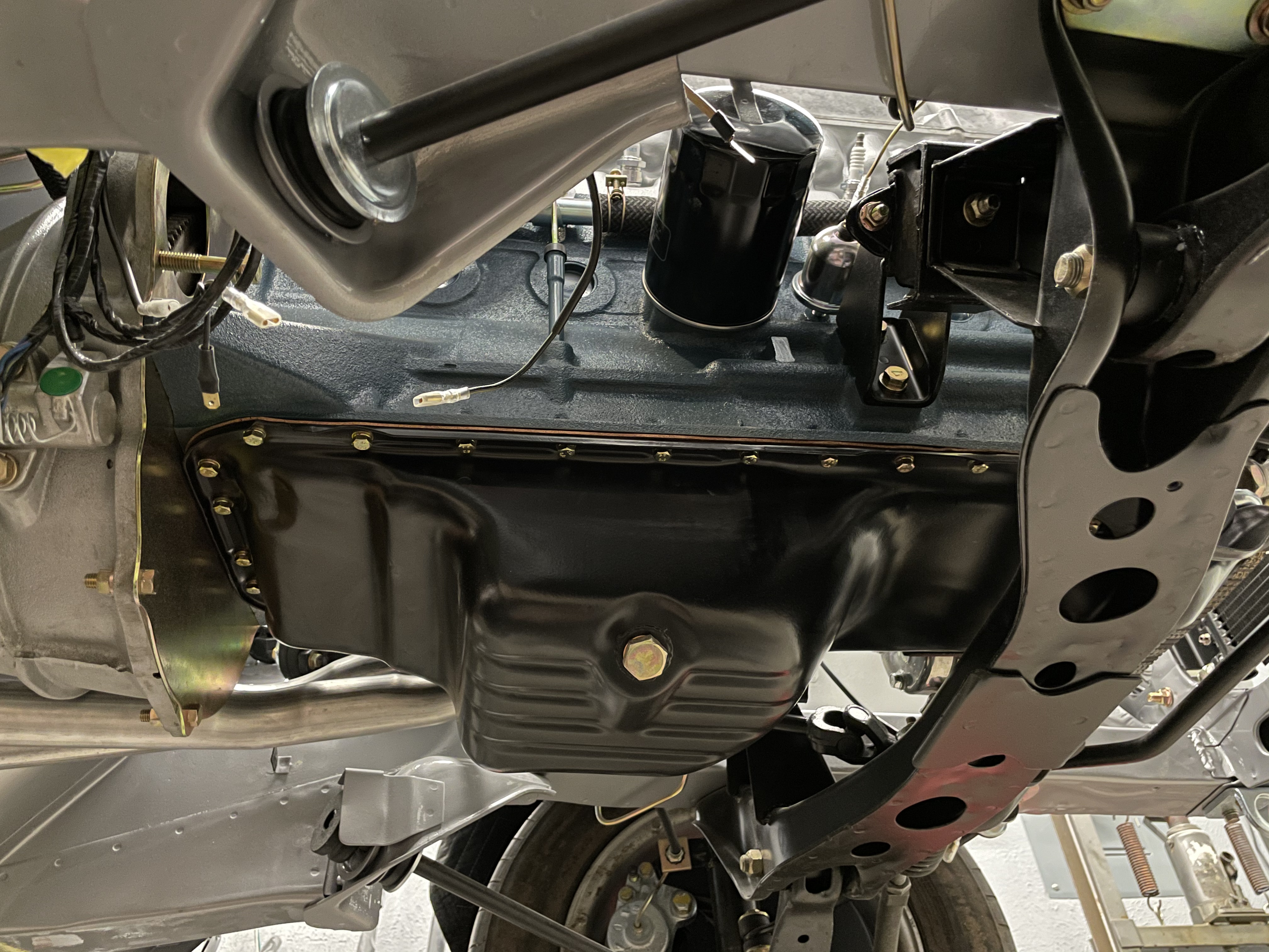
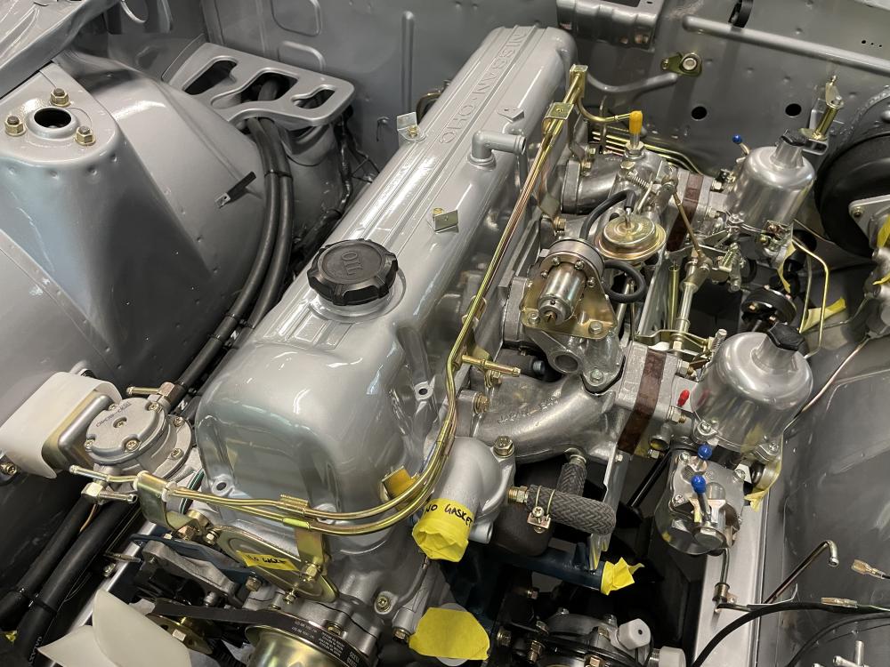
1 pointQuick shot of the drivetrain install that was completed over the weekend. Now that there’s no worry about scratching the valve cover, I’ll pull it and finish cleaning it up. Z Therapy carbs mocked up and looking good!
 1 point
 -
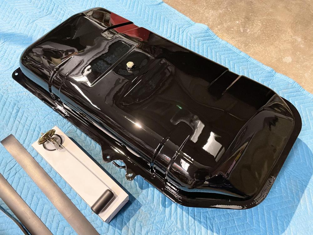
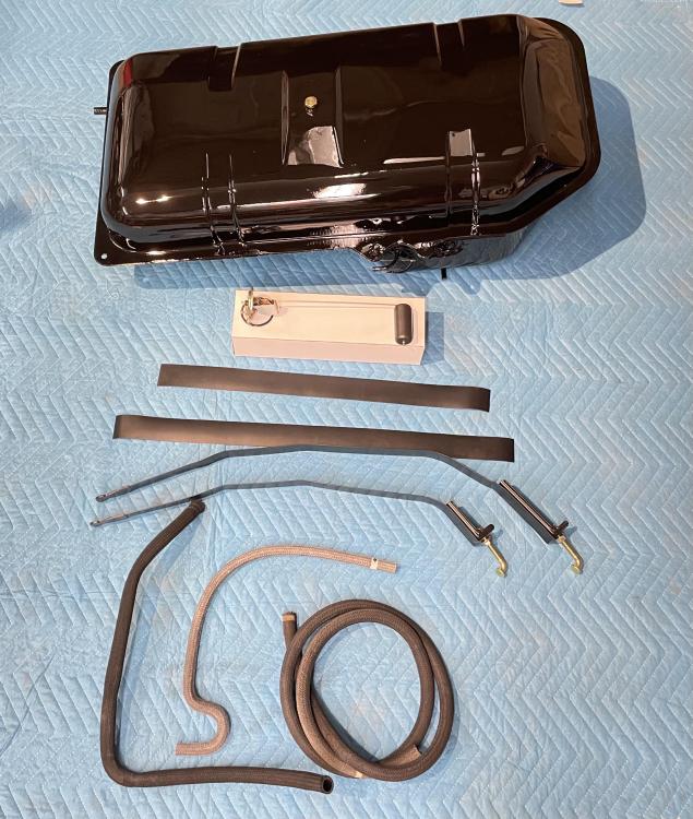
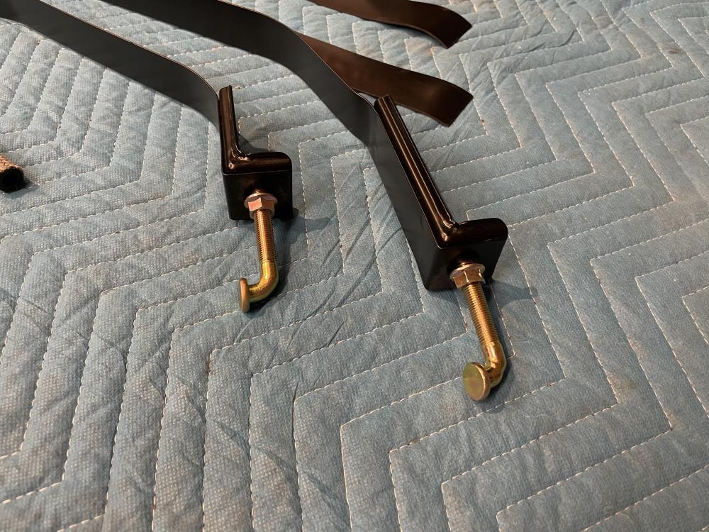
1 pointLot of not so glamours work has been done on the Z lately. One task just about complete some might appreciate, restoring the fuel tank. Tank was boiled out and sealed, followed by many hours of body work to get the underside as smooth as possible. Finished out with a new sending unit, powder coated straps, new rubber liners, hoses, and replated hardware.
 1 point
 -
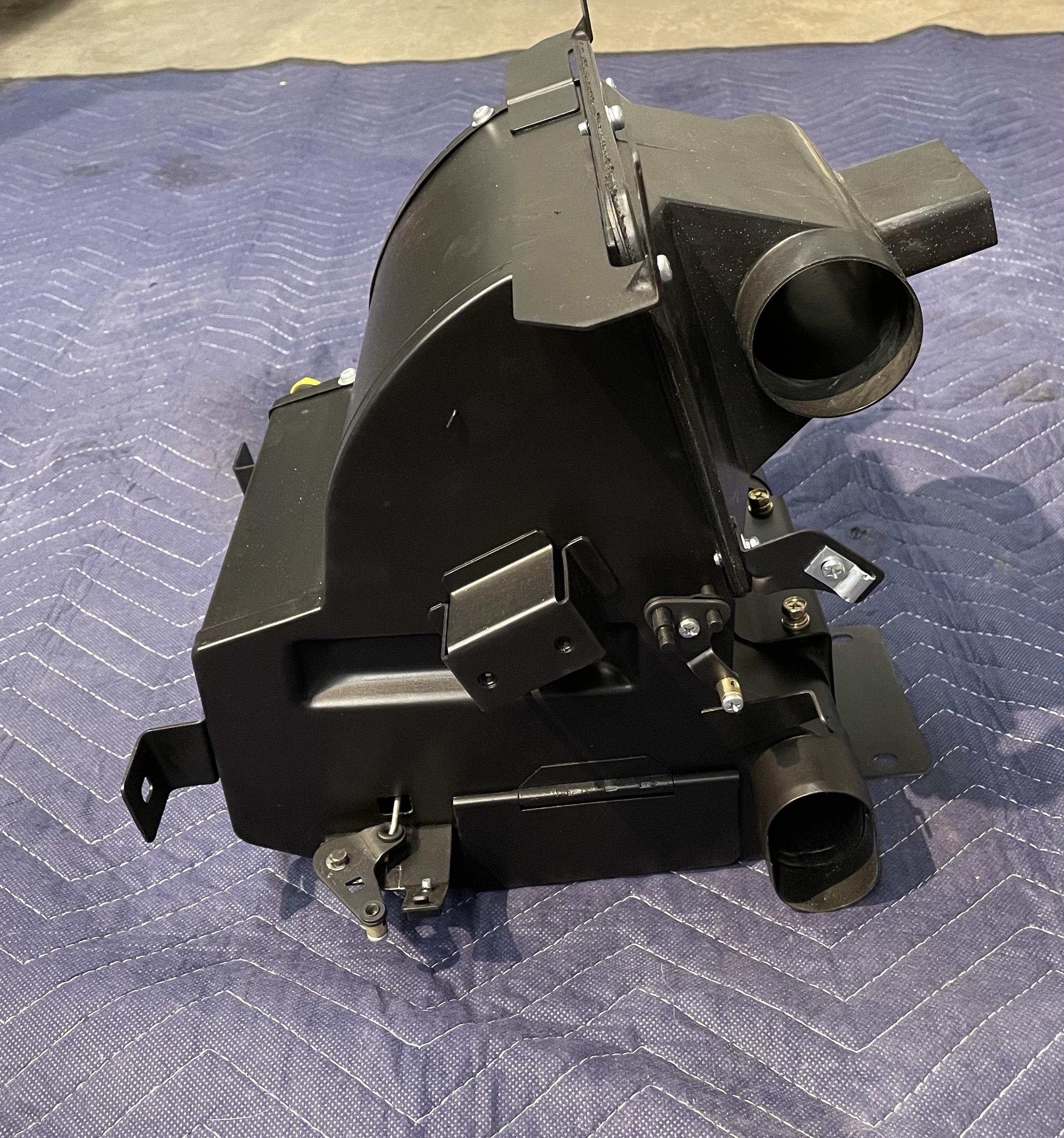
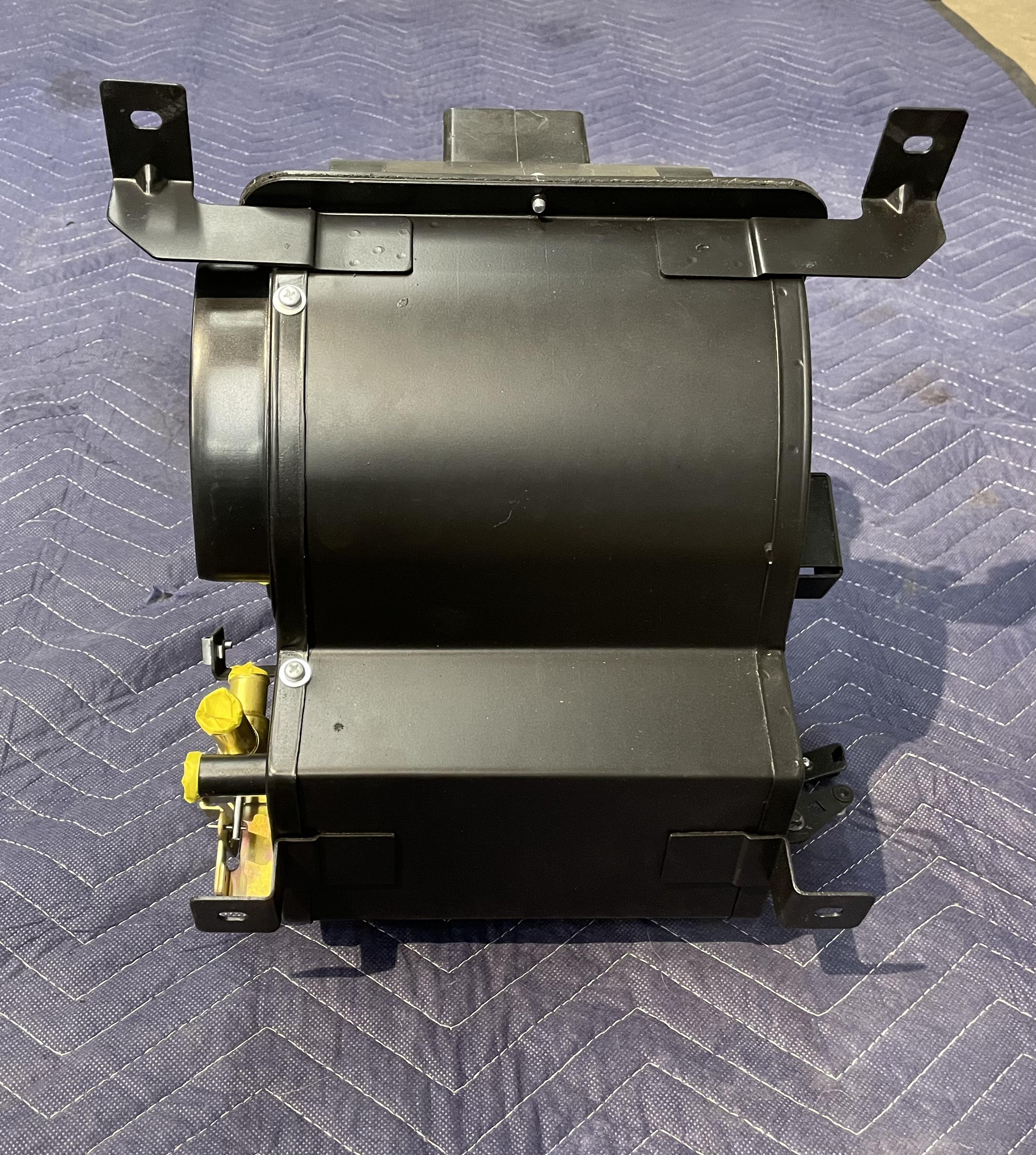
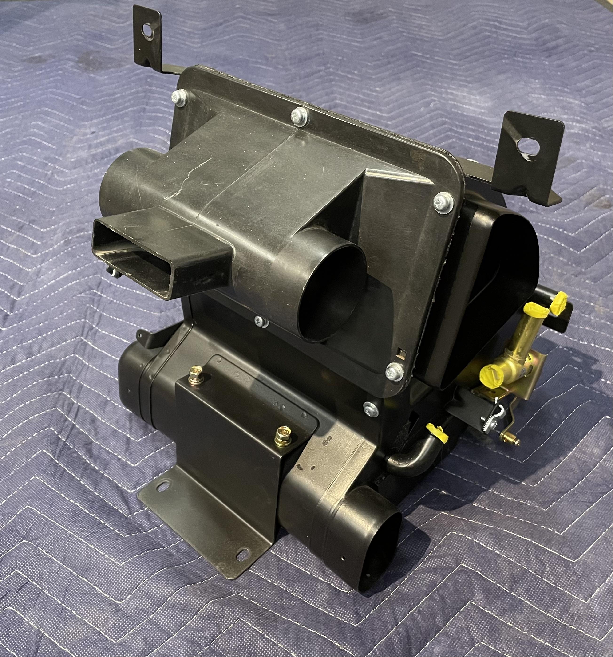
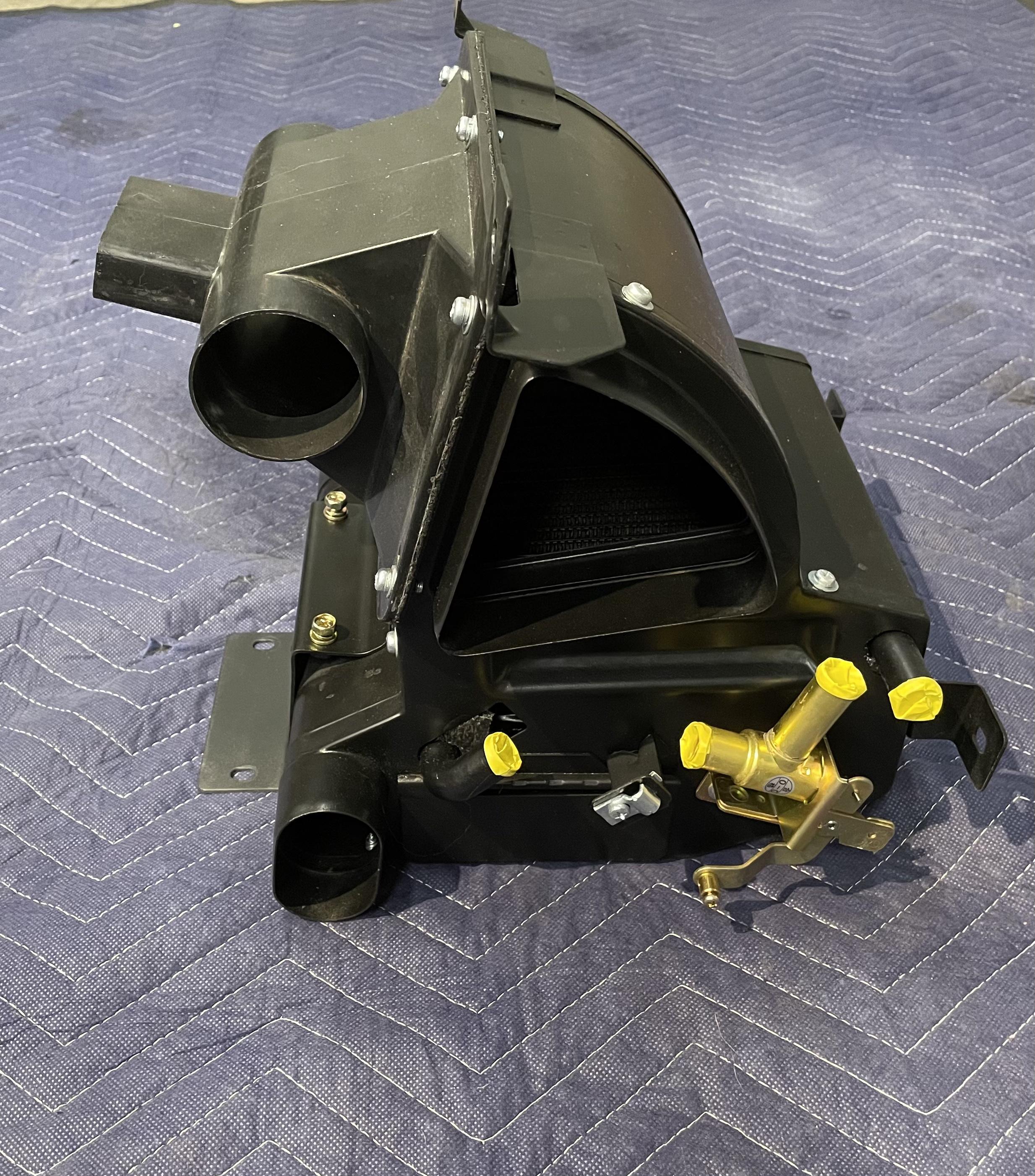
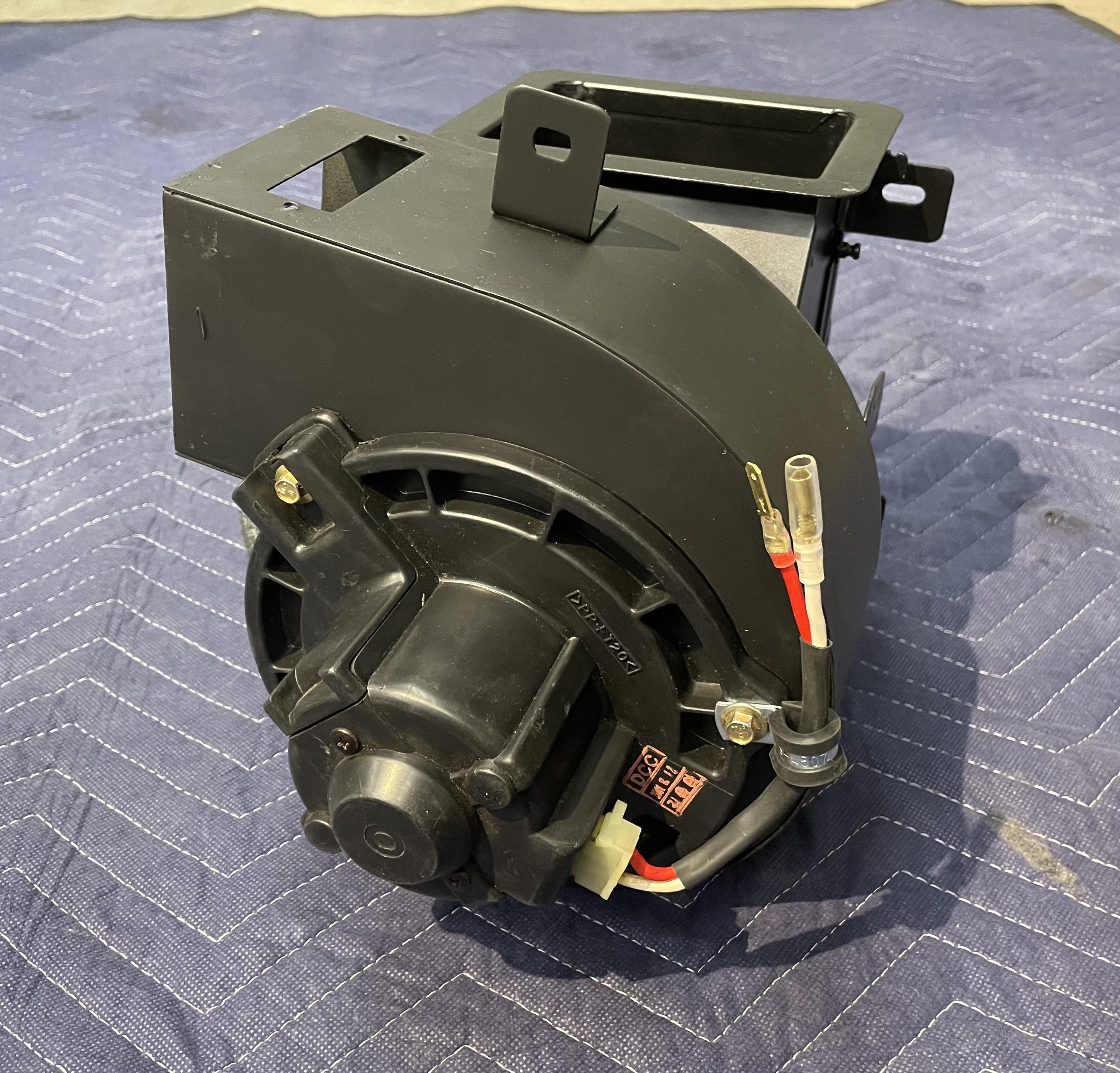
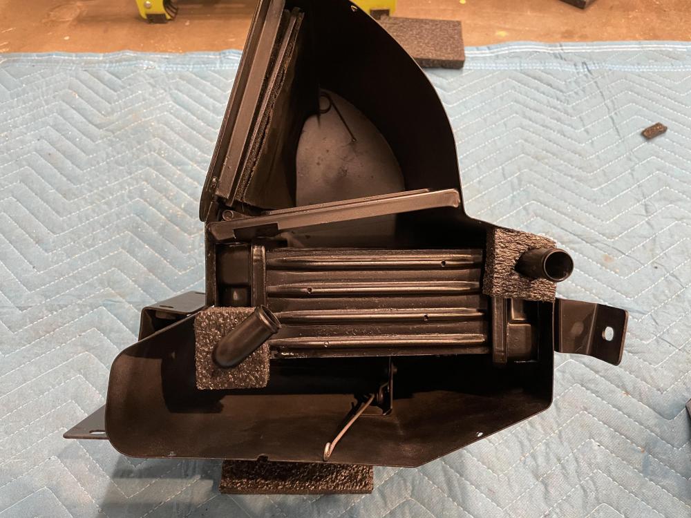
1 pointUpdate on the heater core. Unit has been reassembled and just about ready for install. Blower unit is lacking the heating element to complete the rebuild.

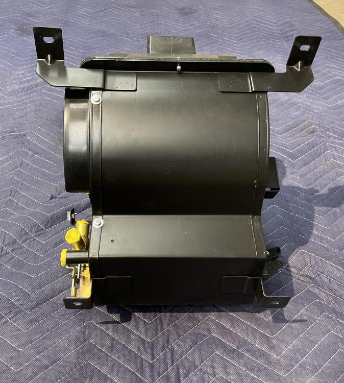


 1 point
 -
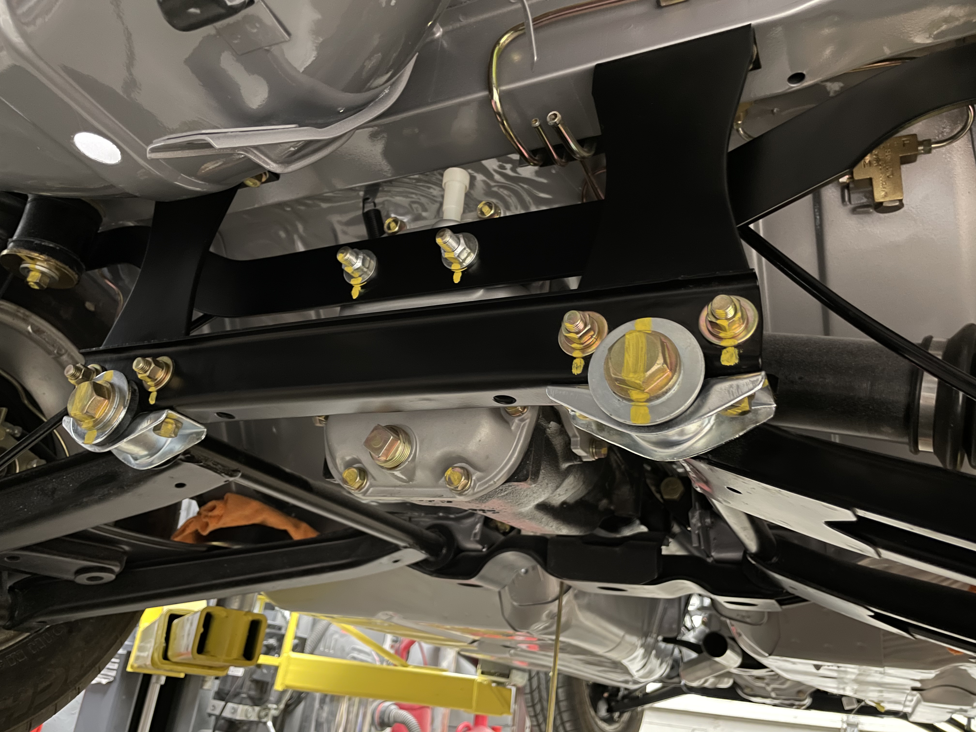
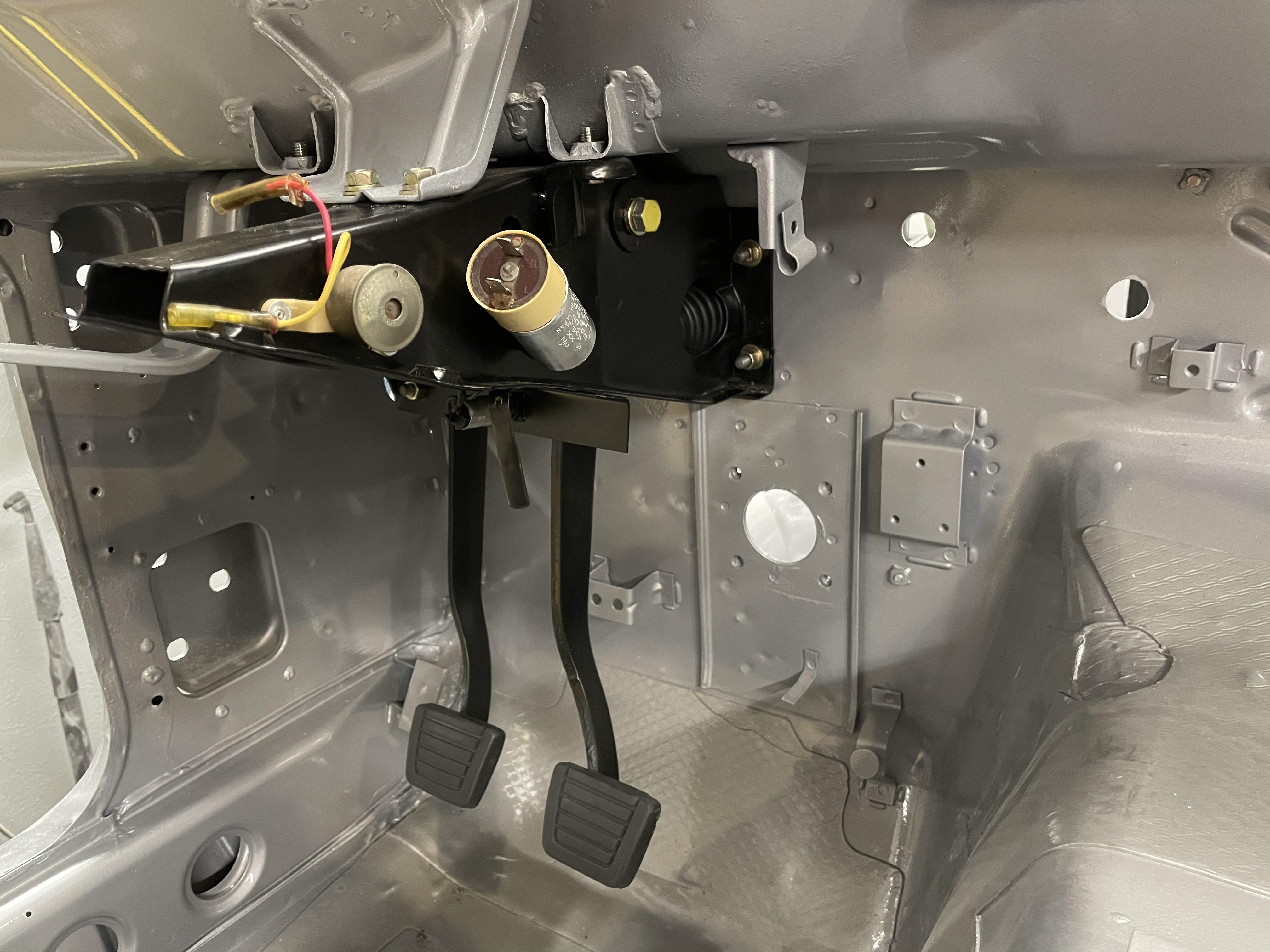
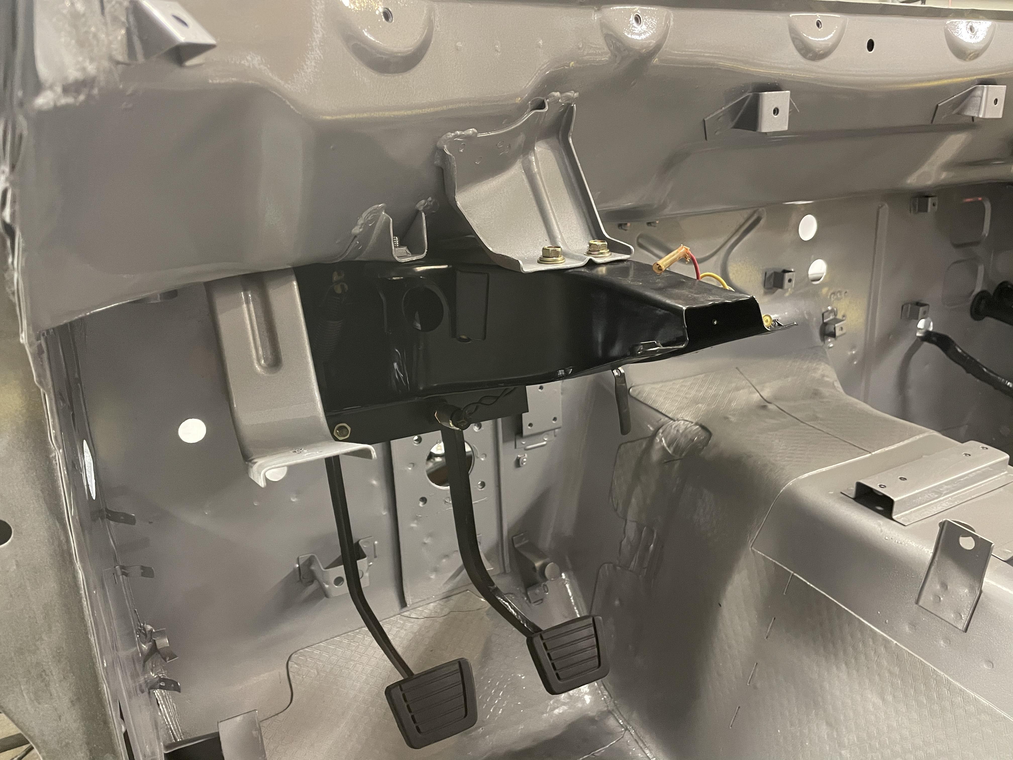
1 pointFew updates on the Z. Tonight’s progress includes mounting the rebuilt pedal box assembly, brake booster, master cylinders, and last of the hard lines.


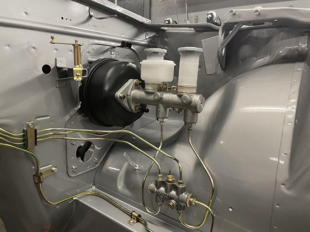 1 point
 -
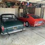
1 pointYep, the NA RB Z31 is my son Brandon’s car. I can’t wait to see your finished product. These Z cars are so cool......drive it on dry days....enjoy it. What I’ve found out is the perfect restos don’t bring the really big money anyway......the original cars do. But, I don’t restore these cars for the money, just hooked on the Marque. I expect you are too. Great restoration....nice color combo!!!1 point
-
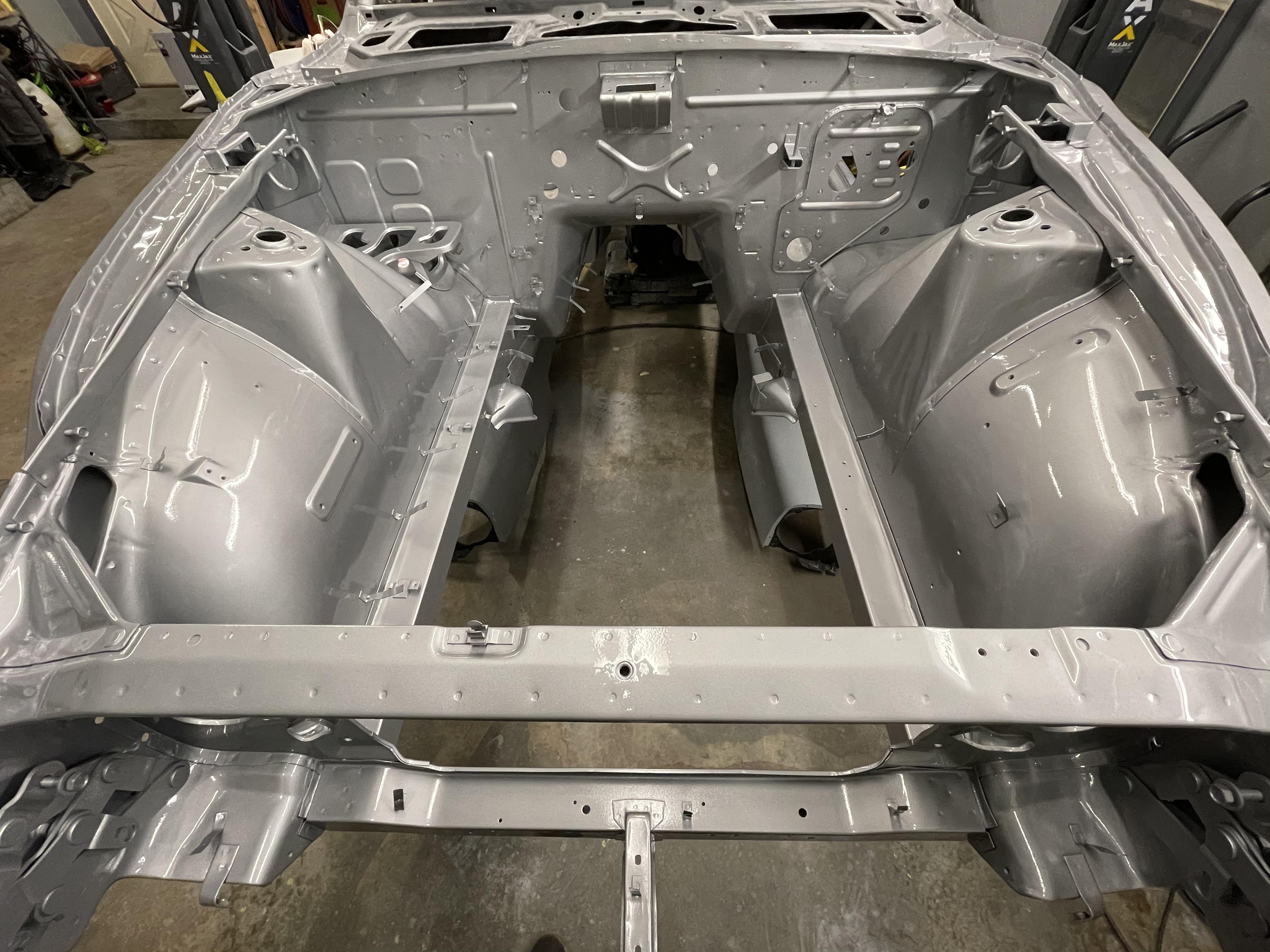
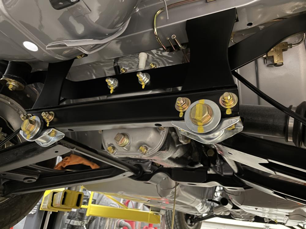
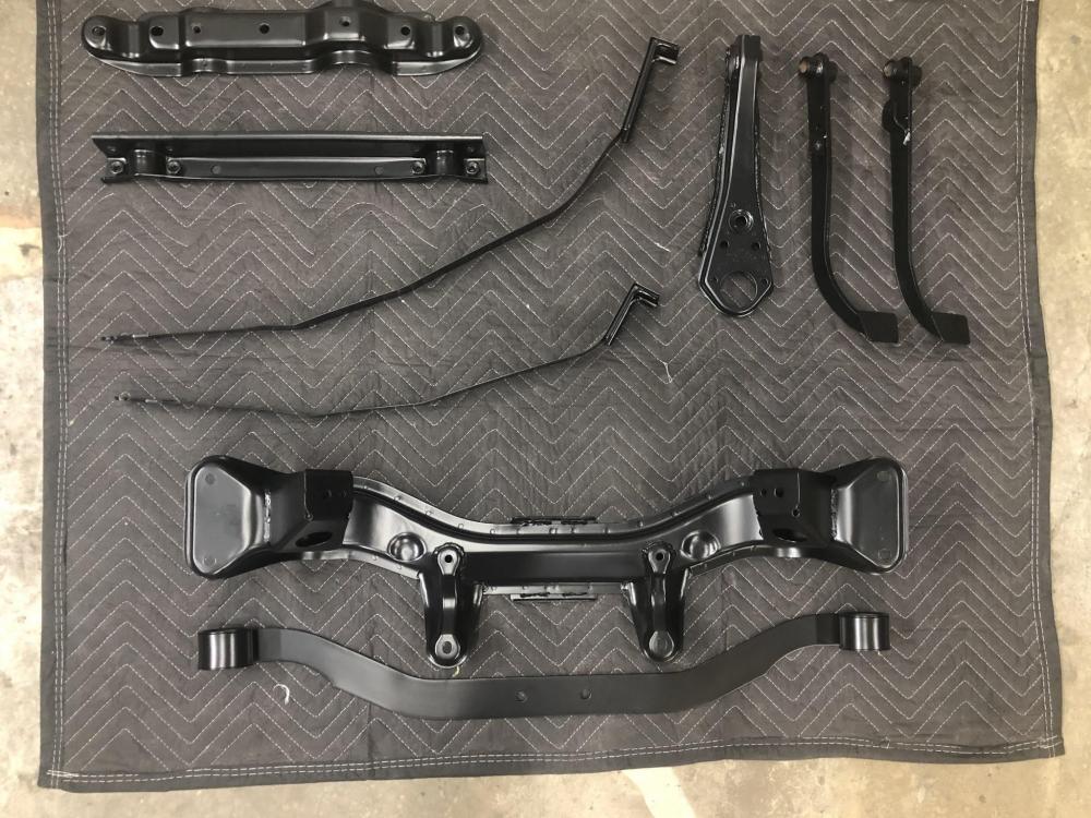
1 pointA ton of work has been done to the car since the last update. Many, many hours of prep work and paint to get the front clip painted this weekend. Now the reassembly can begin for the drivetrain and suspension.


 1 point
 -
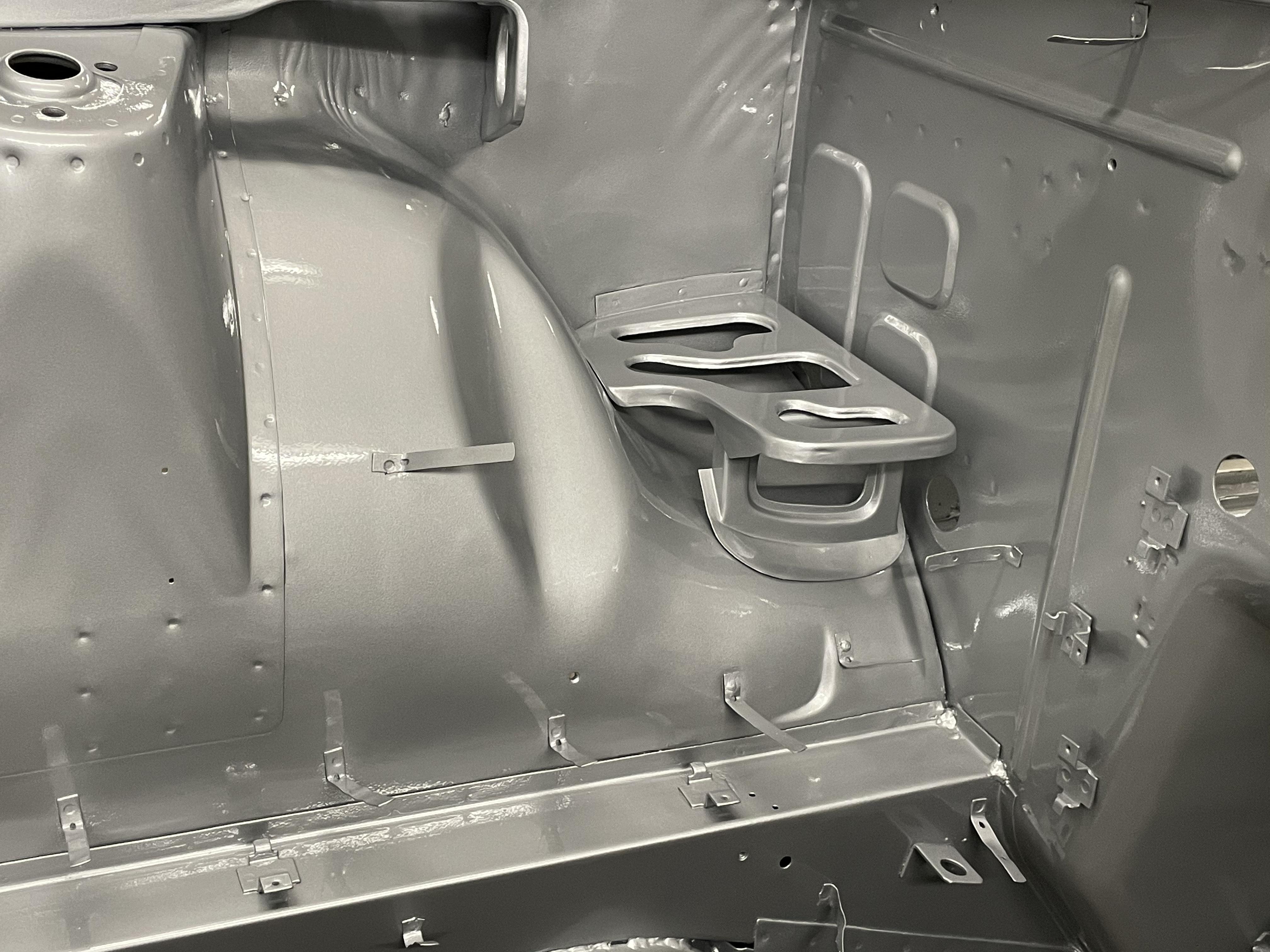
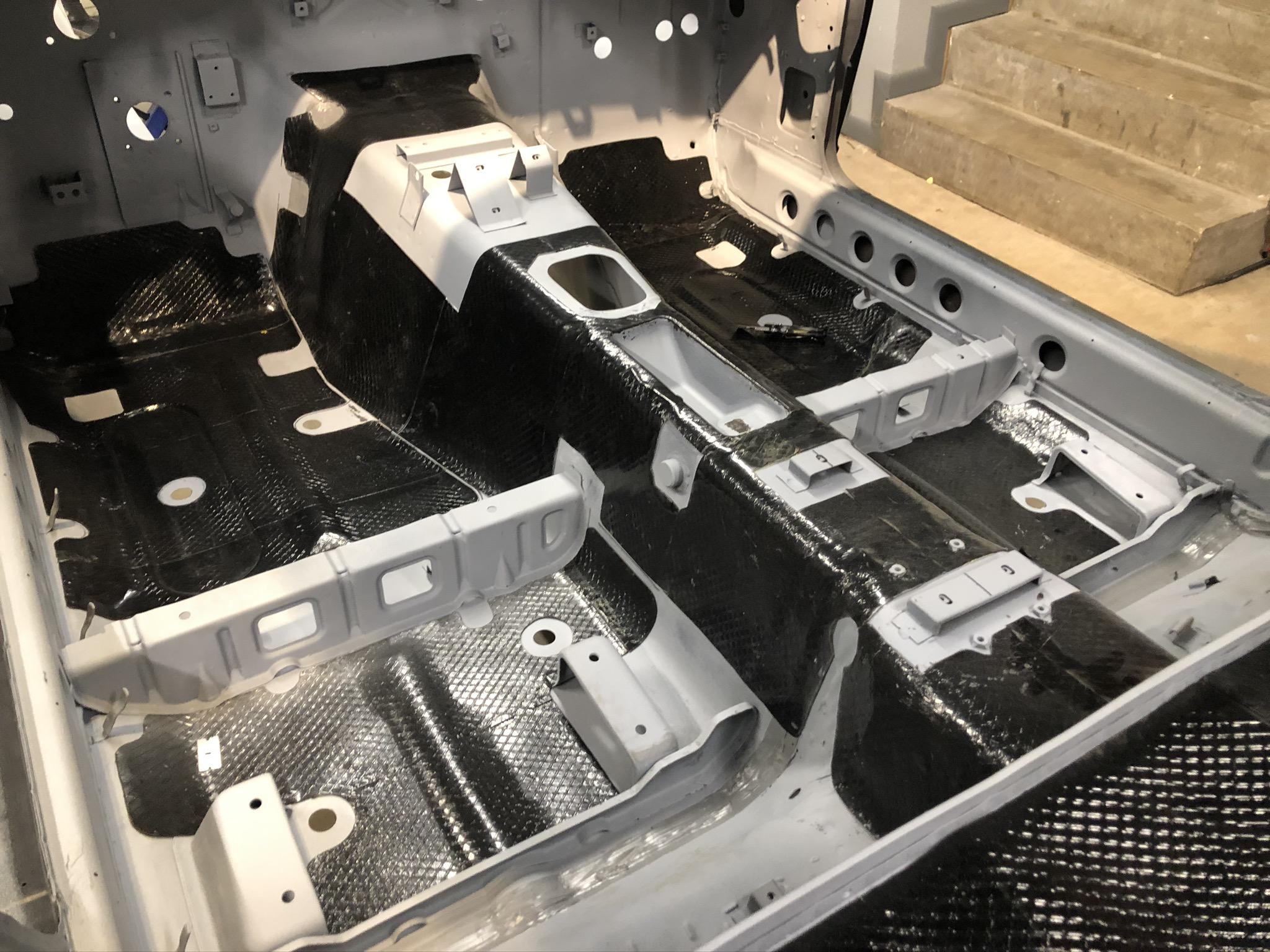
1 pointSound mat was installed in all the factory places prior to paint (including the floor pans). Firewall will get the fiber backed pad installed on it Floors before paint
 1 point
 -
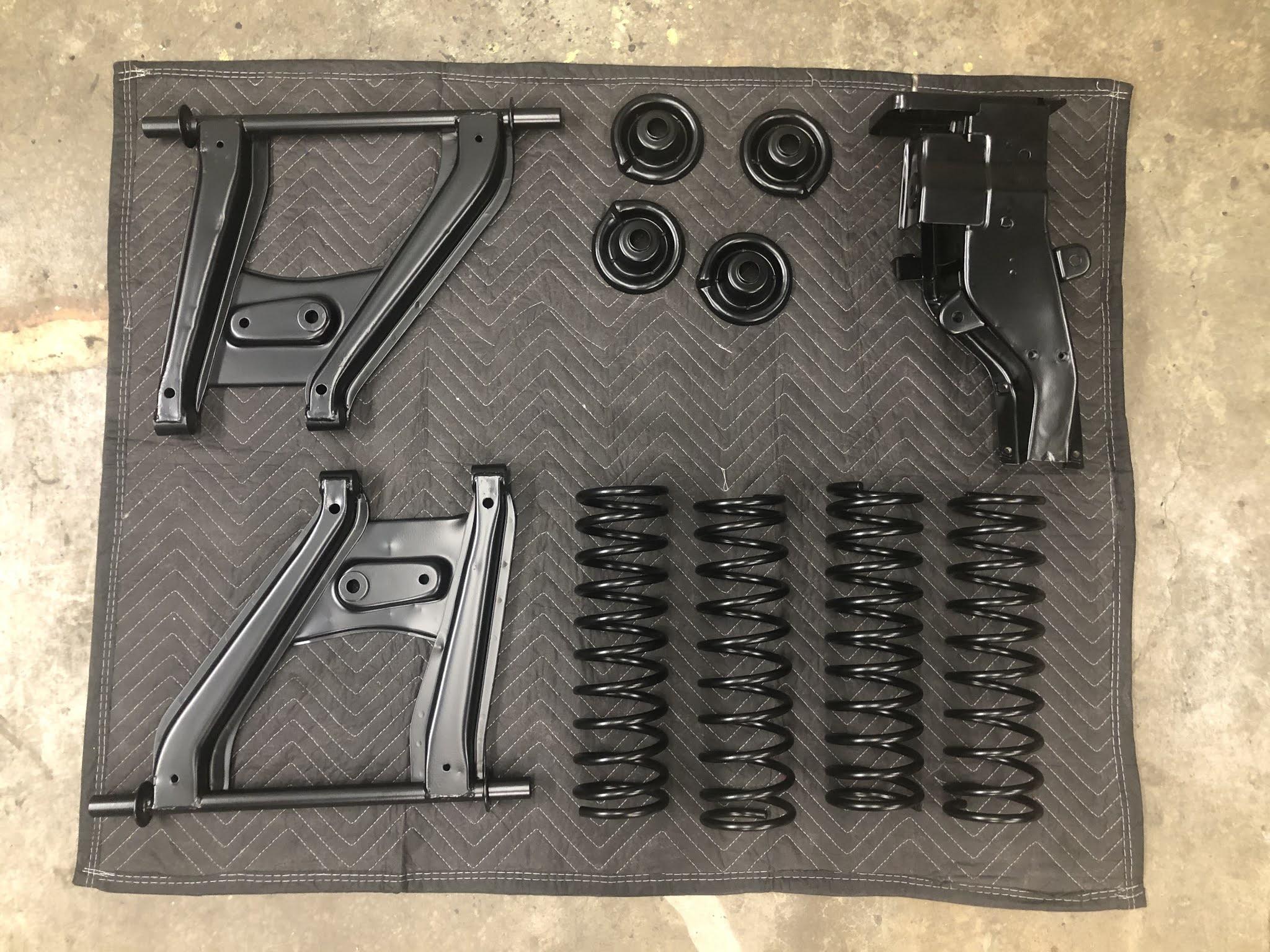
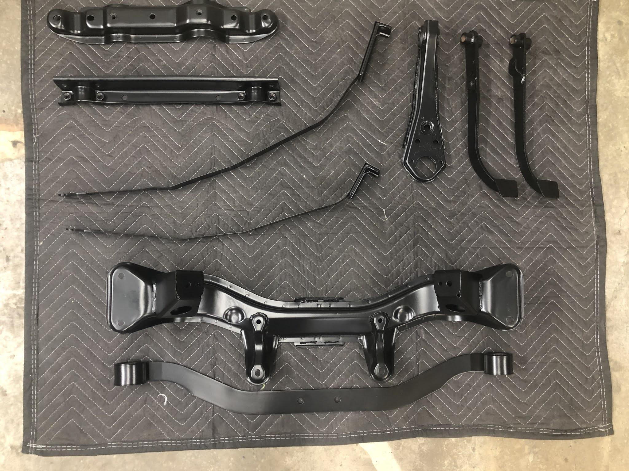
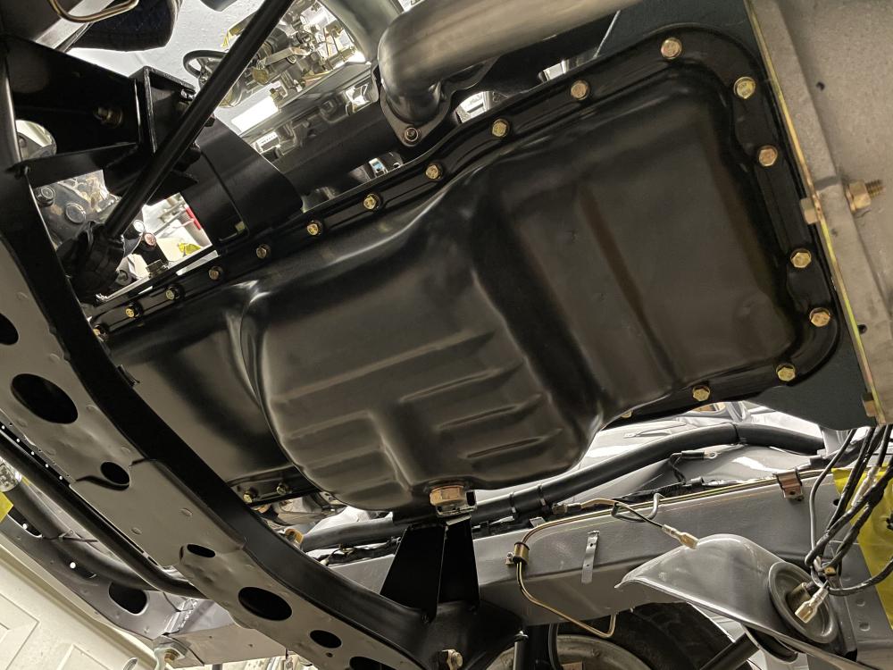
1 pointAnother big accomplishment on the Z, all the parts came back from powder coating. They look GREAT, super happy with the quality of work from the guys at Quality Powder Coating (oil pan and a few smaller bits didn't make the shot).
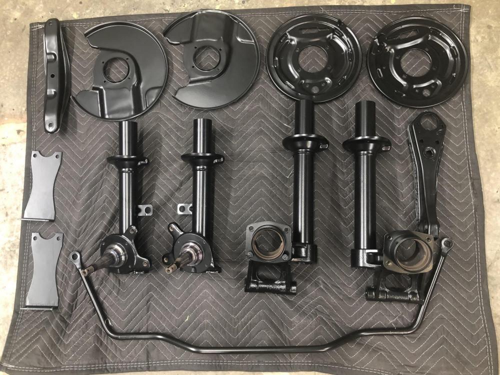

 1 point