


Topics Last 30 Days
Showing topics, images, events and files posted in for the last 28 days.
- Past hour
-
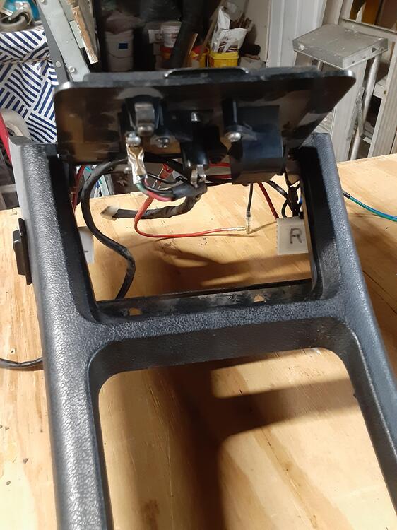
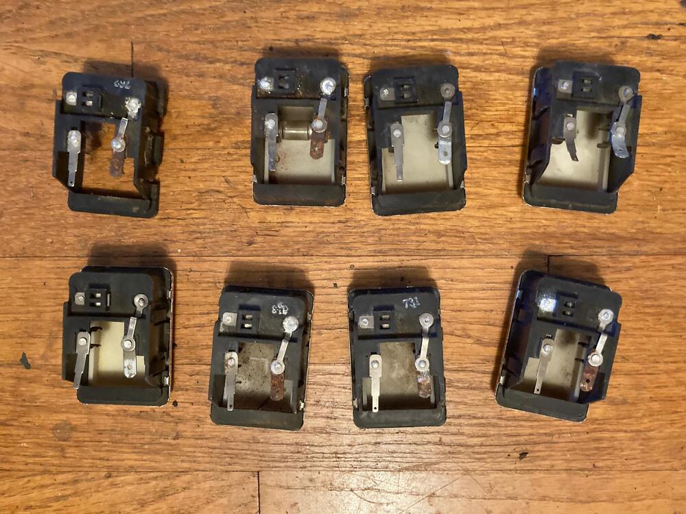
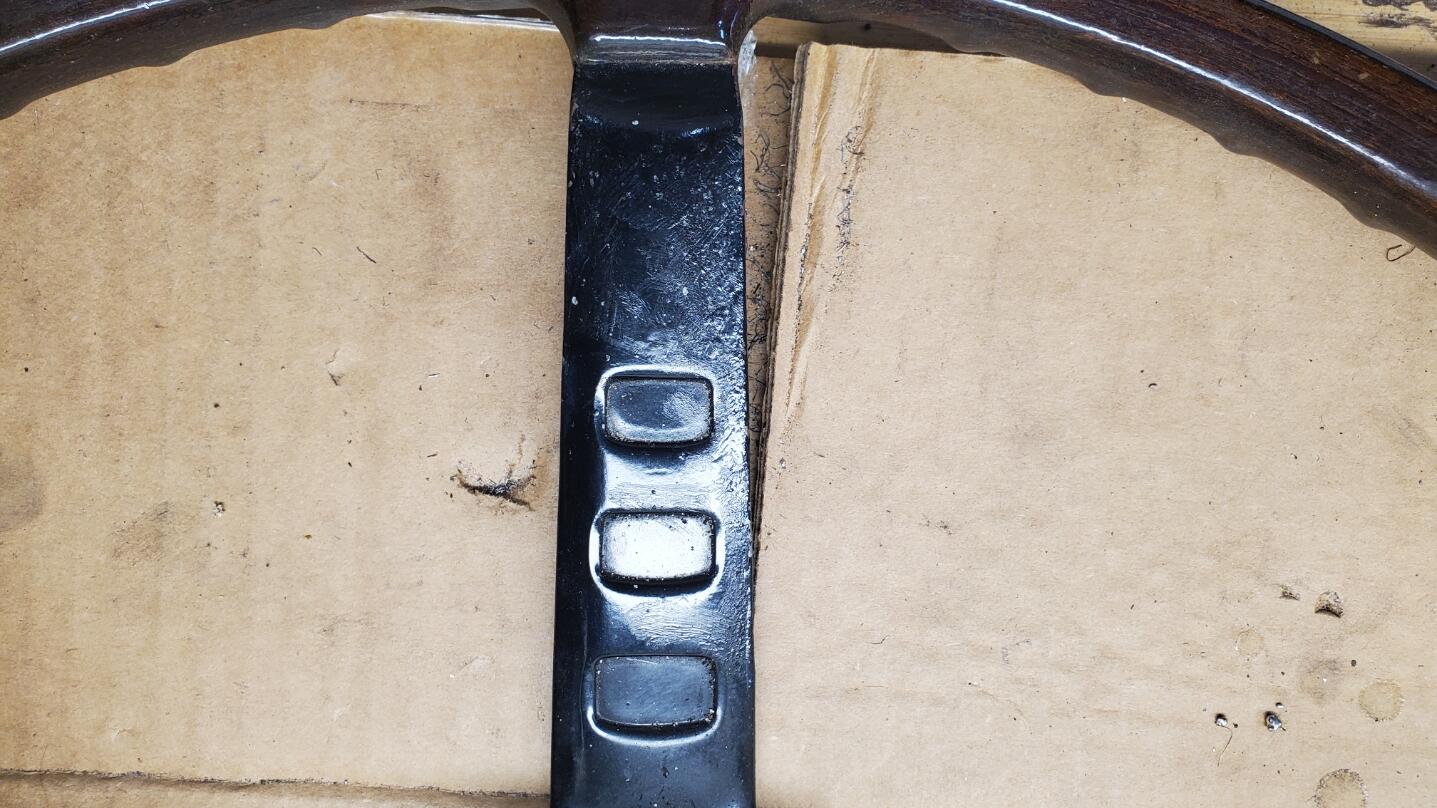
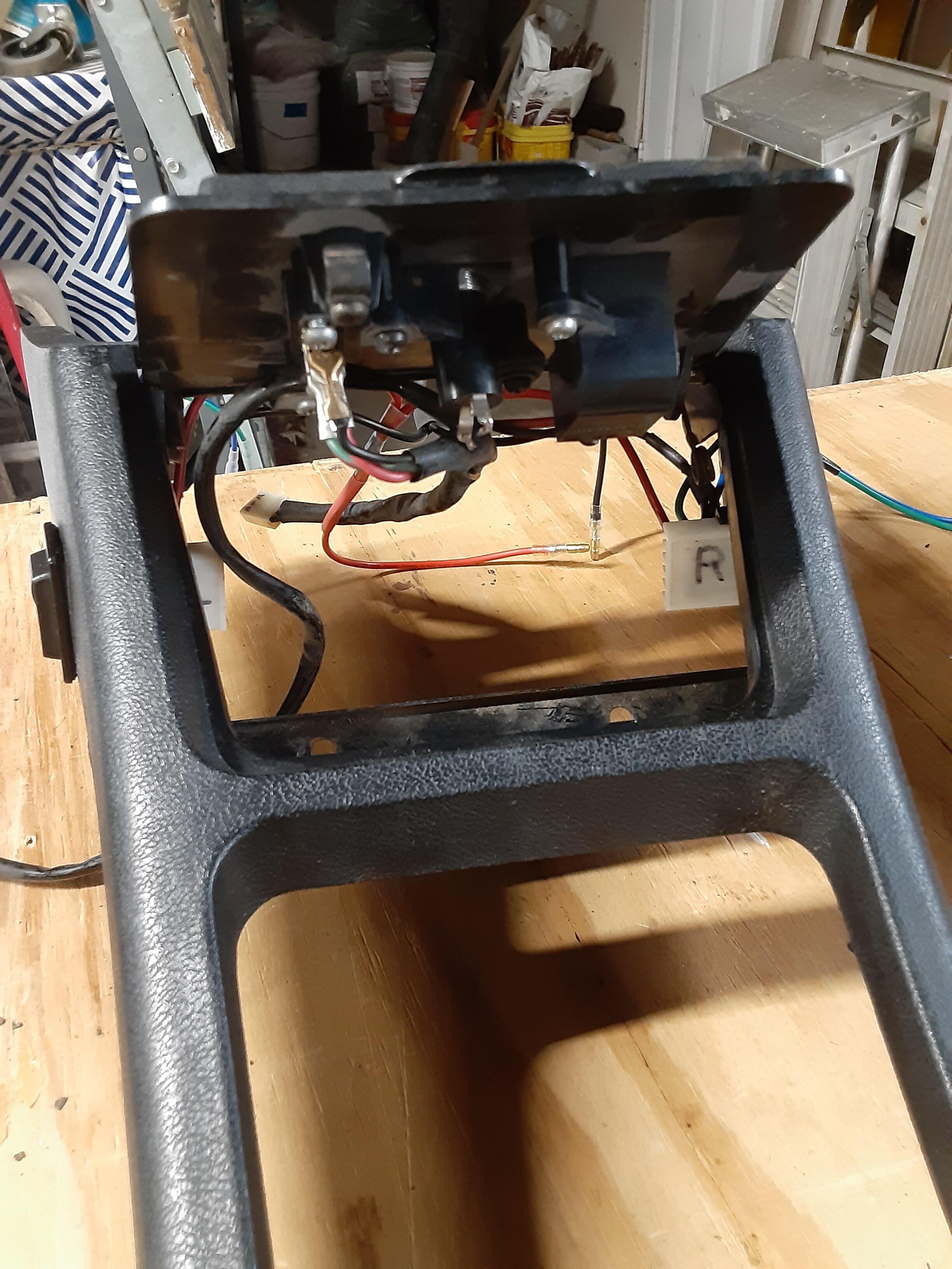
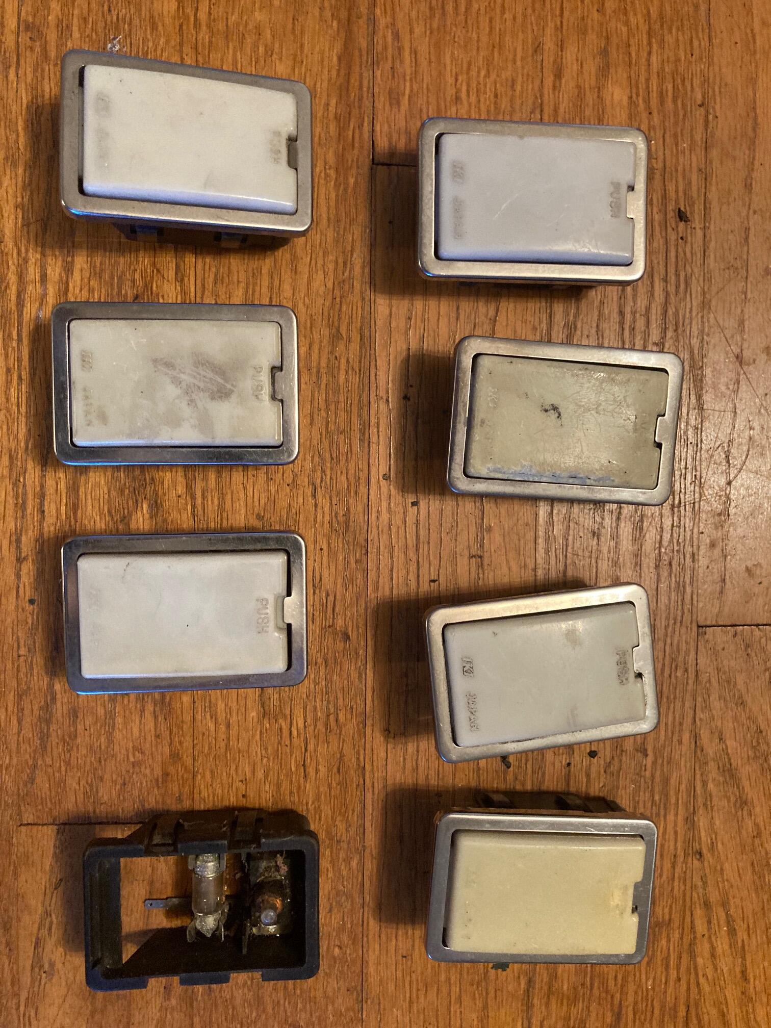
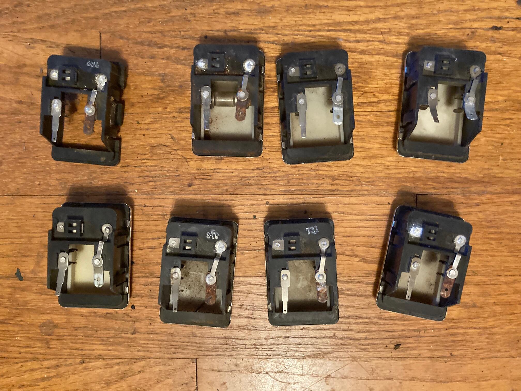
 Recently I got two set of two of the missing Pieces from my 240Z toolbox. I had a set which fit the image, but had different part numbers. Funny enough, now i have three different sets, all have slightly different shape or surface. some have different numbers, but appear to be for the same purpose :-) Despite being a bit corroded, i have at least now another missing piece of the puzzle. Thanks a lot to @26th-Z for your support! I had some free time, so i decided to get some small stuff done on the car. First thing to check off was test-fitting the headlights. Luckily, I always have a range of NOS and used parts on hand. I usually try to use old parts for test-fitting, so I don't mess up new parts, but in this case the old ones weren't really usable. So here we go: NOS headlight buckets and chrome rings, with reproduction rubbers (I will use the NOS set for the final assembly). And installed. You got to love the factory stamps on shiny plated parts. As usual, all bolts are temporary only for the mock-up. For the final assembly, I will use original fasteners :-) I wasn't first sure if the order of the assembly was correct, but it appears it is. And the frog got some eyes, again :-) Next was this choke assembly reinforcement plat made out of hardened plastic: As the name suggests, it's there to reinforce the choke assembly, which is usually mounted on the inside of the center console, and can get a bit wobbly. With this plate, it's instead mounted on the transmission tunnel and way more stable. It's one of these (invisble) improvements of the car, which I think really give the car a better feel. It's quite tricky to place correctly, though. But luckily I had a few completely broken center consoles, so the easiest way was just to drill the holes through the console And then sandwich it all together for test fitting. I also installed an old ashtray just to see if it all still works correctly. Now with the holes on the transmission tunnel. I will not use the original sheet-metal screws but instead have nuts welded on the outside and use machine screws, so it looks like it's a factory thing, from the outside. And the interior mock-ups are coming along. Driver side seat rail, passenger side footrest and center console (With choke assembly) is installed and looks good. Ignore where the choke wires go. They're just there for easier installation.
 - Today
-
 Are you talking the old knee... 😁
 -
 Glad to here that my suggestion hopefully was given some thought.
 -
 Someone is going to get a good buy. With the insignificant defects, half of the bidders will be scared off.
 - Yesterday
-
 You can check fire at each plug with a 12v light but before that you should make sure the firing order is right. 153624 which is not the same as a straight 6 Ford or Chevy.
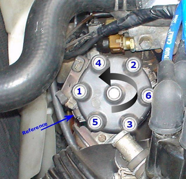
-
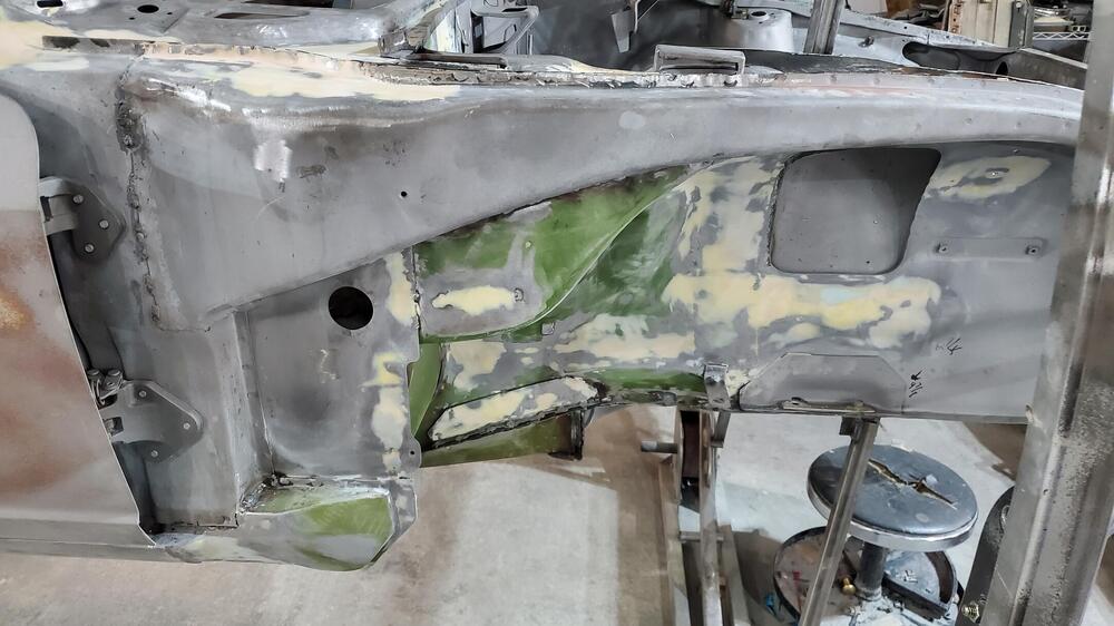
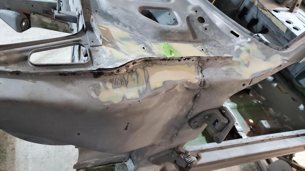
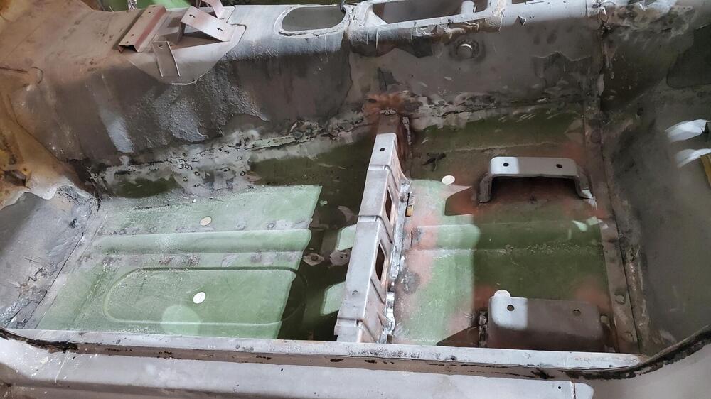
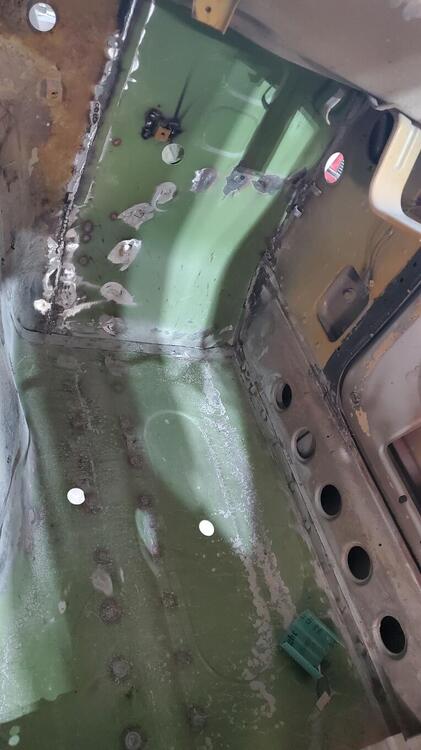
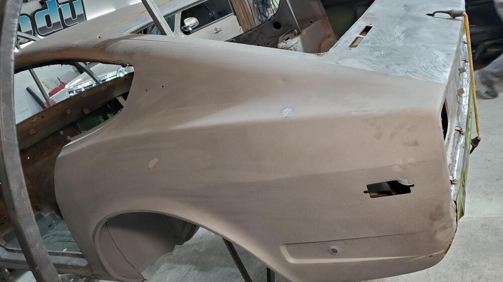
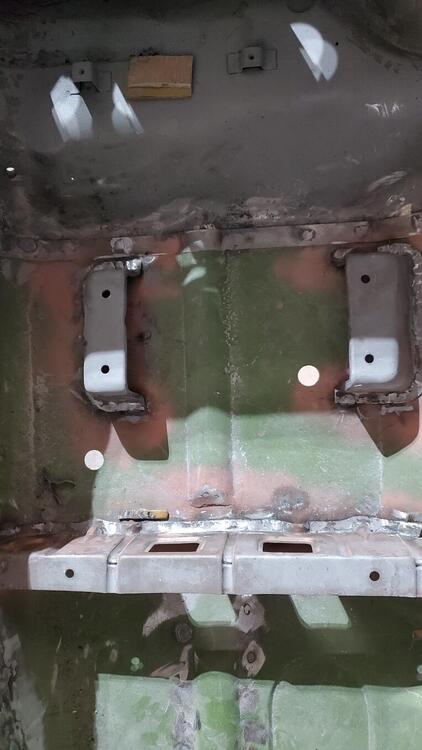
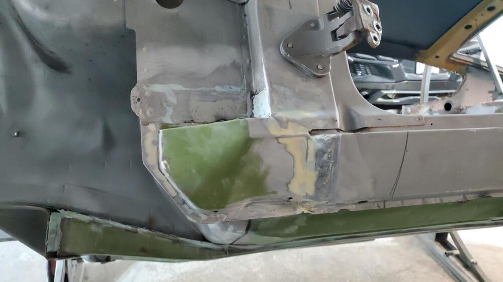
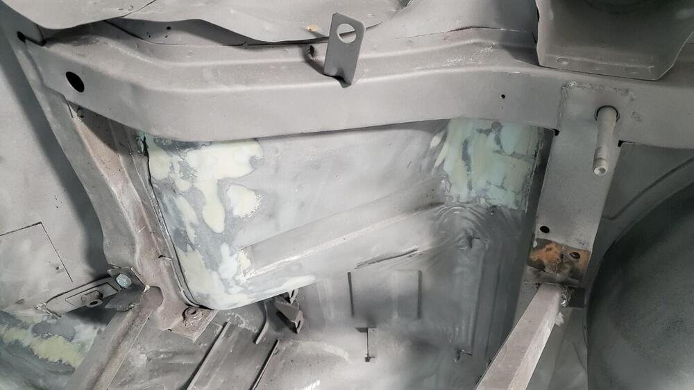
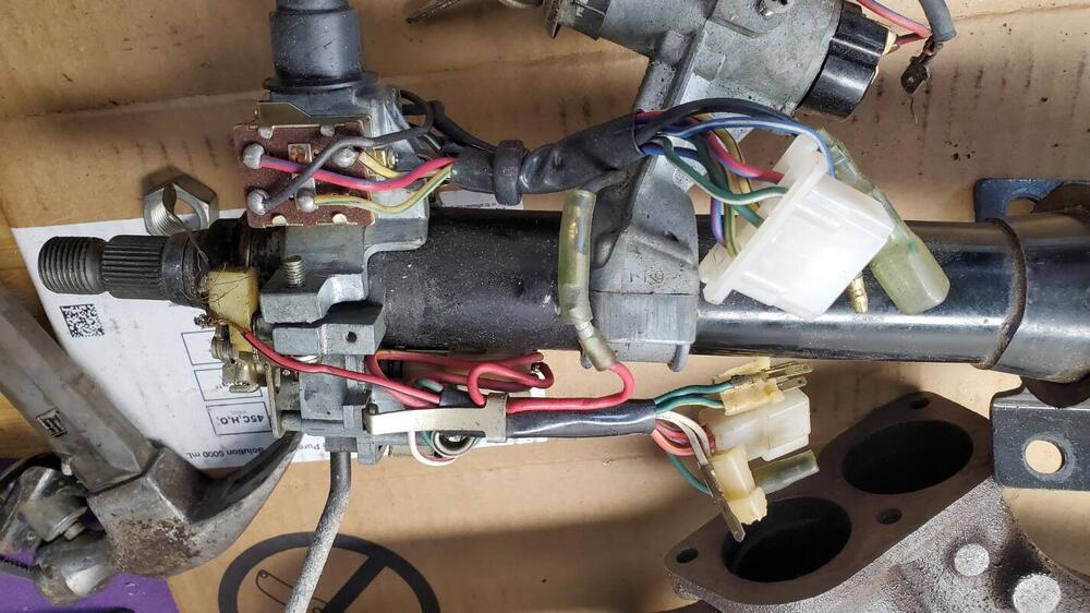
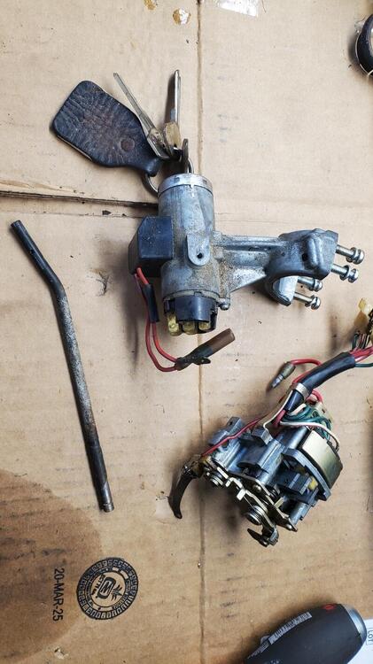
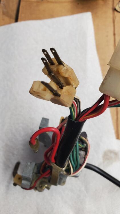
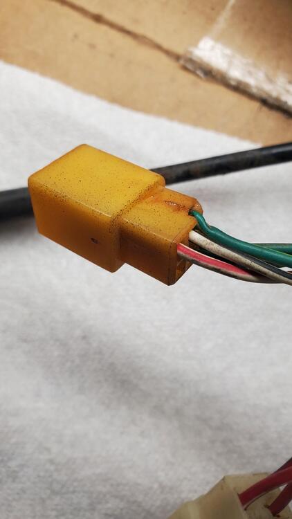
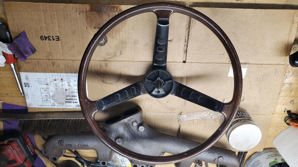
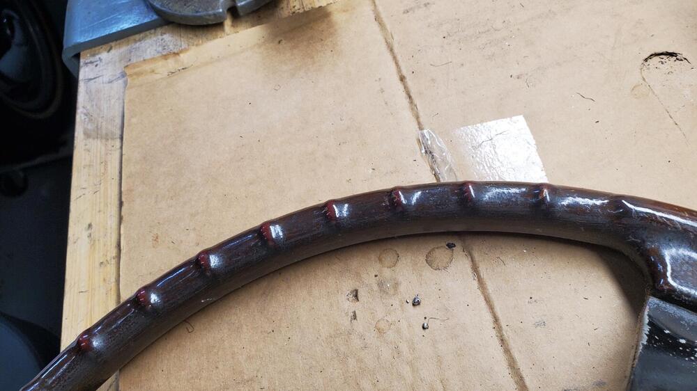
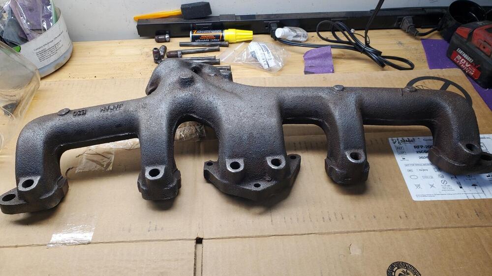
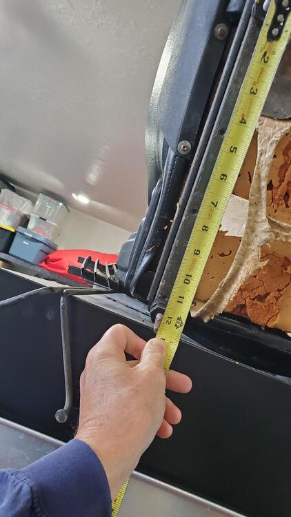
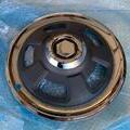
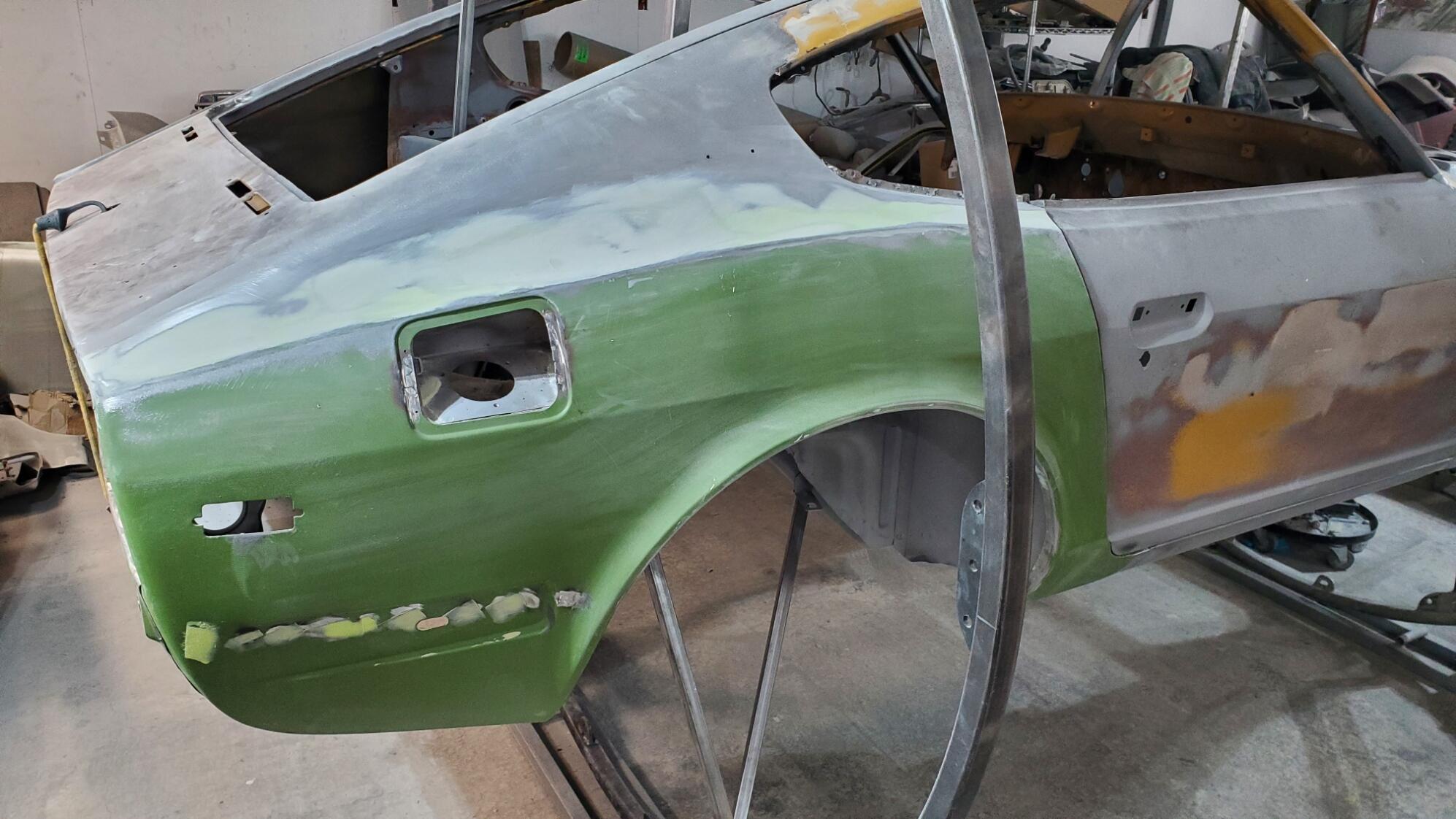
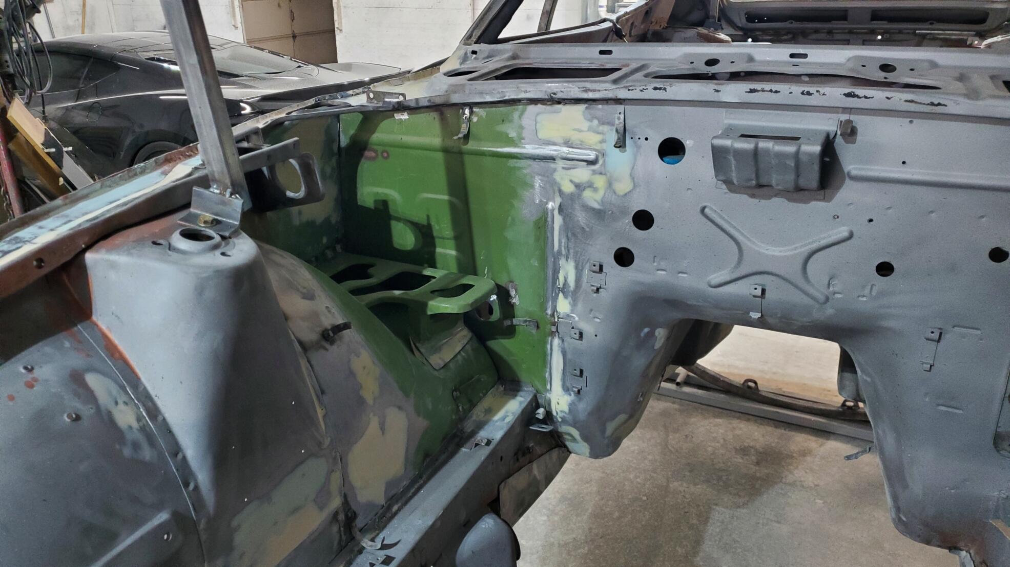
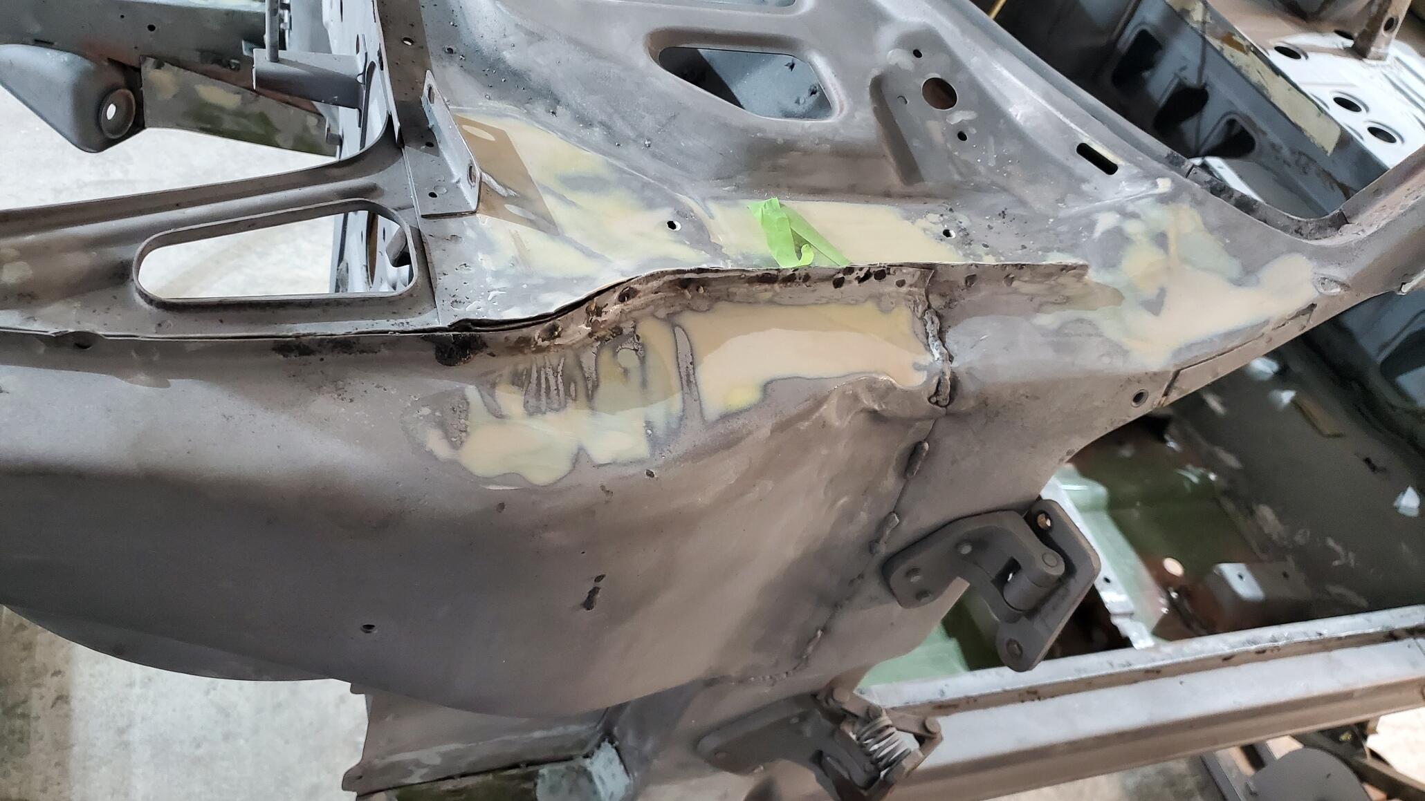
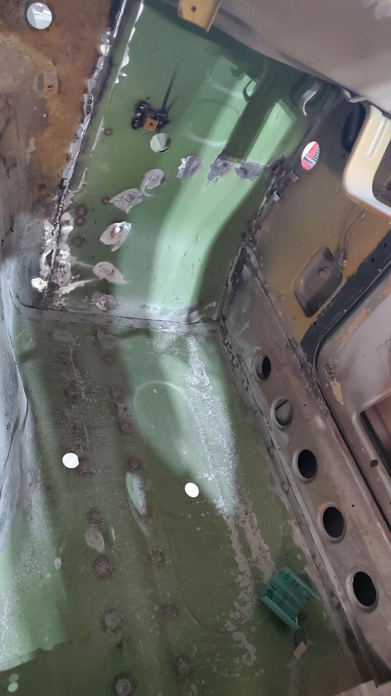
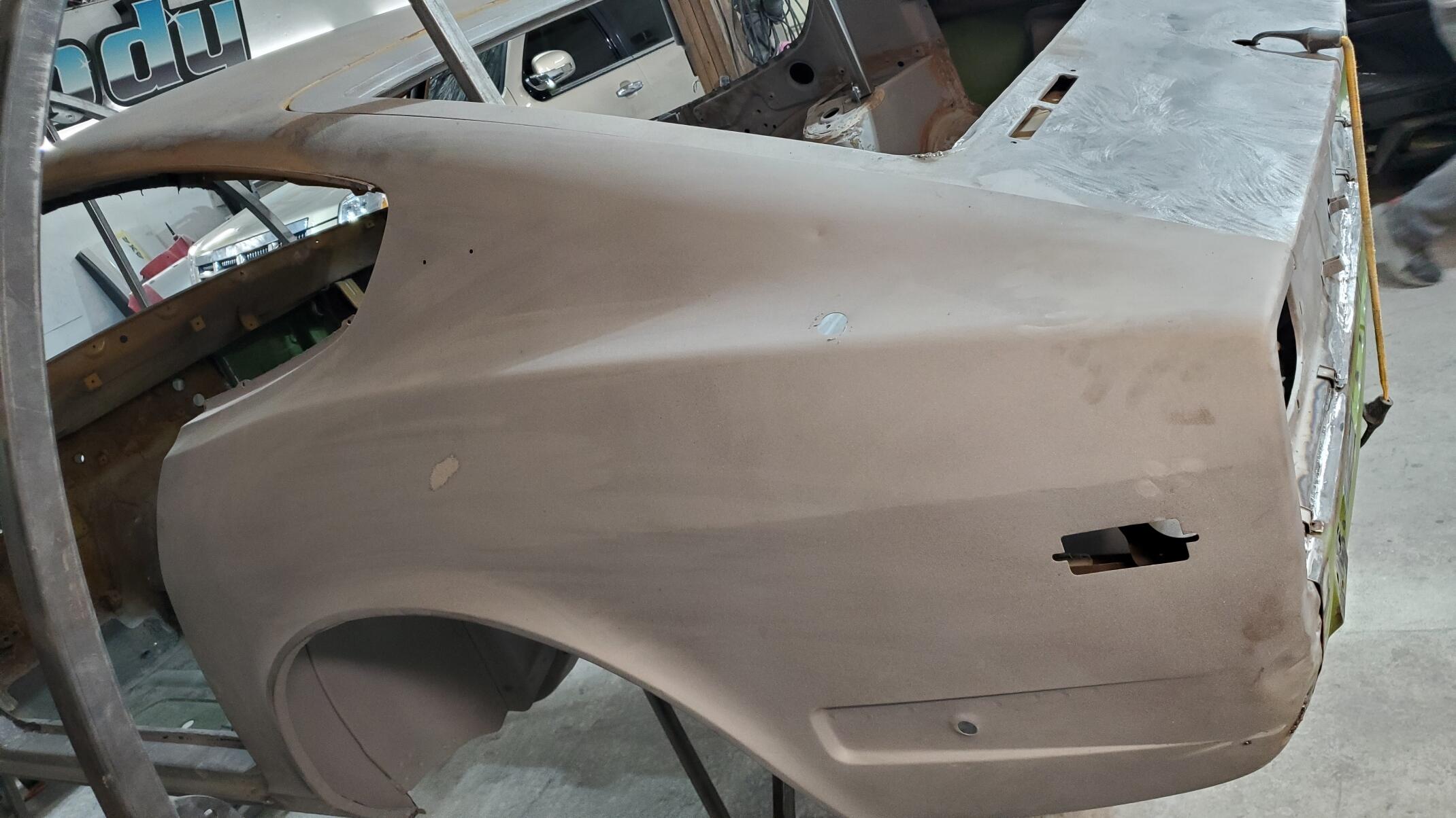
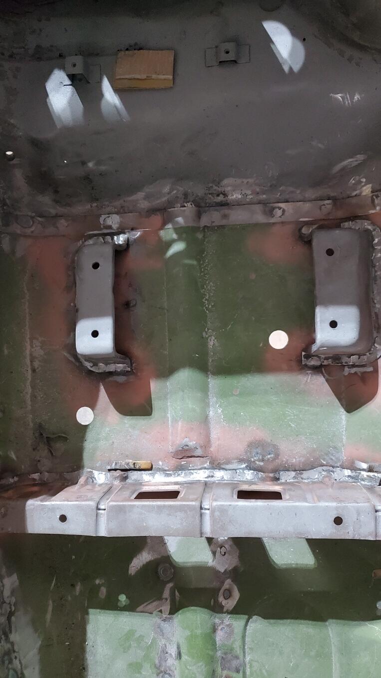
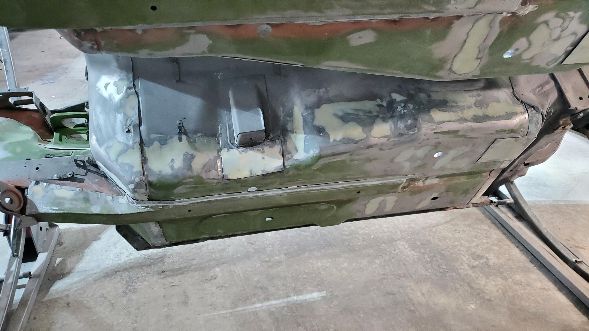
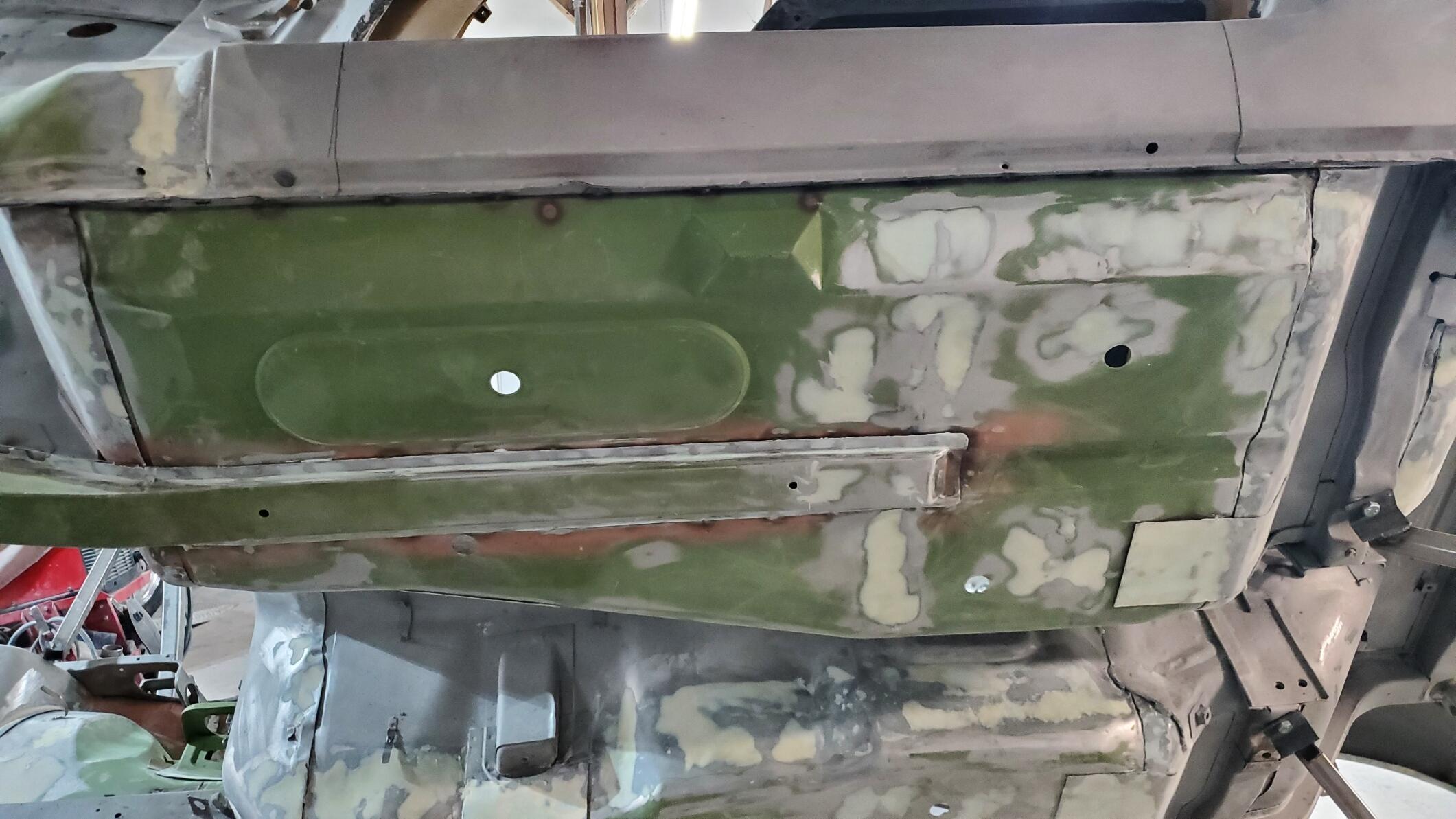
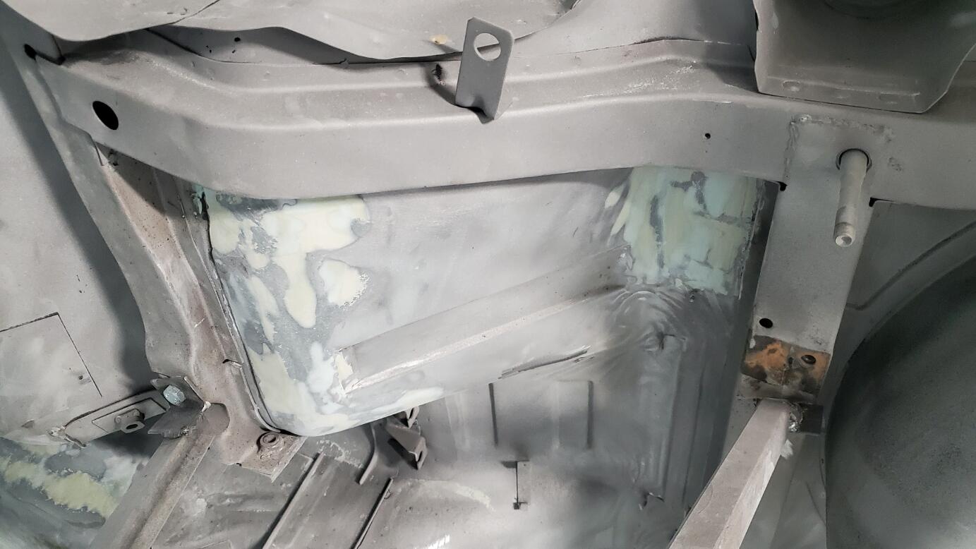
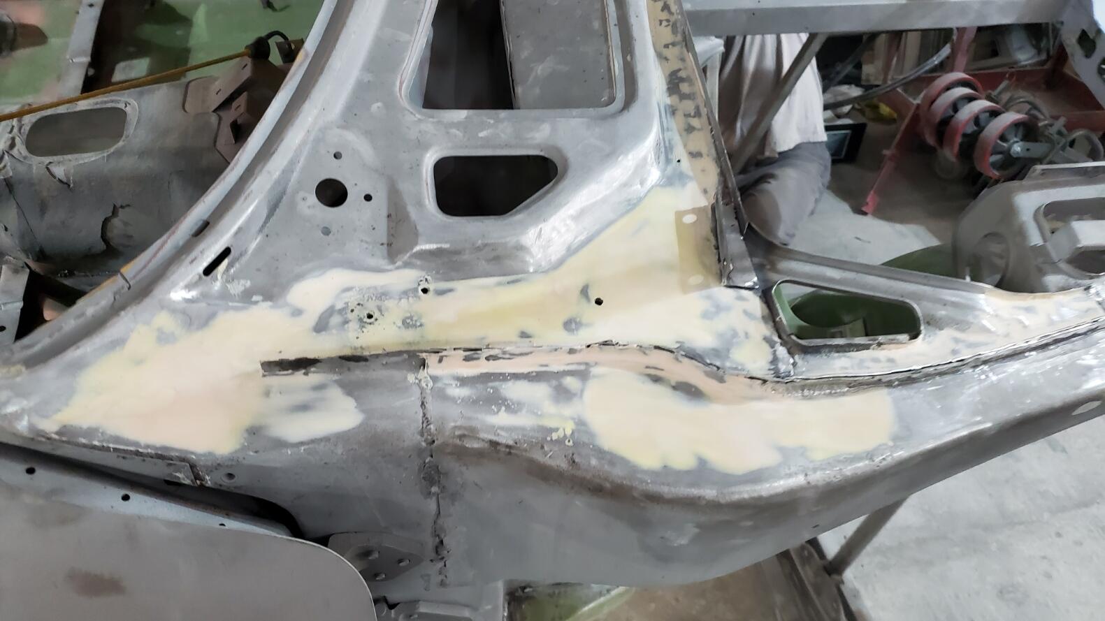
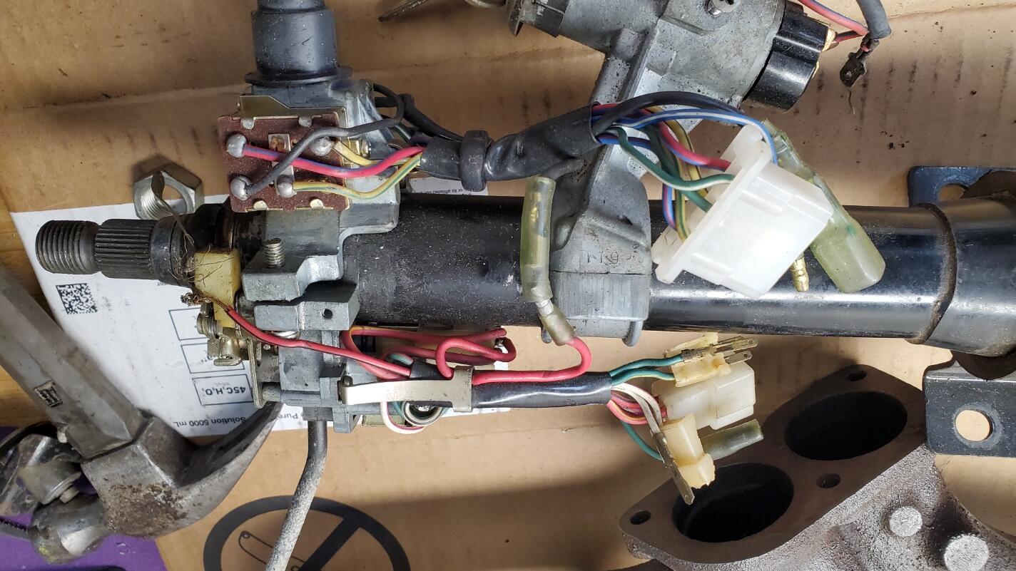
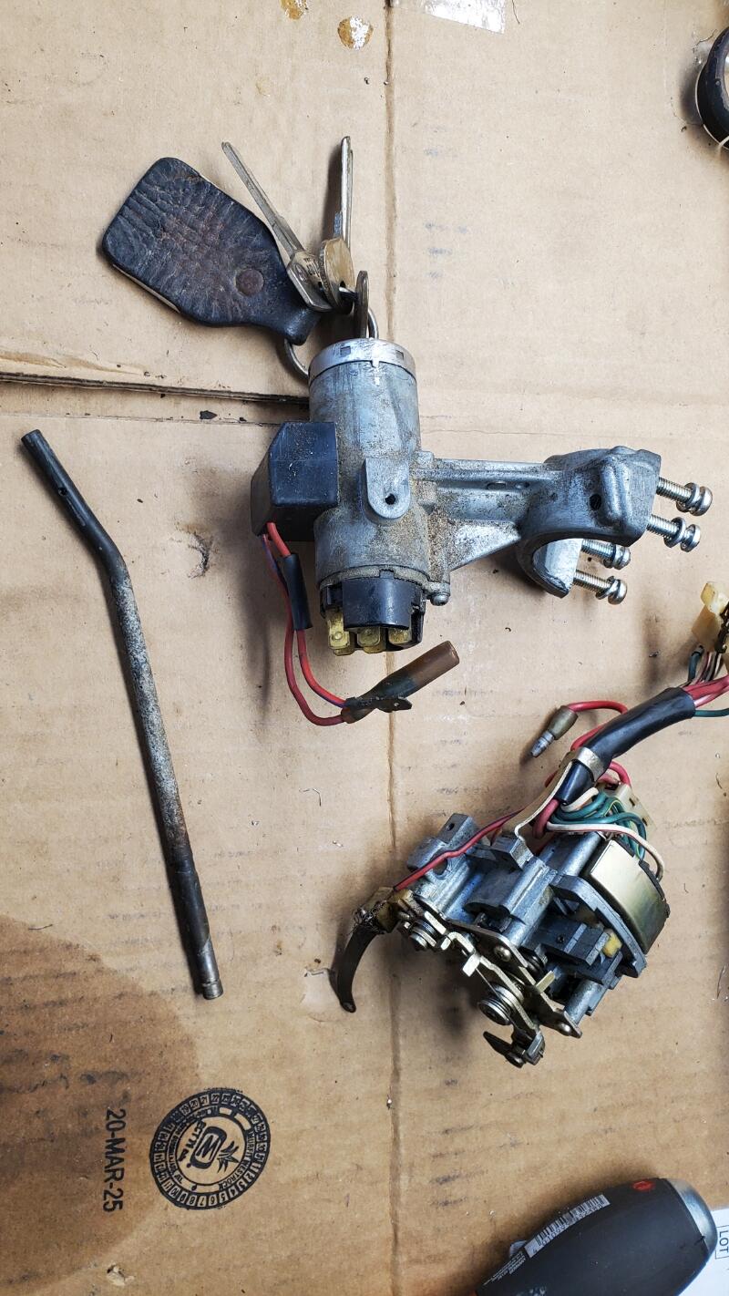
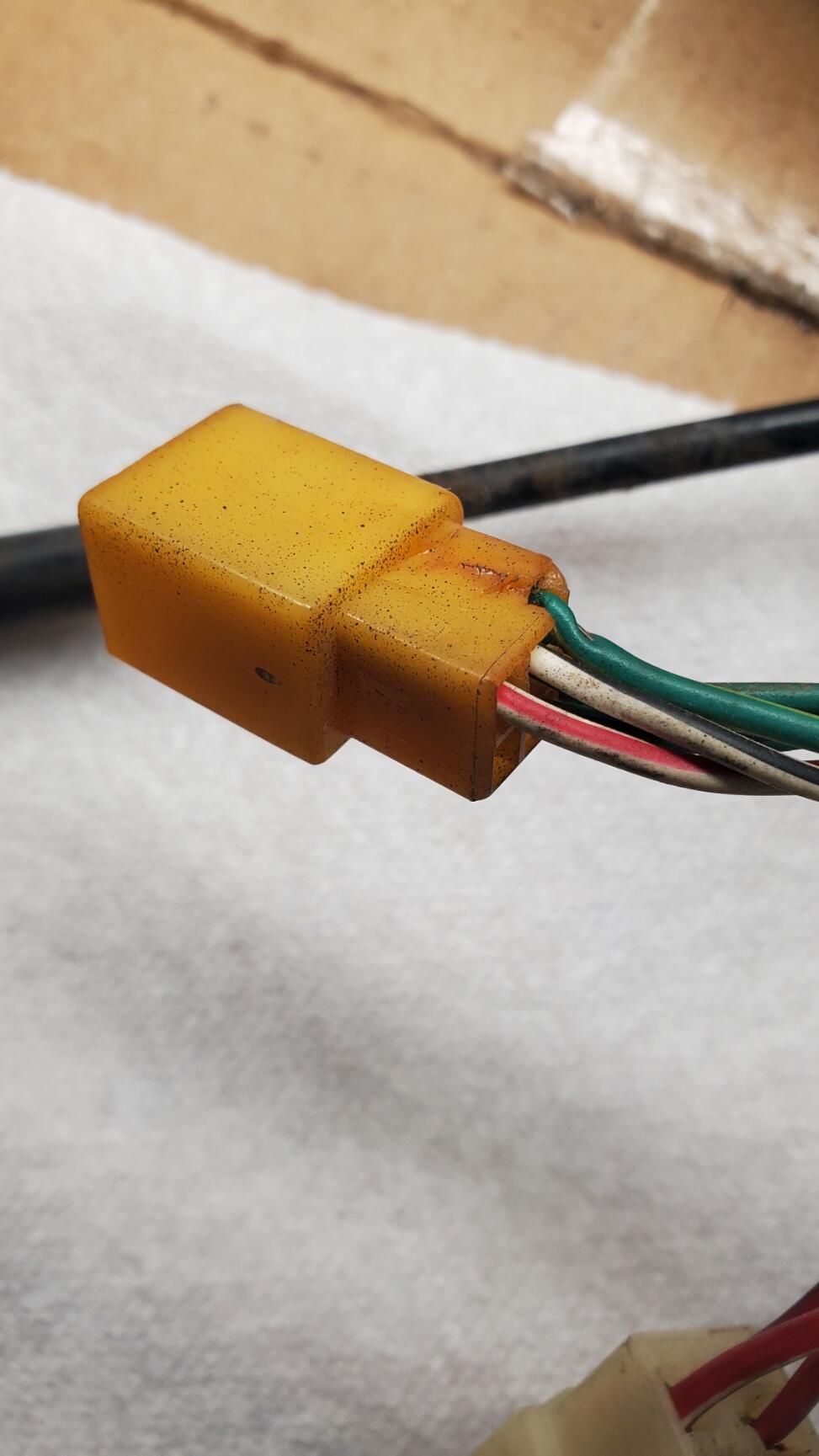
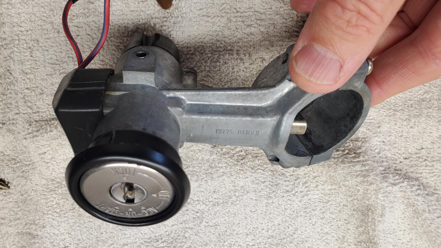
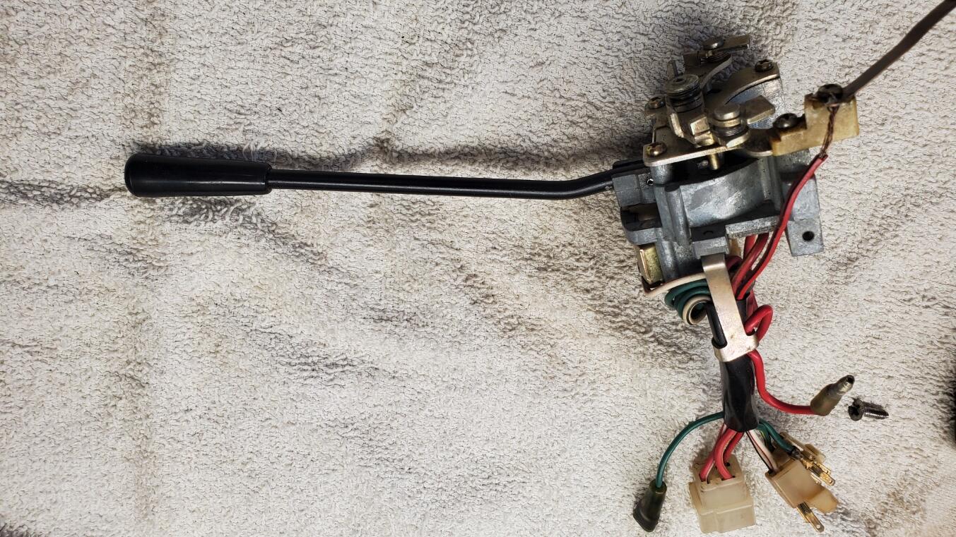
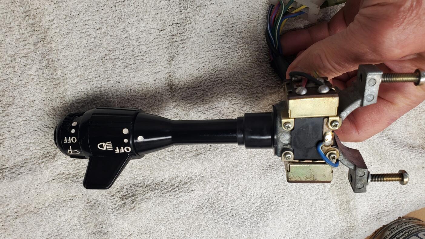
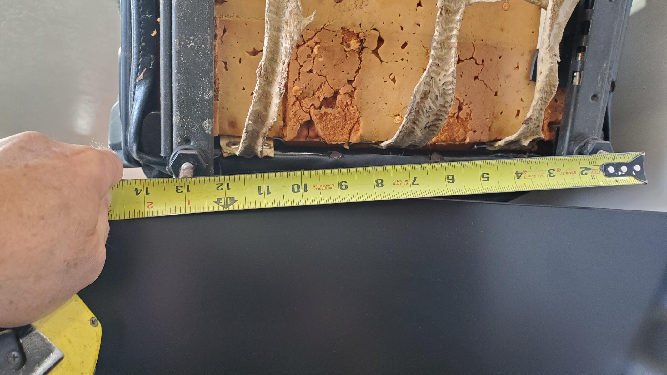
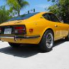 The body shop work continues and looks like things are moving along nicely. I am happy to see that they are being very thorough and even cleaning up areas that no one will ever see. I did check the seat mount locations. The rear inboard bracket on both the drivers and passengers side is off by about 2 inches (both are too far outboard). Carlos has a welder and will do the re-mounting of the bracket. I did contact Larry, the original metal work guy, to point out the error. Looks like we will get that re-mounted for no additional cost. I also sent pics of the dimesnions from the seat rails. The dimensions that I measure are 13.0" wide (330mm) and 12.75" deep (324mm). I removed the air galley from the exhaust manifold, but was not able to salvage it. After repeated heating, cooling and lube applications, I was only able to get 2 of the fittings out. By this time, the hex portion of the remaining fittings were starting to get pretty trashed, so I ended up cutting the tubes on the remaining 4. Fortunately, I did not have to do any re-tapping of the four difficult fittings. I was able to drill away most of the metal in the center of the fittings and sort of peel the threads off of the manifold. This made is easy to save the extension tubes that are secured by the fittings. On all of the previous cars that I have restored, I have always used a gray powder coat finish on the exhaust manifold that Les Cannady at Classic Datsun Motorsports always uses. Since we want to be very exact on the reproduction, I was considering a high temp cast iron paint which would be closer to the original color. However, it was noted that those typically peel even with the best prep and application. POR 15 was recommended, but again, this ends up being a colored paint and softens the texture of the original cast iron and doesn't really replicate the original color. I eventually phoned Rod Schmitt of Rod's Garage (Restorer of the 2025 JCCS Best of Show Red 240Z and John Morton's 1st place Green 240Z in the 240Z category) to find out what he uses for the final finish on the exhaust manifold. Rod says he cleans the manifold well with wire wheel and then uses a couple light coats of graphite spray for the final finish. He says this comes the closest to the original color and finish. It also handles the high temps well. So, this is the current plan for the exhaust manifold finish. I have started cleaning up some of the steering column parts. Some before and after pics are attached. It looks like these components have been accessed previously as the turn signal mechanism had a wire that was just twisted together with an extension on the horn circuit, so I removed the extension and soldered the wire in place. It has a broken connector which I thought I could replace with another signal mechanism that I have but that replacement was just as brittle as the broken coneector, so I just ordered a new one. Also, the headlight mechanism looks surprisingly good, so I am thinking that may have been replaced as it looks virtually brand new. Typically, these are pretty gummed up and the white parts are yellowed and/or dirty. This one looks untouched. I will re-restore the steering wheel as the previous restoration is poor. The black paint is thick and uneven and should be a satin finish, not gloss. The 'wood grain' portion has a heavy gloss finish, should be light satin or semi-gloss, and the back side with the 'nubs' was over sanded so the wood grain appearance is missing on the nubs.
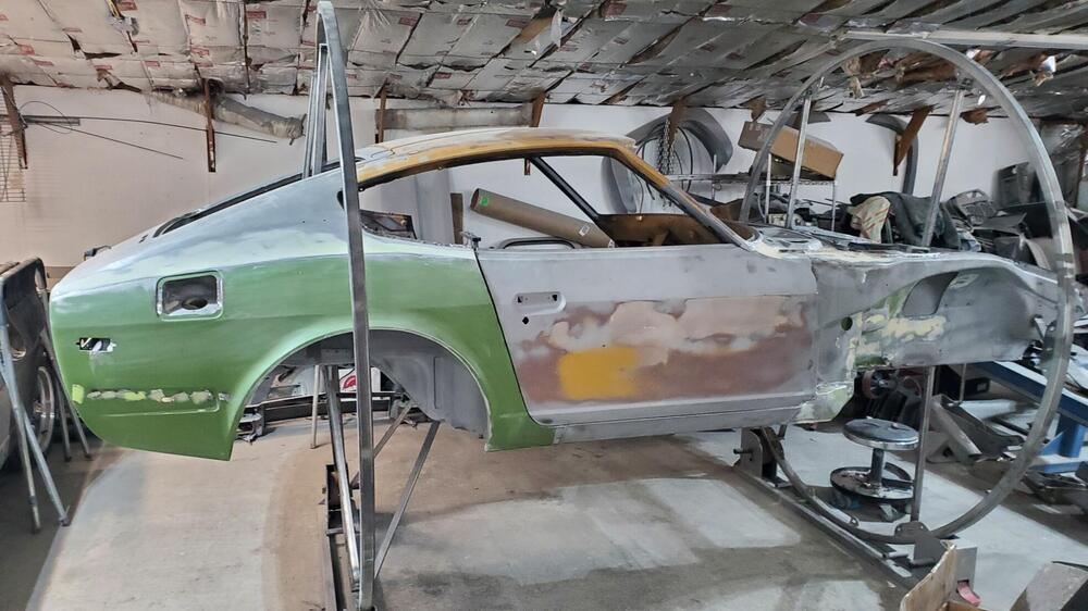


- Last week
-
 I'd take a test light or meter and see if the wire to the small spade connection on the solenoid is getting power when you turn the key to Start. You might have a cylinder full of coolant. Who knows. If you're getting power to the solenoid but it doesn't do its thing then you might have a bad starter/starter solenoid. Hit it with a hammer.
 -
 Sorry to resurrect this old of a thread (it's been informative in my research regarding luggage straps) but how cool is that?! The S30 with the VIN HLS30 00240. That's a keeper!
 -
 Hi Trisha, see post on 240Z International Registry Facebook Page. Kelly Jean is looking for pictures like your car. She wants to make a clock as it was her first car. Cheers, Kirk
 -
 Better question is what is that carb for... Sorry, no love for those with me.
 -
 I'm happy with how the dove tails turned out so I'll go ahead and have a batch made up if anyone needs them for a restoration. Just sourcing the right JIS screws.
 -
 240 or 260 manual wanted to trade for 1969 Plymouth GTX 440 4-speed
 -
 I'm really impressed with the carburetor set-up. That's a very valuable car, and with some provenance, perhaps? That should be worth at least one year of med school!
 -
Light. Console. I think G/W is clearance, gauge lighting, and etc. but I'll look... 72_dash_2.pdf The 240Z dash I have has that same connector - the entire dash and harness is unconnected so... But - the G/W on that connector traces to the small 6-pin Body Harness connector shown in that .pdf - G/W in the upper right corner of the connector. The body harness G/W goes back to the clearance lighting in the tail. Trace that Red - I think it may well go to the front (engine bay harness) and the two hidden Fog Lamp connectors in the harness as it spans the radiator core support. And as you know the US model did not come with a Fog Lamp Switch from the factory so that would be an unused connector if what I said is true. Oh, if you look at the first wiring diagram in the FSM (not the "US and Canada Only" schematic) you'll see Fog Lamps and the connector for the Fog Lamp Switch. BUT, it'll confuse you because it shows a R and an RG wire to the switch. If you trace the RG, you'll see that it "tees" off a GW. So maybe the schematic doesn't follow the harness build exactly or vise-versa...
-
If you're going to have a muffler shop do it why not them look at it and use their database to find one. If you're going to do it yourself, then trying the no muffler twin stack should be easy. If the dimensions are correct. Looks like what you have is clamped on, not welded. So trying some things should be easy.
-
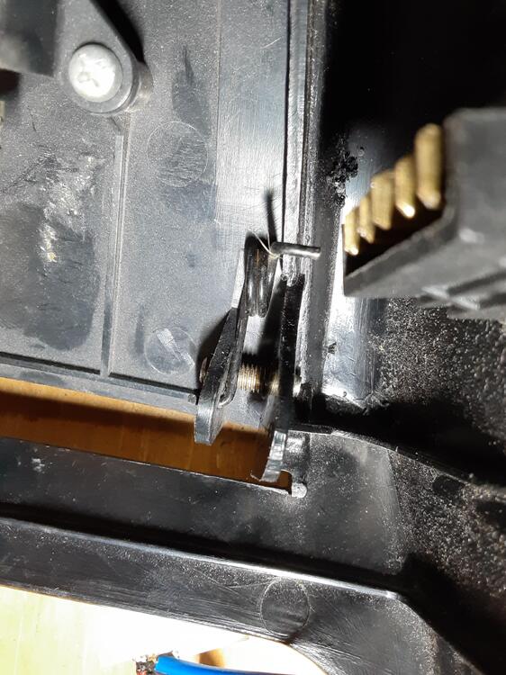
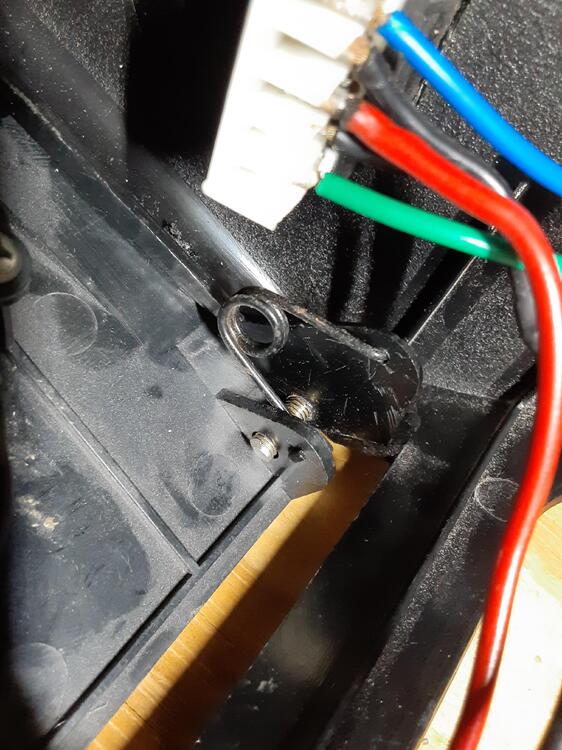
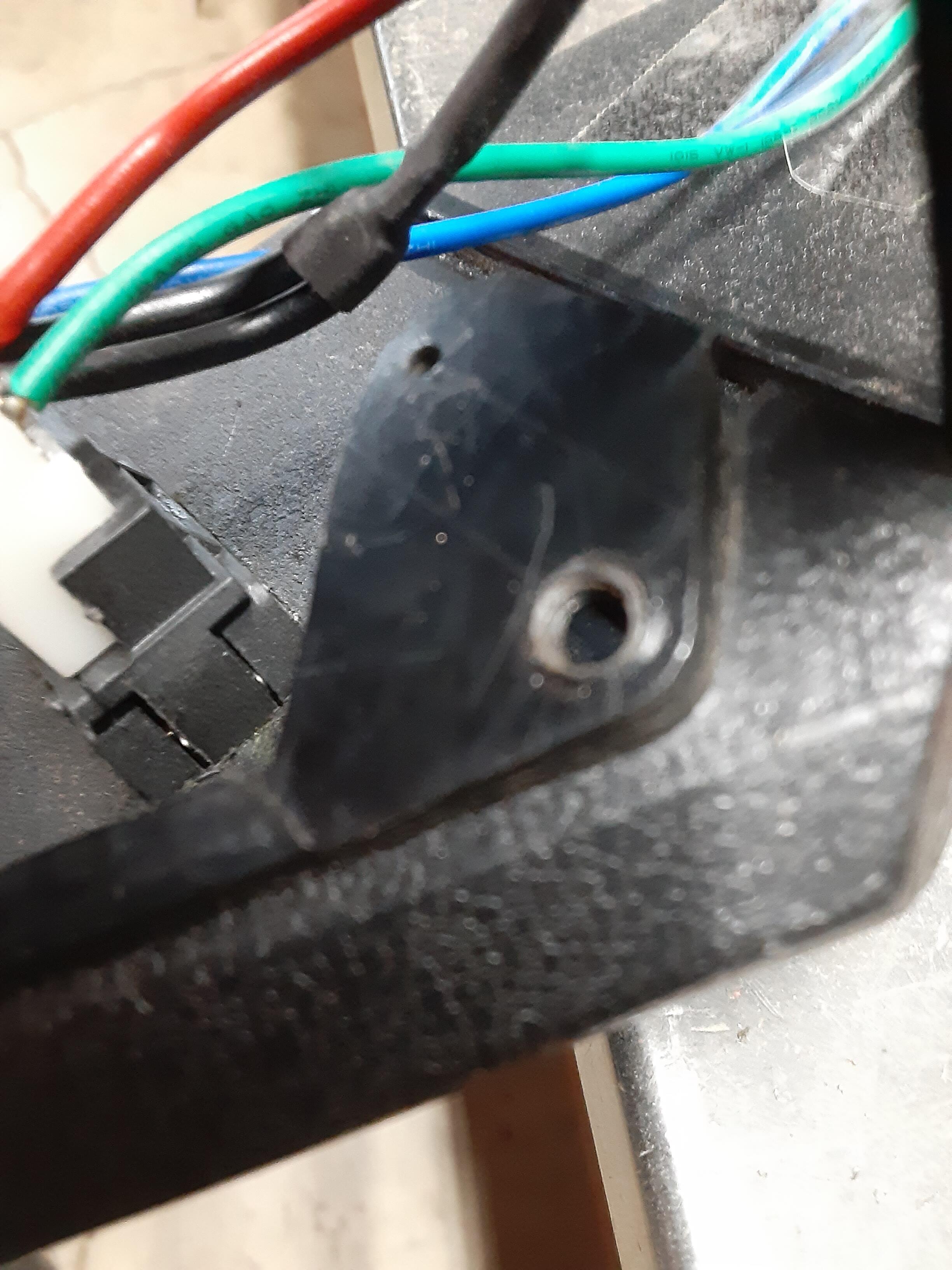
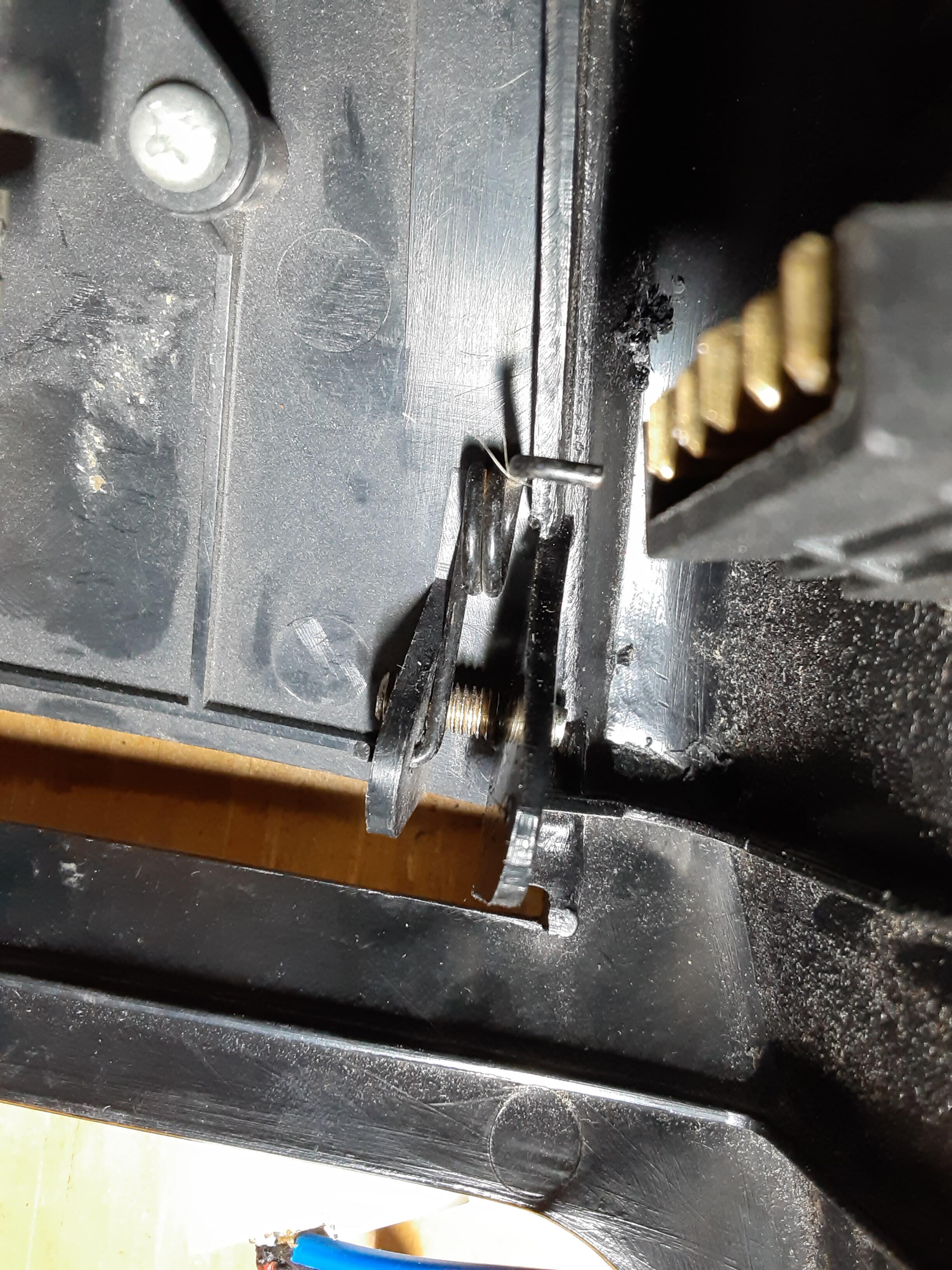
 Well, no one came to my aid on this matter so I've solved it as best I could using a metric bolt to replace the missing plastic pin. I measured the left side plastic pin diameter as approximately 4.7 mm. This is close to the 4.7 mm diameter that I measured on a 5M bolt's threads. The hole on the tab on that side of the cover comes in at 5.3 mm so there is about 0.6 mm of "slop" when the pin is in the hole. The hole on the right side tab measured 5.8 mm, almost exactly the diameter I measured for the threads on an M6 bolt. I was a bit squeamish about using an M6 bolt as there would little, if any, of the kind of slop as exists on the other side. So, an M5 bolt it was. But I do have the option of swapping in an M6 if I feel the need. I started by creating a small divot in the middle of the broken pin's location. Then, starting with a 1/16" drill bit (Hey, I ain't got metric drill bits), I gradually increased the hole size step-by-step using the next larger drill bit until i finished with 5/32" bit. I then slowly tapped the hole with a 5 mm-0.8 tap. Note that my tap and die set says to use an 11/64" drill for this but I wanted to have plenty of plastic "meat" for the tap to bite into. With that done, I took a 5M-0.8 x 30 bolt and cut off the hex head to give me a crude stud. I threaded this into my hole so that just a little tip of the stud showed on the side where the tab would eventually be. I then put the cover on the remaining plastic pin and, using needle-nose pliers, rotated the M5 stud so it engaged with the tab hole and then a bit more for good measure. I was going to epoxy the M5 stud into place but decided to not do so now at least because things are working well and it will be easy to retract the stud if I need to remove the cover at some point. I LOVE field engineering.
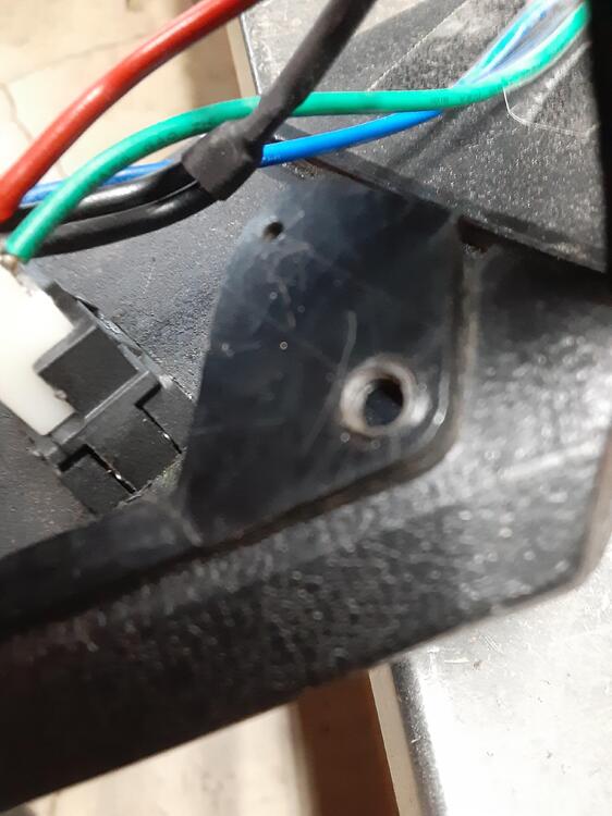
-
-
 Excellent analogy. That's a great philosophical thought exercise. Wonder what the right answer is.........
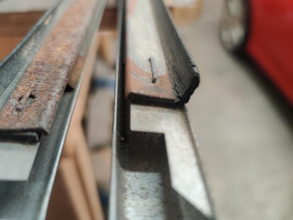
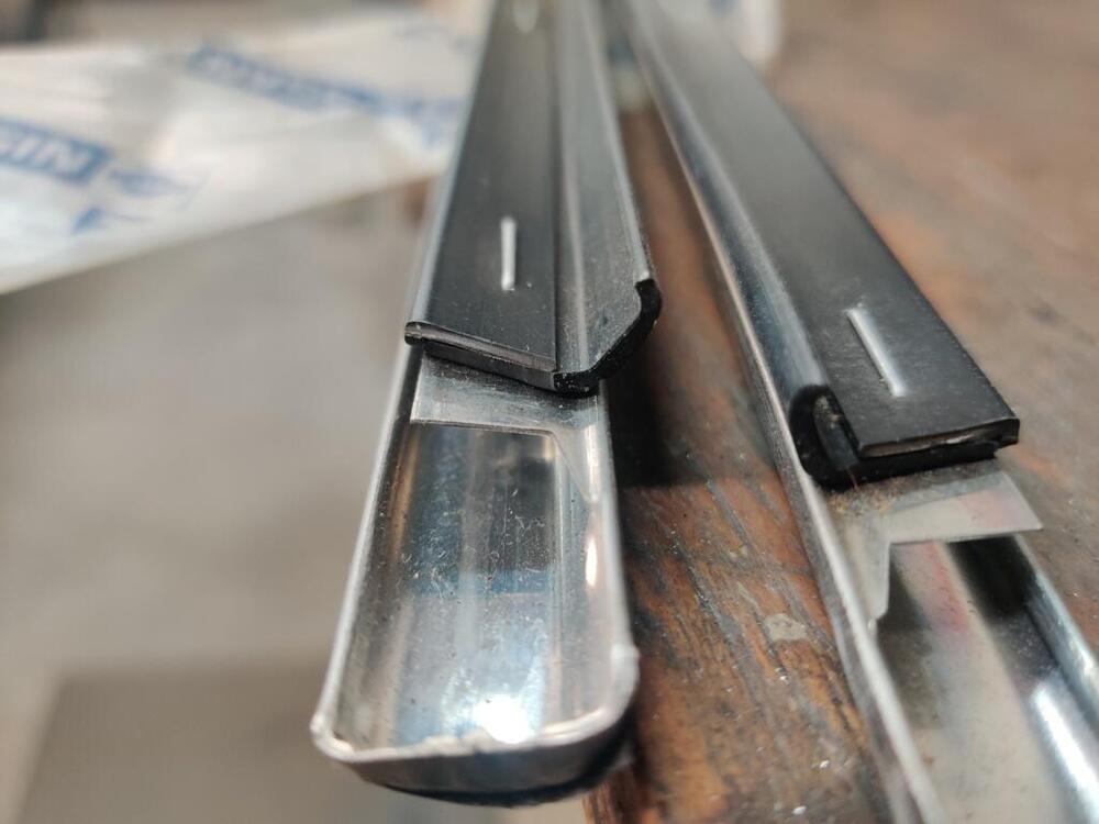
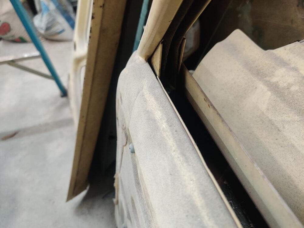
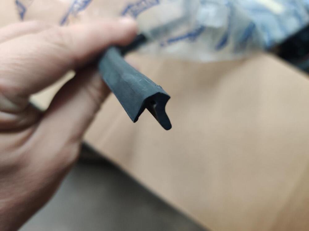
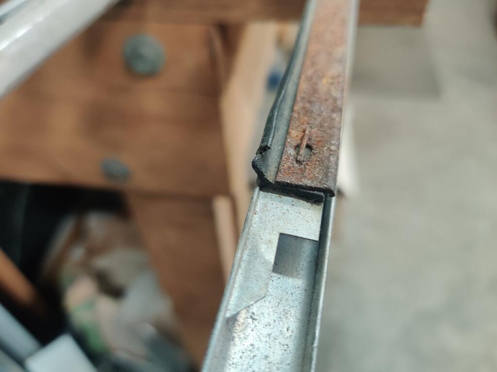
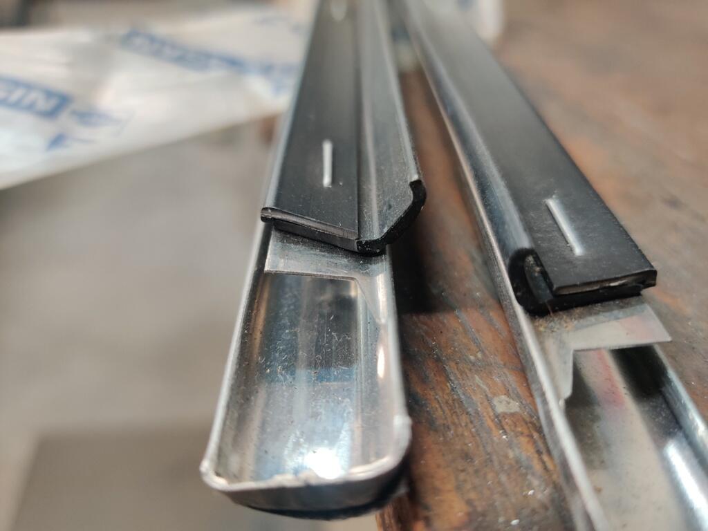
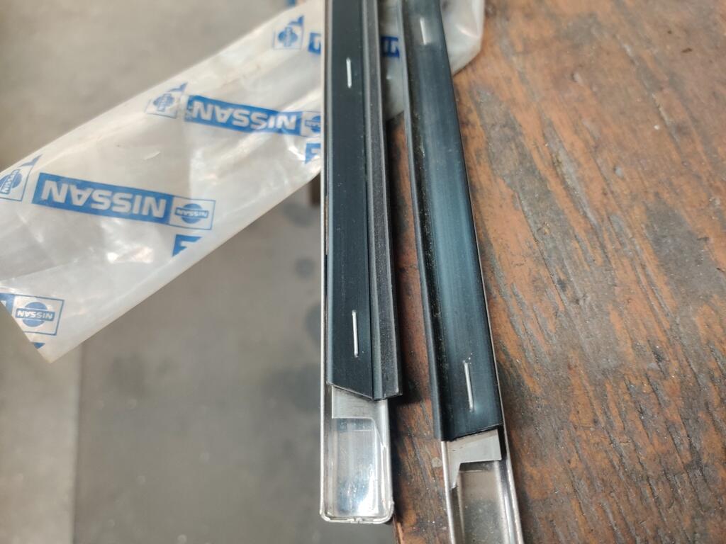
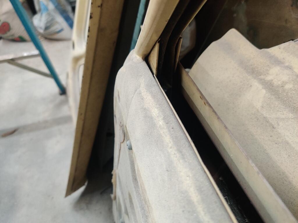
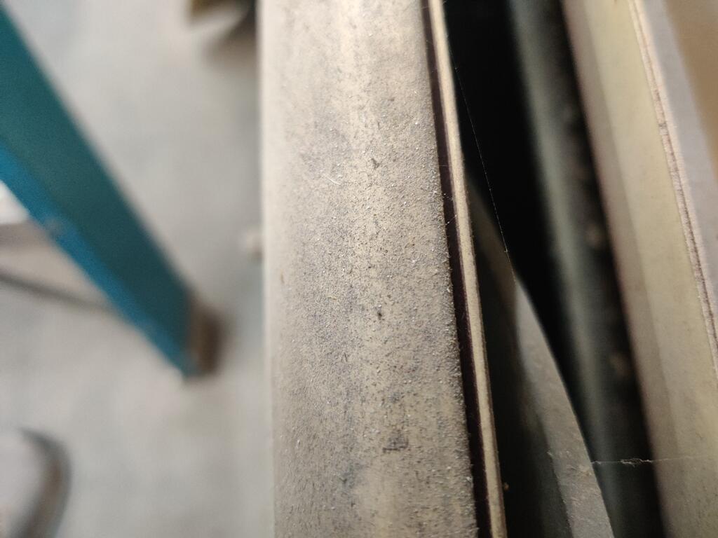
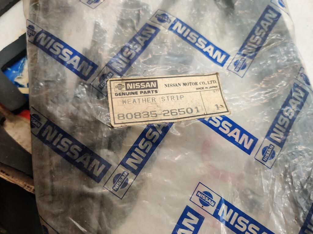
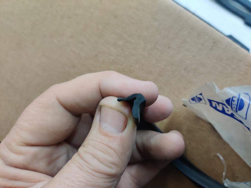
 The first two pics are some 510 4 door outer door/window trim pieces. The second two are 510 2 door outer door/window trim pieces. The rubber looks to be the same shape to me for each of them. The next two pics show the groove on the inside top edge of the door where the inner rubber w/s goes. It is a simple u channel. The last three pictures are of NOS inner rubber weather strips for the 2 door. The front and rear doors of the wagon should use the same inner and outer w/s from a design standpoint, right?


 Looks like I have mostly parts candidates in the hoard. None of then work smoothly.
 Weak chatbot? Where are the emojis?
 For the BEST rubber in your Datsun door..... simply use.. Rubbers - S30 World
That is true, but it could have been converted from auto. I'm just throwing out bread crumbs. Something is drawing too much current. Find the thing.
For the BEST rubber in your Datsun door..... simply use.. Rubbers - S30 World
That is true, but it could have been converted from auto. I'm just throwing out bread crumbs. Something is drawing too much current. Find the thing. Just posted today on eBay. Make an offer? eBayDatsun 240Z 3 Screw Round-top Carburetors, W/ E46 Manifol...Nissan Datsun 240Z Hitachi 3 Screw Round Top Carburetors, E46 Manifold, with Air cleaner. This set up was removed from a wrecked 240Z. These partshave been sitting unused for a while so will obviously


Important Information
By using this site, you agree to our Privacy Policy and Guidelines. We have placed cookies on your device to help make this website better. You can adjust your cookie settings, otherwise we'll assume you're okay to continue.