Leaderboard
-

wheee!
Free Member6Points4,607Posts -
dmorales-bello
Free Member6Points627Posts -
JDMjunkies.ch
Free Member5Points637Posts -

7tooZ
Free Member3Points1,038Posts


Popular Content
Showing content with the highest reputation on 02/14/2020 in all areas
-
3 pointsThanks Chas. I'm not looking for praise or "fishing for likes" as such. I know I am doing a good job, but the difference is that someone with better skills and equipment would have been able to reduce the amount of filler being used or replaced the panels completely. I am running out of a) time b) money c) patience with finishing this build. I am in wayyyyy deeper than I ever expected. In the end I know the car will have flaws, but they will be ones that I know about. Ones that tell a story of how decisions were made, whether good or bad. I suppose I am tempering peoples expectations of the finished product; showing the flaws and warts along the way so the build is not a "fluff story of perfect fabrication"! People tend to post pictures of their success versus their failures lol! In the end, if the car is an 8/10, I will be happy.3 points
-
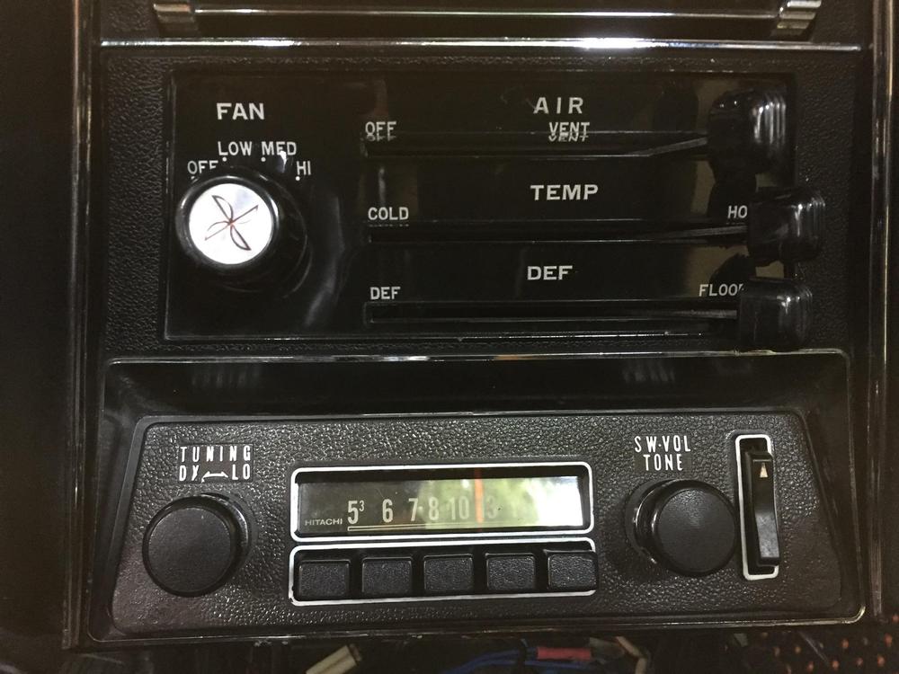
Thought I would weigh in here. Here is my stock looking radio. It was converted to a FMR-2 Aurora. I have made this conversion on this radio and a 62 Corvette Wonder Bar. no one has discover any change yet. AmFm seek still work including the tuning light. However it also has a 40W 4 channel output. Plus an AUX input that plugs into my XR iPhone hidden in the center console. Blue is a option also if want to drive and visit, but not for me. See more info at Joesclassiccarradio.com Just another way to enjoy a classic driver. “Drive a Classic”
 3 points
 -
Your work might save some future wiring harnesses if people follow it. If somebody had time, and a pile of fusible links, and a power source, they could probably define an approximate equivalent, fusible link to maxi-fuse. Just for fun. But if you don't need the excess amperage, it makes no sense to have a higher rating.2 points
-
Thanks a lot for your insight and pictures on this. very interresting with the two versions, Patches, etc. Will definitely have to investigate a bit further on this topic. Haha yeah they are definitely self tapping screws for holding the metals together temporary. Rivets will only be used where there were rivets from factory side...2 points
-
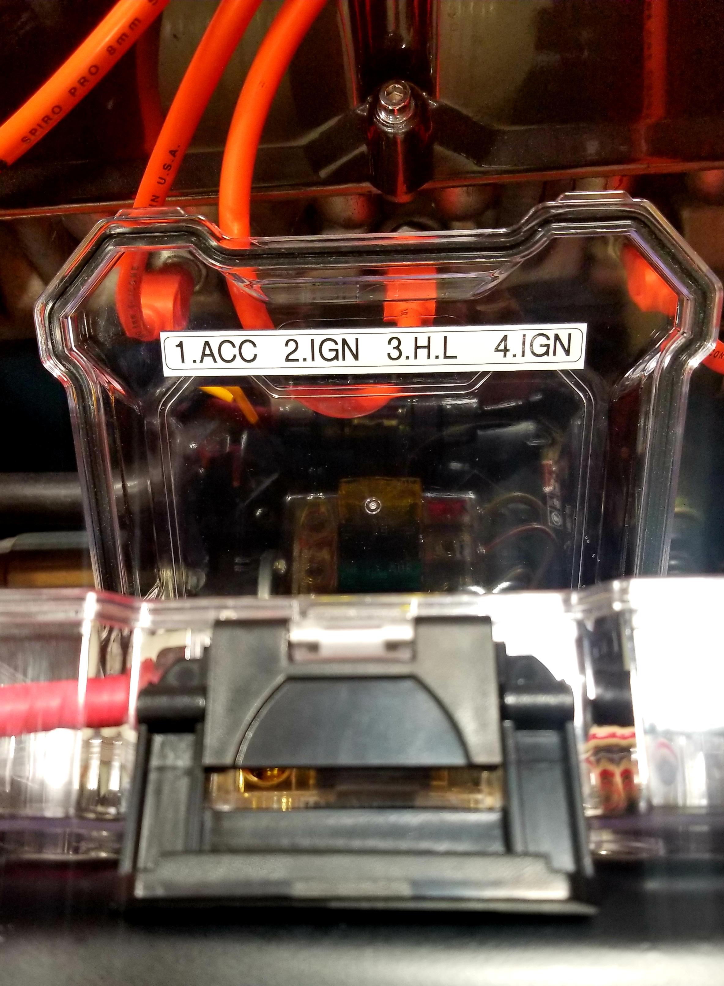
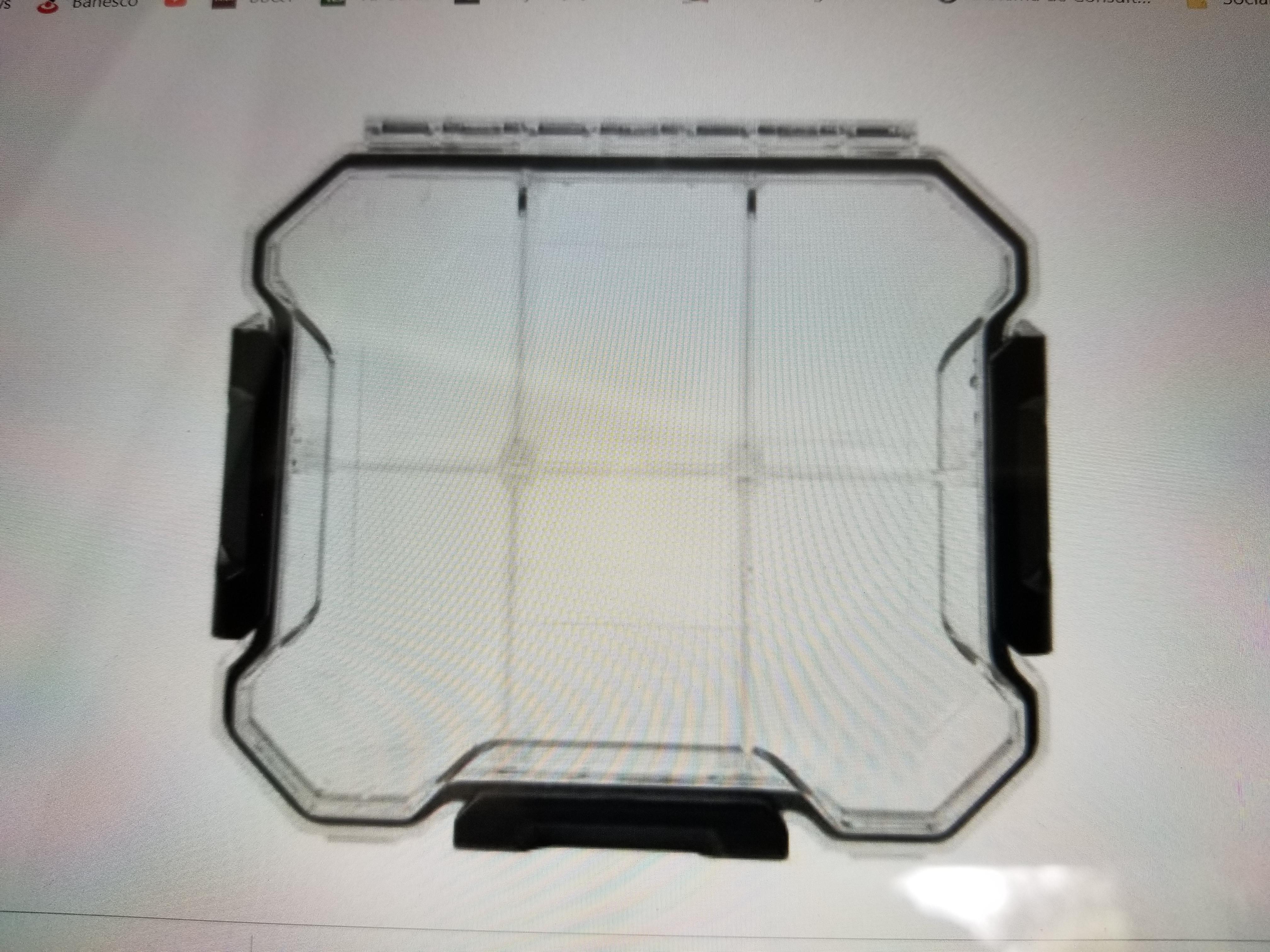
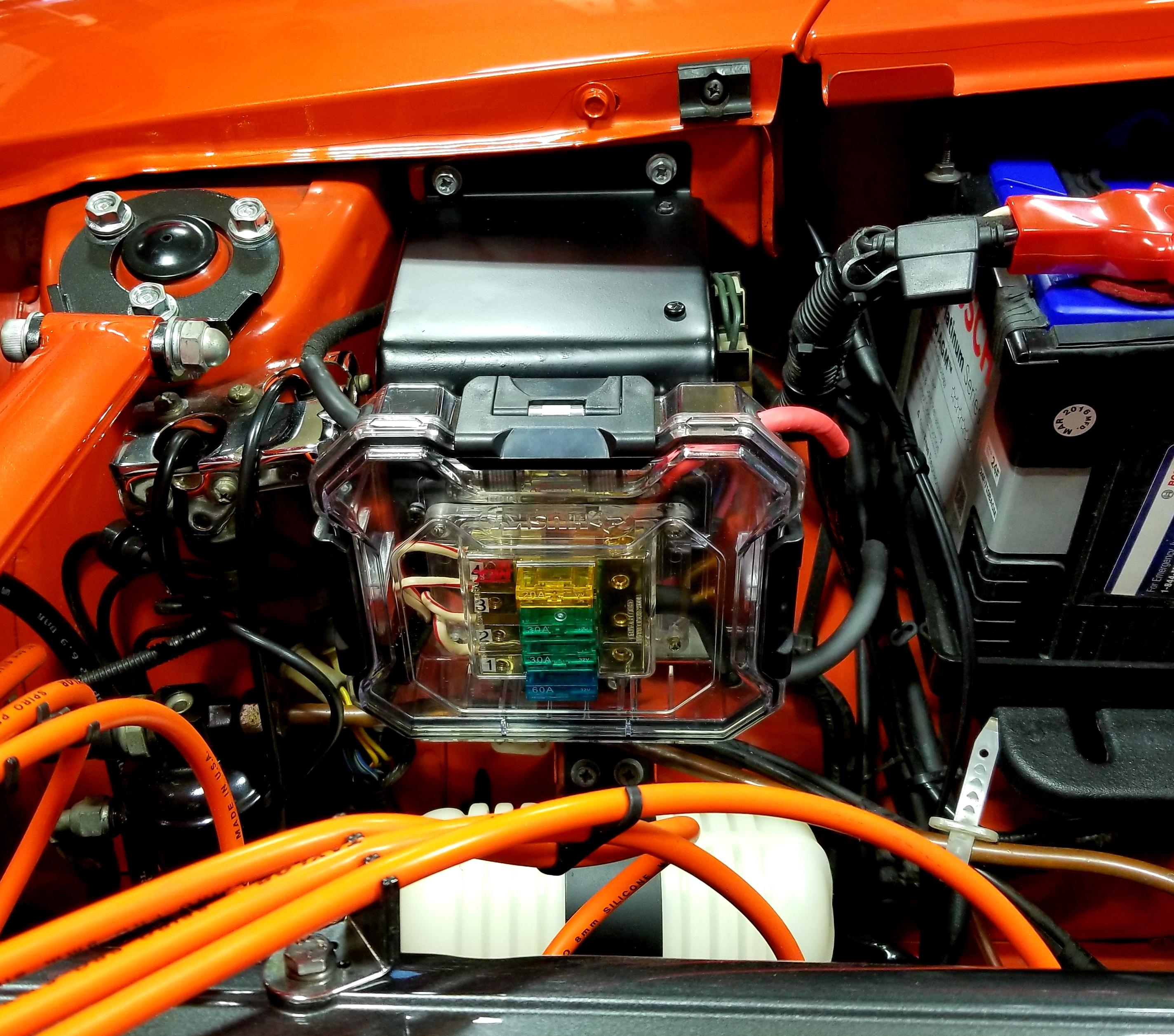
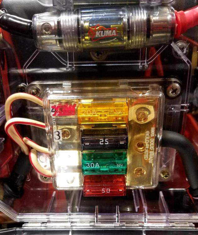
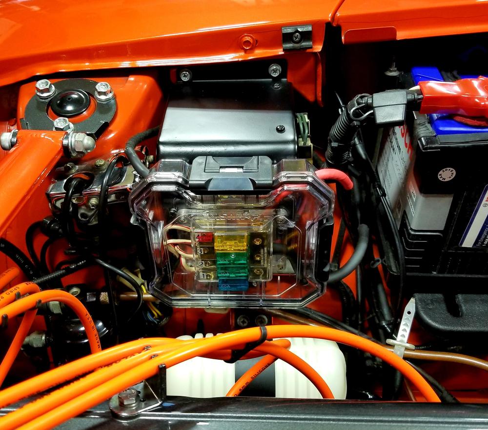
Sure! Here's a couple more. I placed the fuse block inside a watertight acrylic case at the same position in the engine bay where the fusible links were located. I posted a little write up on it a couple of months ago. Sent from my SM-N950U using Tapatalk2 points
-
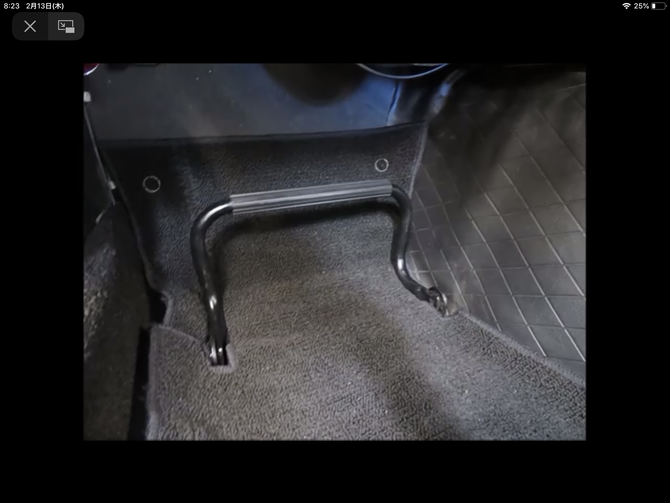
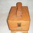
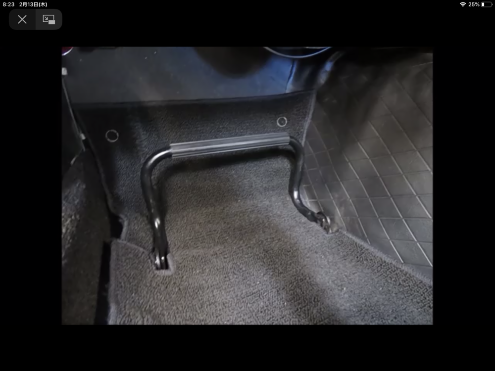
Hi Ian , you are very accurate about the detail of the foot rest , yes the one in Yahoo auction is the correct for the Fairlady Z from the beginning (Oct 1969 ) to 1973 or later . scotta , also a good observation about the reinforcement for the foot rest , early Fairlady Z series ( unknown time period) doesn’t have the patch on the floor. Please see my silver 01/1970 Z432 , there is no reinforcement on the floor (I put a big washer to prevent the floor from being bent , that is not original) . My 06/1972 Fairlady 240ZG has reinforcement patches . Kats

 2 points
 -
This guy has it figured out. I am the same way. That is why I would NEVER consider converting my analog clock to quartz. I even notice (and remember from my youth in 1979), the sound of that loud clock ticking right before I turn the key.2 points
-
Well it depends on what you want from your car - at the end of the day it’s YOUR car!! I vexed about this one for some time then slapped myself and went back to reality where I painfully gutted it and replaced the internals such that every switch and button works but with modern internals. The fact is, I don’t run original tyres, brake pads / discs, I have non-flat top carbs, non-original colour / wheels, non factory exhaust, non-stock alternator or distributor, H4 headlamps, poly bushing, stainless steel bumpers, unleaded fuel ... and the list goes on. But what I do want from my car is to drive the way I enjoy driving it, to be what I demand of it and for the stereo to function properly. That means picking up radio stations I actually want to hear, connecting to my iPhone and playing my music, acting as a hands free kit when I get a call and having enough power to be heard over that glorious straight six warble and entertain me when on the motorway while sitting at 70 in 5th being bored. On the last trip to Silverstone 50th I sat in traffic for well over 3 hours not moving very quickly and participated in a conference call for two hours + some classic period correct 70’s disco [emoji41] for the rest of the time - until we hit the decent roads and turned it all off to enjoy the real soundtrack. As an old school electronic engineer, it pained me greatly to to destroy the beautifully crafted interior of that radio but what I wanted was a fully functional, decent sounding piece of kit that is more than nostalgia in function yet looks totally original when not in use. However if I had a concourse, fully stock Z, then I’d keep everything original any day.2 points
-
I think they are rare outside Japan. I have had a few come through my hands, and there is slight differences between them, about 5 or 6. As you see yours has both "feet" facing the same way, and the bottom of the feet are square. https://page.auctions.yahoo.co.jp/jp/auction/g375566873 As you see, the "feet" face each other, and bottom of the feet are rounded. There is also differences in the bolts to fix the footrest to the car, some are round headed like yours, some are slotted head. And the rivet holding the hoop and the feet differs too. If you blast it, cover the ribbed rubber bit, as these aren't avaliable, I had to reproduce it for my footrests.2 points
-
1 pointMark, Re: Flaws...When Navajo women weave their beautiful blankets they purposely put in a "flaw" to let any evil spirits out. Now you know that there will be NO evil spirits in your amazing build. Can't wait to see and hear this incredible project get "completed". Cheers, Mike1 point
-
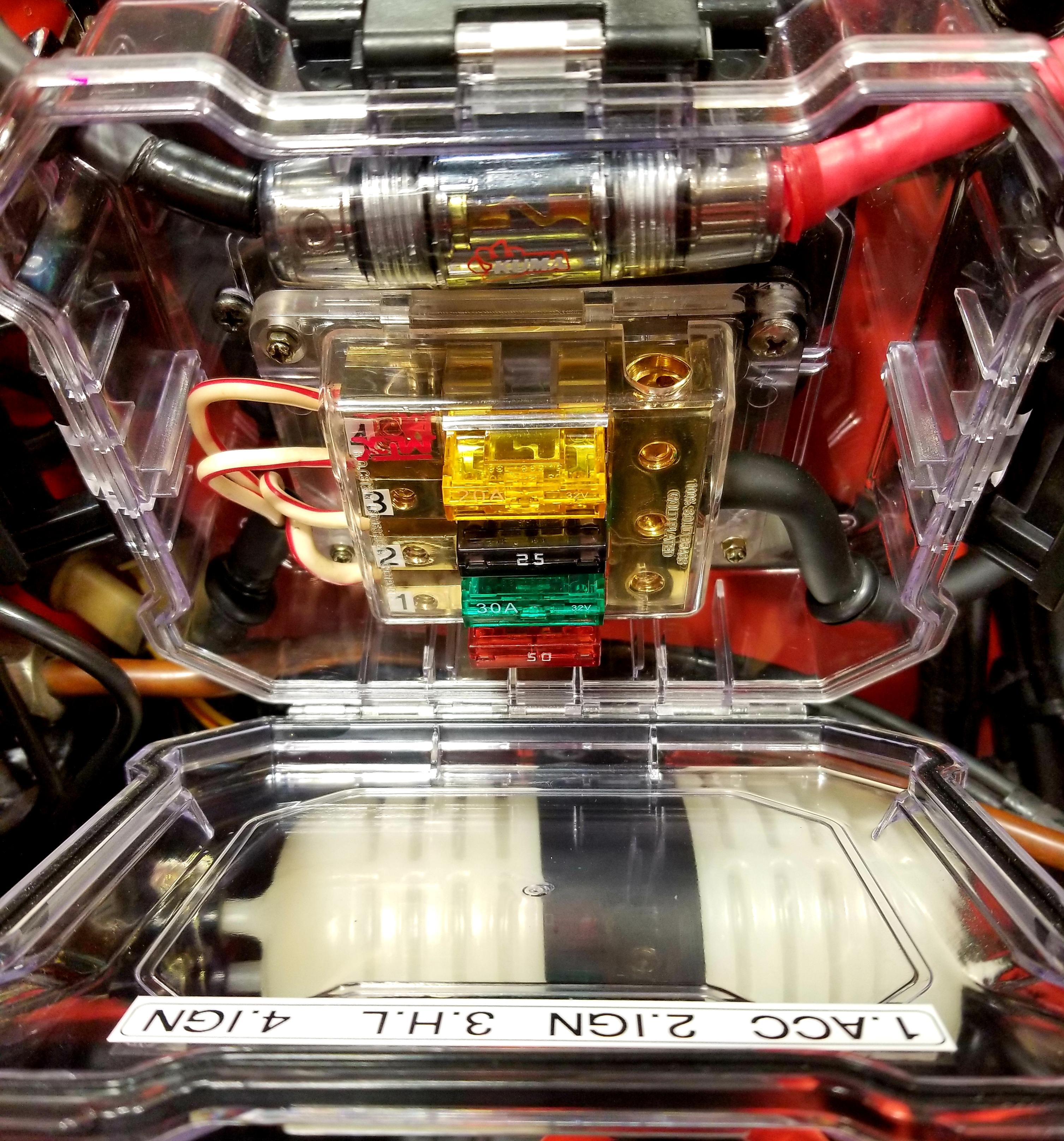
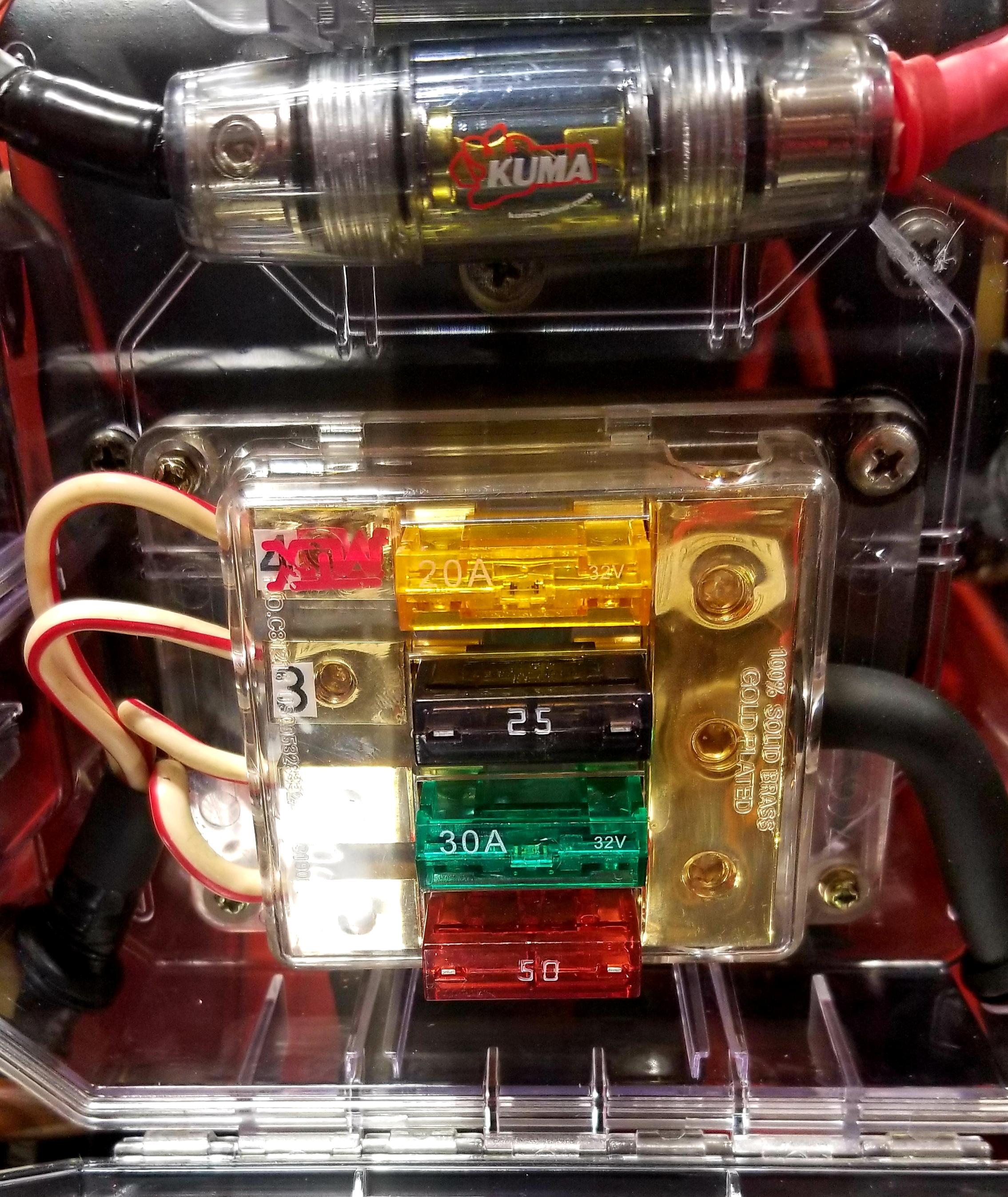
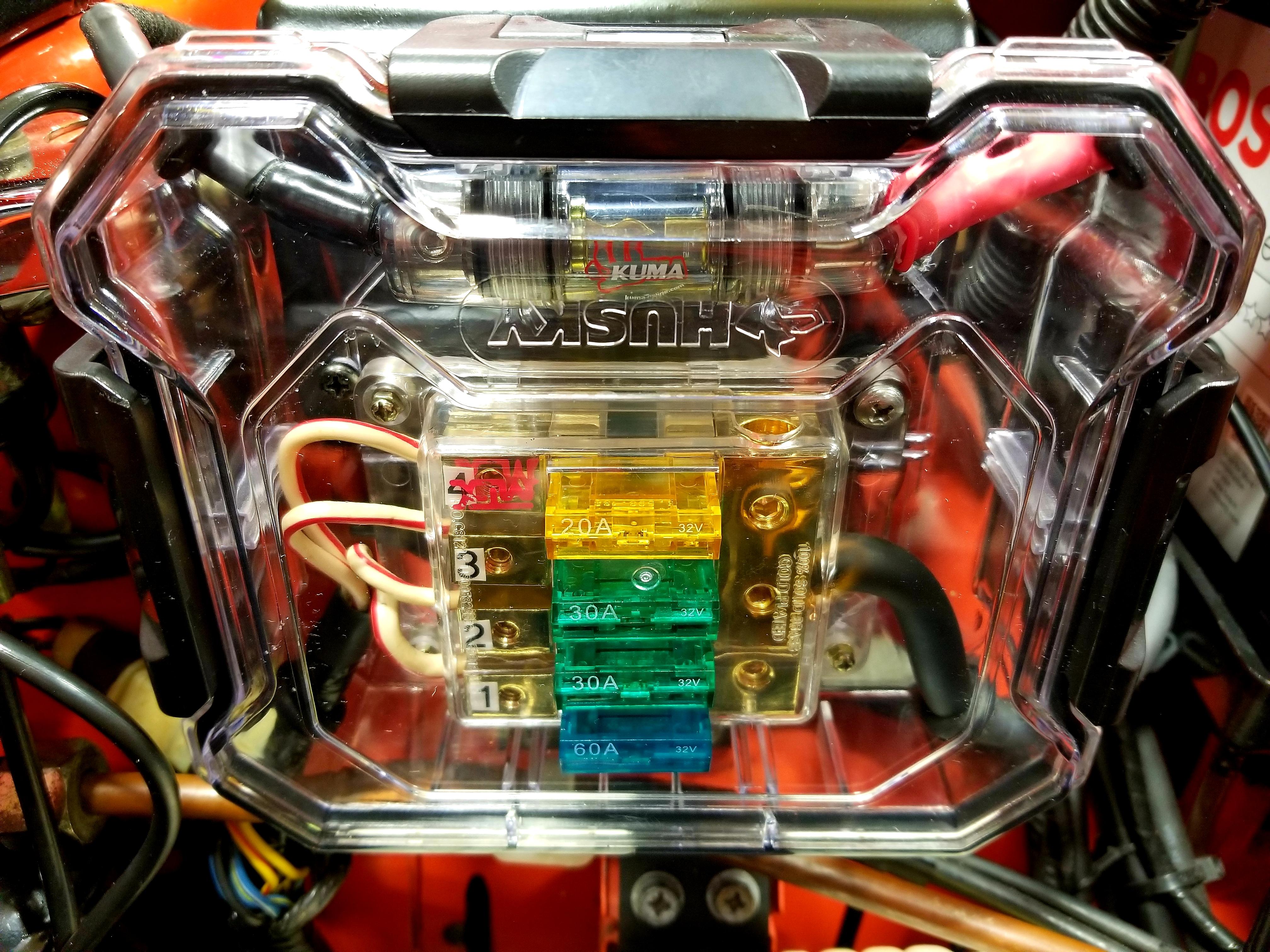
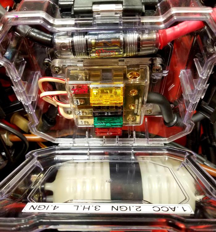
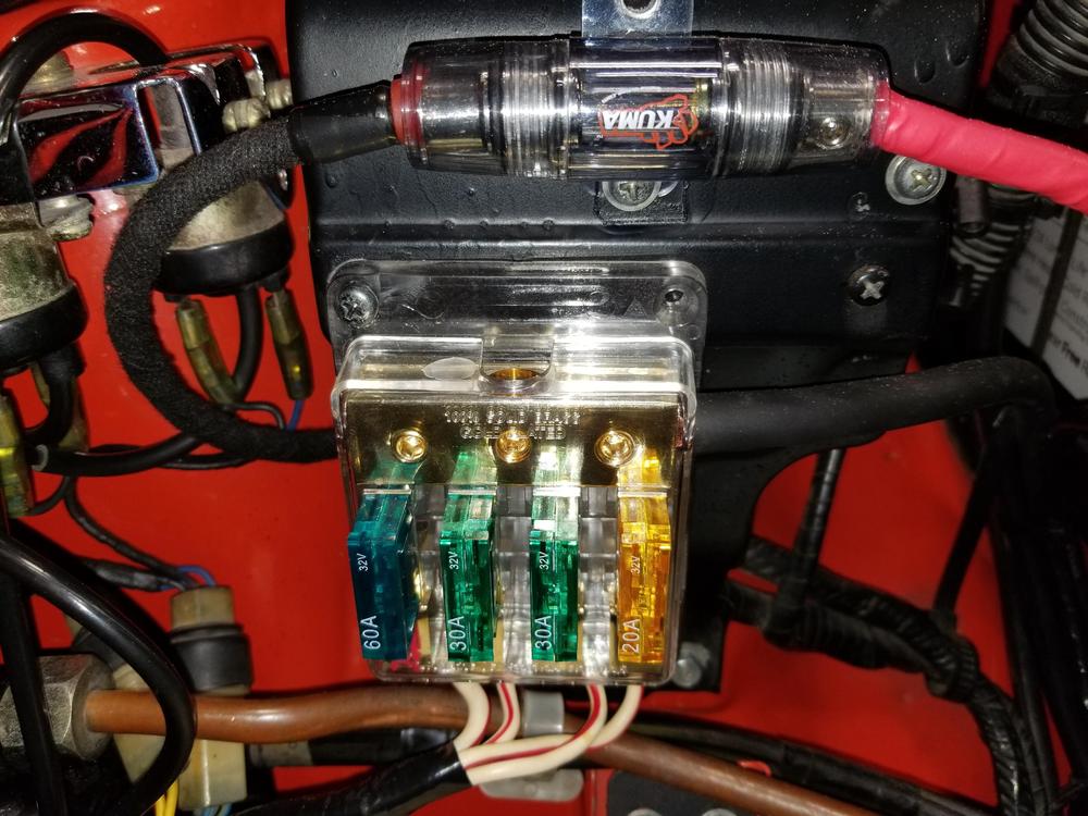
I was committed to updating the information pertaining the amp rating for the Maxifuses I used in the fuse block that replaced the fusible links but I'm embarrassed to admit I can't locate that post. Moderator's help in properly placing this update will be appreciated. Anyhow, here's the update. I have been running this set-up (pics below) for a couple of months without issues. The consensus was to decrease the amp rating of the fuses used as much as was logically possible to test how well they protected each circuit. I've made a point of driving with as much electrical draw as possible with the AC, headlights, sound system, turn signals when necessary, hazard lights and horn when possible. The only system I haven't used simultaneously is the windshield wipers/washer because I don't take the car out in the rain. The circuits have been identified on the decal on the inside of the case cover. Despite the information on the Atlantic Z page regarding amp ratings for the different color fusible links, my current (no pun intended) set-up is much lower and, as stated previously, seems to be working well. Circuit 1 (ACC): 50 amps, Circuit 2 (IGN): 30 amps, Circuit 3 (H.L.) 25 amps, Circuit 4 (IGN) 20 amps

 1 point
 -
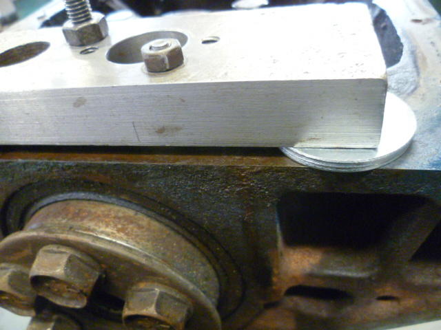
1 pointMy build buddy hit the PCV screen holder screws with an impact and said they came out easy-peasy. Thanks for the info guys. On another topic, this was my experience pulling that troublesome rear main bearing cap. I made this little puller adapter contraption from a scrap parts I had laying around. Riddled with extra holes from previous fixturing and holding uses. Anyway, couple holes and some threaded rod: Put it on the rear main cap and run the three threaded parts down into the holes in the cap. The two smaller threaded parts get threaded into the oil pan mounting holes while the larger part goes into the other threaded hole in the cap. Put a couple washers under the puller as jacking points and then run the nuts down against the puller to lift the cap out. It's not pretty (or symmetric), but it's what I had laying around. When you run the nuts down, it pulls the cap out a little. Keep stacking washers and repeating the process until you have the cap off: The FSM uses just the one larger threaded hole, but I found the bearing cap tends to cokk sideways as you pull it. I found I could keep the cap even and pull much straighter out if I used the oil pan mounting bolts as well as just the traditional puller hole.


 1 point
 -
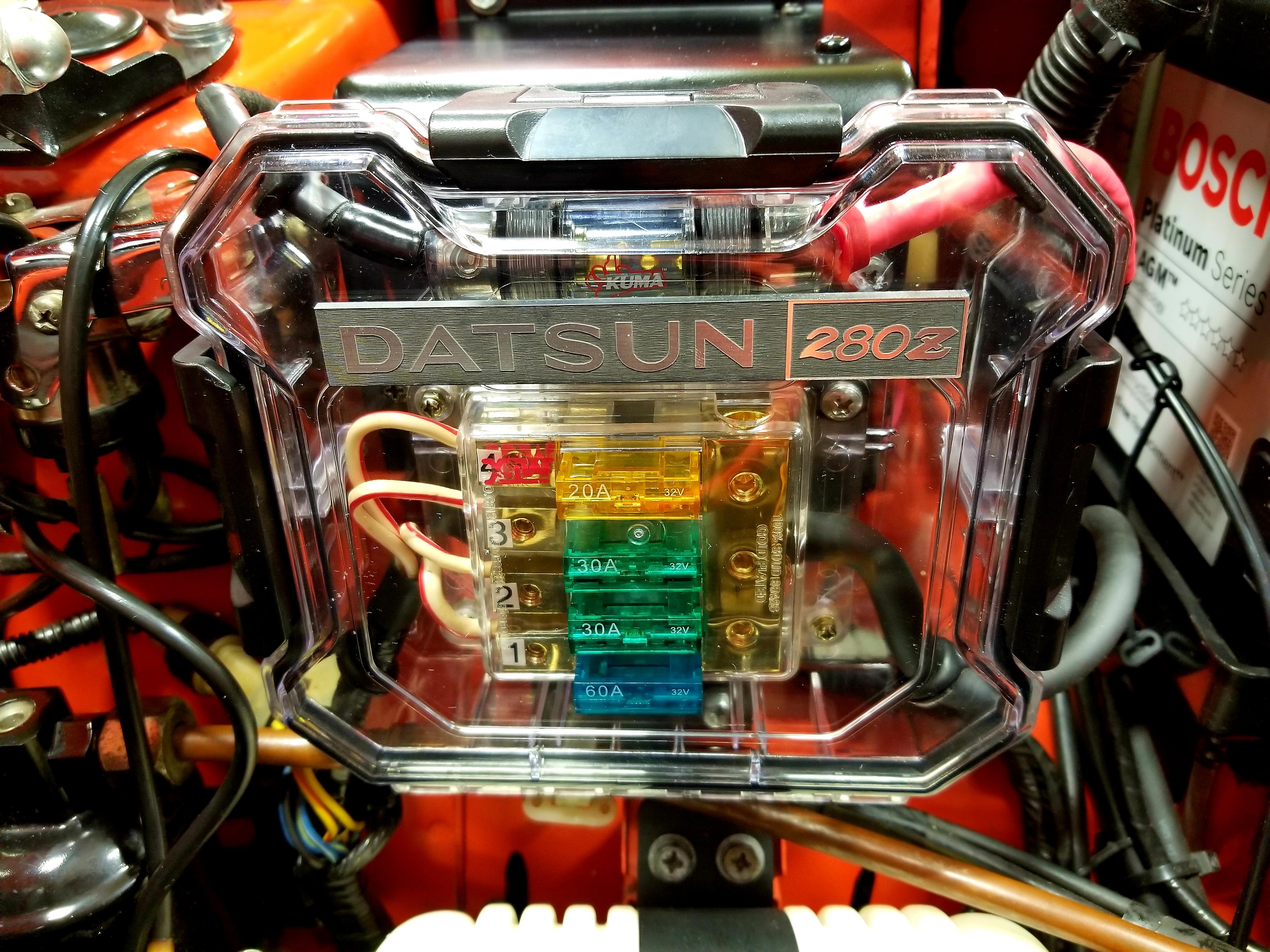
I just realized the cause of your confusion is that the pics are out of sequence. My bad, sorry. The pic with the 30 amp fuse is older and the one with the 25 amp fuse is the newer with my current set-up. Sent from my SM-N950U using Tapatalk1 point
-
No, the 30 amp fuse held up fine but the idea is to find the lowest rating fuse that will still protect the circuit in case of a short, that way your cables won't fry before your fuse blows. I actually started with a 50 amp fuse in that circuit and have been working my way down to 25 amps which is likely where I'll stop as long as it holds under all normal loads. Sent from my SM-N950U using Tapatalk1 point
-
ah the sound of the ticking indeed! I just like the feel of the push buttons. I did comprise some, I put in a second speaker (in the unused location) and popped for a later model Hitachi that had stereo, I am not a barbarian after all.1 point
-
1 point
-
1 pointI have some rockers and some other stuff if you know anyone needs it . I’m ready to just give this stuff away because I want someone to use it .1 point
-
Update: Got it out with Dave's help. For those who want to know you put the housing in a vice and tap on the rod end gently and it will push the plug out undamaged and can be re-seated afterwords.1 point
-
1 point
-
1 point
-
Oh I think you are right! My faith in his bodyman has been restored? I just saw how shiny they were and assumed they aluminum rivets, using zip screws is exactly how I do it too. Need new glasses.1 point
-
Are you sure they're rivets? I thought they were self tapping screws for temporary purposes1 point
-
Passenger footrest was standard equipment on 'DELUXE' models in Japan, and an extra-cost showroom order option on 'STANDARD' models.1 point
-
The foot rests were standard items on JDM cars. My 1972, FZ-L has it. Note that the floor has reinforcing where it bolts through.
 1 point
 -
Here are a couple of old threads discussing early hoods, with pictures of the two early and later types.1 point
-
1 pointThank you for your service Mike. Your generation inspired mine to serve in your honour and footsteps. My combat tour with the Taliban in panjwaii will never compare to the hardship and loss you endured in Vietnam. I lived in a concrete bunker on a reinforced mountain with internet, hot food and showers. Yes we were surrounded by enemy at all times and were attacked daily, but were supplied and defended by incredible modern weapons. As a current Warrant Officer, I remind my troops daily of the sacrifices of previous generations and the current “day care” mentality of the military. Again, hats off to you and your generation.1 point
-
Well yeah, i have yet another two new books to add to my ever evolving list of Z-related books i have to read and translate when i find some time. 1) Fairlady Z Story and history, Vol. 1 - The 50th Anniversary Chronicles. A book about the history of the Z including the development It contains some backgroundinformation. for example about road testing in America: And some of the racing cars. I've just been flicking through it yet, but it seems it seems to focus on the car globally with pictures showing old woking station, american race cars but also the japanese. so this might be an interessteing one ? 2) Japanese masterpiece series [Vol.12] - Nissan Fairlady This book is actually a bit older (released in August 1973). The cool thing is, it contains some backgronud information but also a lot of nice drawings and technical information about the different version. as shown below. Still have to read it as well, but they seem to be (aside from the factory books) some of the more promising and serious books i bought. But i still have to prove my initial feelings about them ?1 point
-
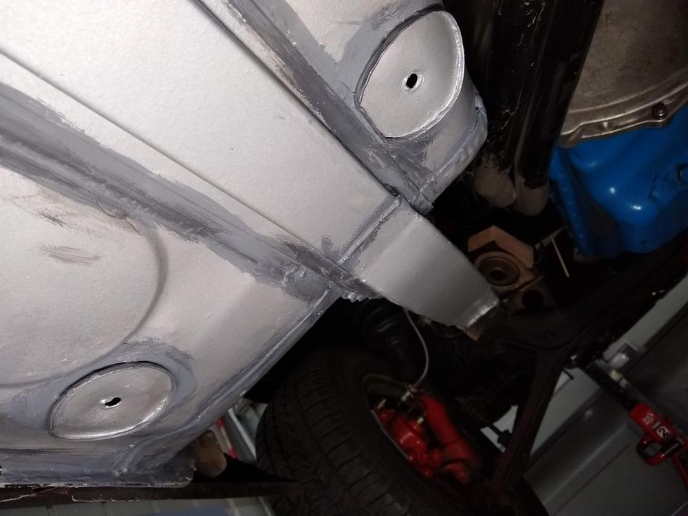
So, My panelbeater started work on the passenger side floors. Those hungarian-made floor pans came in.. before: After: Still have to be welded etc. but overall fitment looks nice. Here is the bottom side fitment together with the NOS frame rails. Seems pretty spot-on!1 point
-
Finally, a lifsign from the bodyshop. Nothing big. but the little update came along a promise that he will contune work on the car again soon. which makes me quite a bit happy. Today he got the brackets for the rear bumper sandblasted, so i assume the plan is to get the rear valance welded back on the car soon:1 point
-
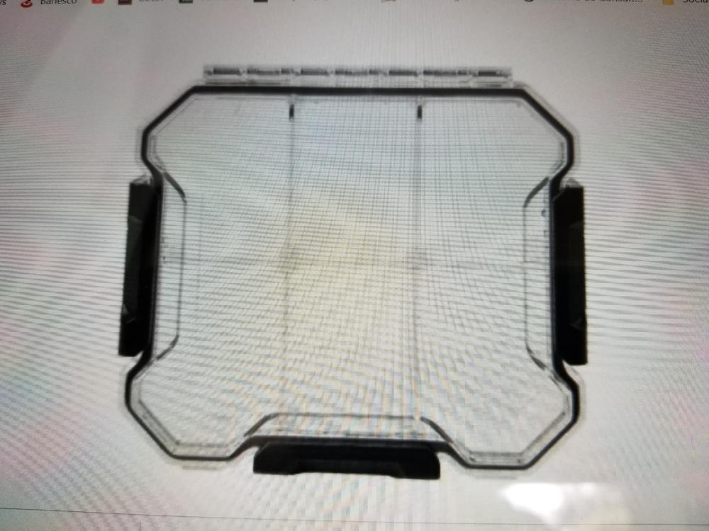
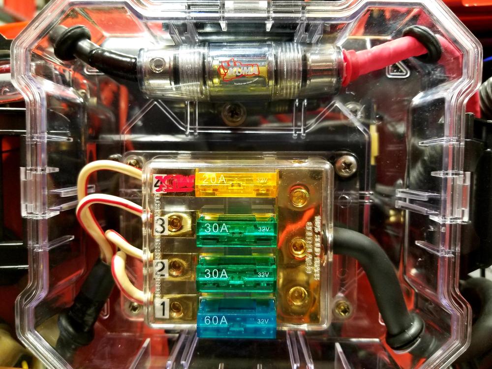
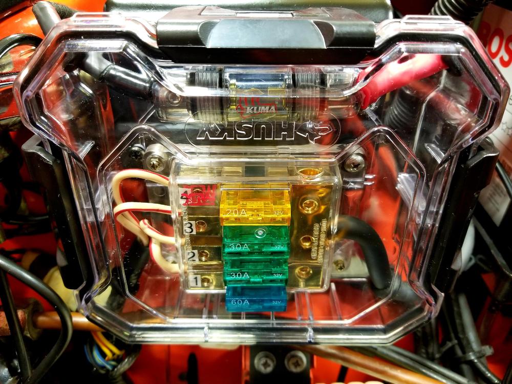
1 pointI've been running my Maxifuse 4 circuit fuse block for a few months (replacement for the old fusible link set up) and all the electricals are working well. My worry has been the fact that the set up is definitely not water resistant (much less water proof) which could be a huge problem if I get caught in rain or simply carelessly wash my car. I like the fact that it's a simple 4 circuit system with readily available fuses so I found a way to put it inside a Husky brand (Home Depot) WATERPROOF 6" small parts box ( measures exactly 6"x6"x2") made of hard clear plastic. It looks like acrylic but I'm not sure. I pulled out all the partitions, opened 4 holes (one in each angled corner) and fit them with rubber grommets for all the input and output cables. Fixed the fuse block inside with well nuts placed on the bottom of the case (as well as the sound system fuse holder) and attached the set up back again in place of the old fusible link holders. Oh yeah, and I covered up the inverted "husky" logo with a spare 3D printed 280Z logo I had laying around. All the electricals tested well. I will run this for a while to test the durability of the clear plastic but I think it'll fare very well considering the fuse block itself was exposed to the heat of the engine bay for months without issue and this plastic seems very similar to that. I'll report long term findings if any. Pics below.

 1 point