Leaderboard
-
.JPG.cfcada9cf1c1b502df3f5f2f2ca3ff36.JPG)
SteveJ
Free Member7Points9,646Posts -
zclocks
Free Member5Points311Posts -
grannyknot
Free Member4Points5,158Posts -
Patcon
 Subscriber
 3Points11,142Posts


Popular Content
Showing content with the highest reputation on 09/11/2023 in all areas
-
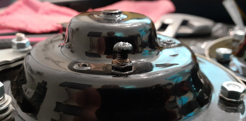
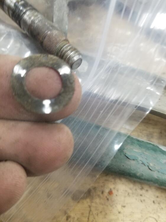
5 pointsI cracked the code on the horns. I was working on getting @Tirnipgreen's re-plated horns working. I tinkered with them some a while back, but I needed some time to focus on them to get the bugs out. Fortunately I had one of my old 260Z horns that was unmolested to use as a template. Before I go into detail, let's talk about the theory of operation. When you press the horn button, the relay sends voltage to the horn. The coil in the horn is energized, pulling the diaphragm in. The bar on the back side of the diaphragm hits a tab on a set of contacts on the negative side of the coil, de-energizing the coil. The diaphragm snaps back into place, allowing the contacts to close. Repeat steps 2 through 4 as long at the horn button is depressed. The vibration of the diaphragm is what makes the sound. So what appear to be the potential failure points? The tab for the positive wire on the outside of the horn loses electrical contact with the coil inside the horn. The contacts get carboned up. The bar on the diaphragm is not aligned properly. The tone screw is not adjusted properly. I don't have a documented fix for #1. You see it by measuring resistance between the outside tab and the inside of the horn where the coil wire is mounted. Ideally, you should have continuity. For #2, test by measuring resistance from the positive side of the coil to the body of the horn. It should be less than 2 ohms. To lower resistance, I cut a 3/4 inch wide strip of 1000 grit sandpaper and folded it in half. I worked it between the contacts and pulled it through a couple of times, using the tab on the contacts to moderate the pressure. I measured resistance from the positive to body of the horn until it dropped to less than 2 ohms. For #3, I took a straight edge and held it against the side of the bar. There are two alignment holes on the diaphragm, and I noted the distance between the straight edge and the hole. It's between 1 and 2 mm. If the bar on the horn you're working on doesn't line up that close, loosen the M6 nut and rotate the bar. Hold it in place carefully while locking now the nut. After adjusting the internals, put the horn back together. Measure resistance from the positive tab to the mounting bracket of the horn. If it's more than 20 Ohms, the tone screw is turned in too much. The tone screw is an M4 screw on the back of the horn. The screw in the photo below was powder coated onto the horn, and I had to break it loose. I got the resistance from being over 1 MOhm to around 2 ohms. After that I used a car battery to test the horn and get a better tone. I had to work the screw in and out a few times until I was happy with the results. 20230910_153848.mp4 The other horn was a little more challenging. When I tried to break the screw loose, the screwdriver chewed up the head. I had to replace it with the only screws I had available, allen head screws. After playing around with the height of the screw, I finally got a decent volume out of it. 20230910_160521.mp4

 5 points
 -
3 pointsYour correct it would be reducing the voltage there by making the transistor turn on harder. The C828 could have different characteristics compared to the replacement values we use today. It could be that the transistor you used needs a slightly higher Base voltage to turn on. I think there was more than one problem here and something isn't right between the 10uF cap on the base of the transistor. Replacing the caps and the transistor usually corrects the problem 90% of the time. If the coil values were off that could be the problem, but they look good. If changing the 2Meg resistor with a slightly lower value doesn't work send the board to me. I have a 280 test mechanism that I know works and that can be eliminated. I have seen problems with the mechanism that don't work like they should and suspect the magnets on the fly wheels have degraded. I can also check the component values and see if they are correct. Ron3 points
-
2 points
-
2 pointsIf you remove " Dish " from dishwasher, you have a parts washer2 points
-
HLS30-07631 on the auction block. Bidding starts at $1.00 with modest reserve. https://www.ebay.com/itm/3948715088062 points
-
I posted more about the horns in this thread: I took some video of the work that I need to edit and post on YouTube.2 points
-
2 points
-
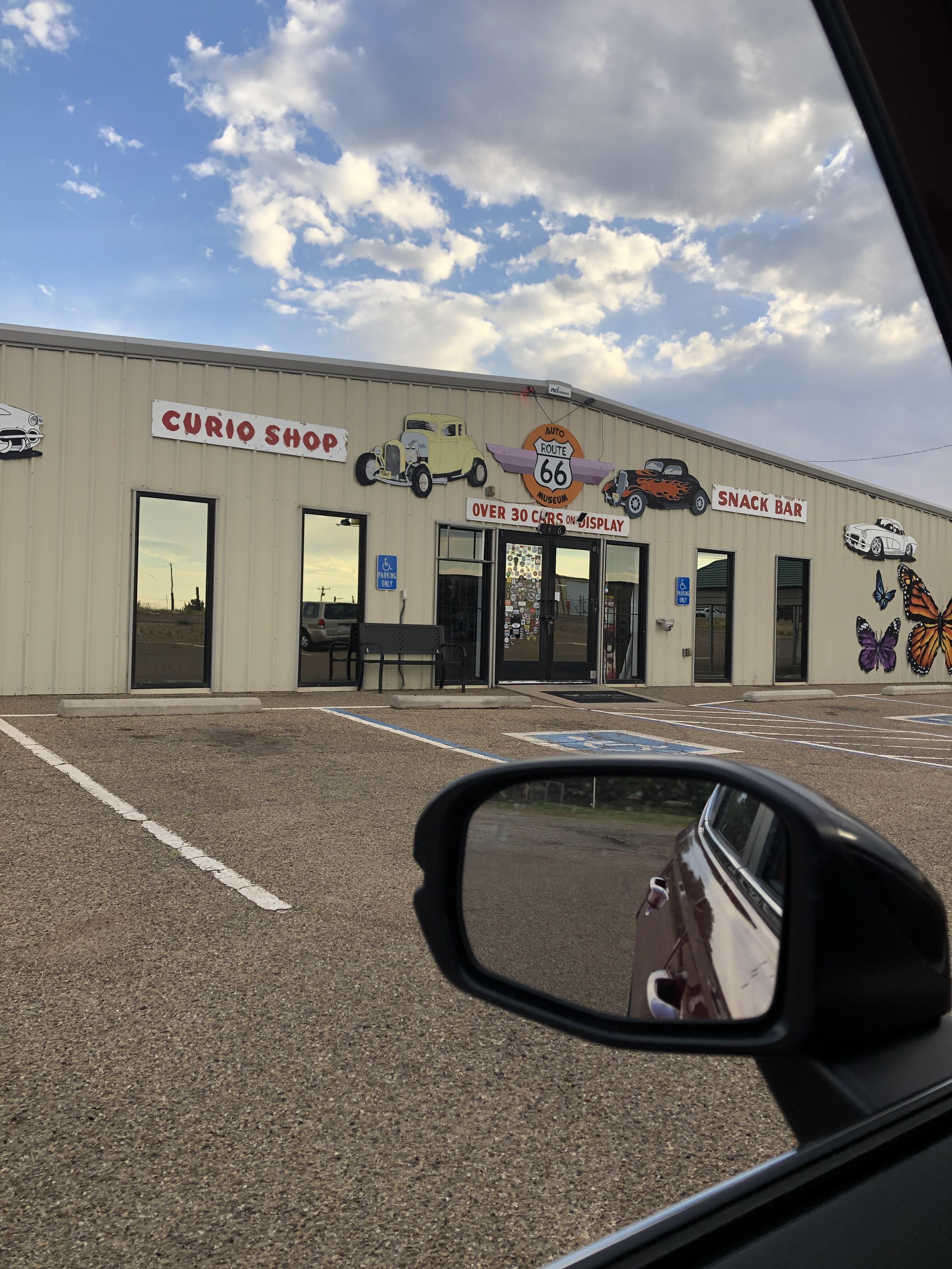
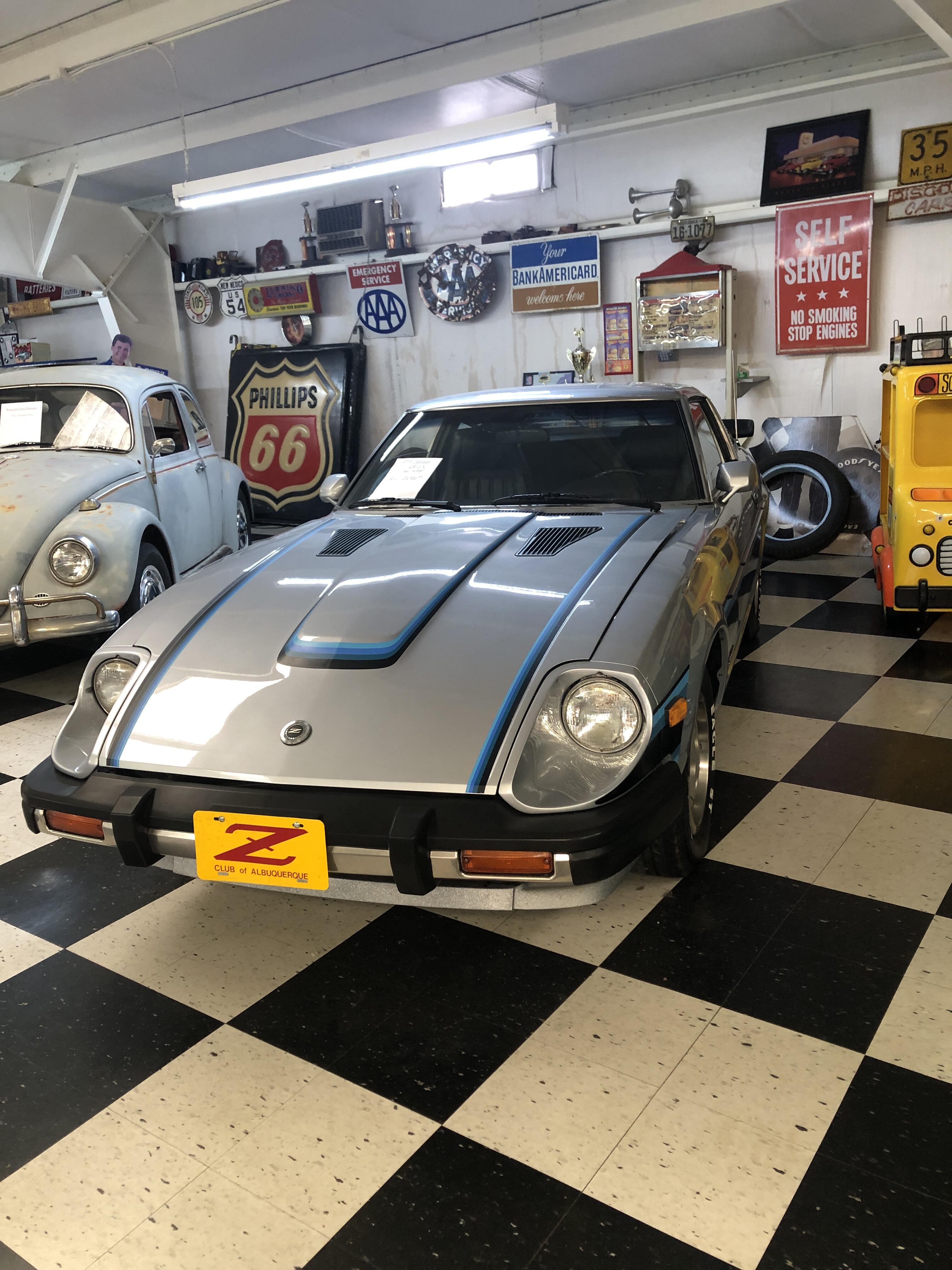
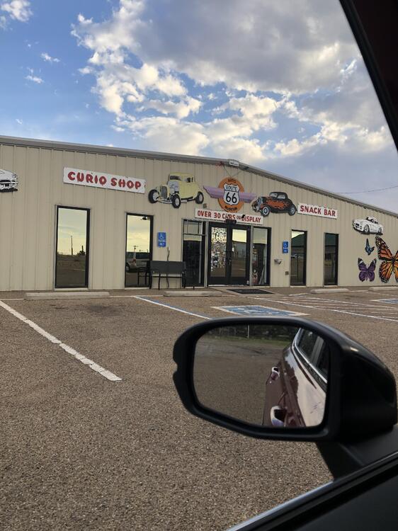
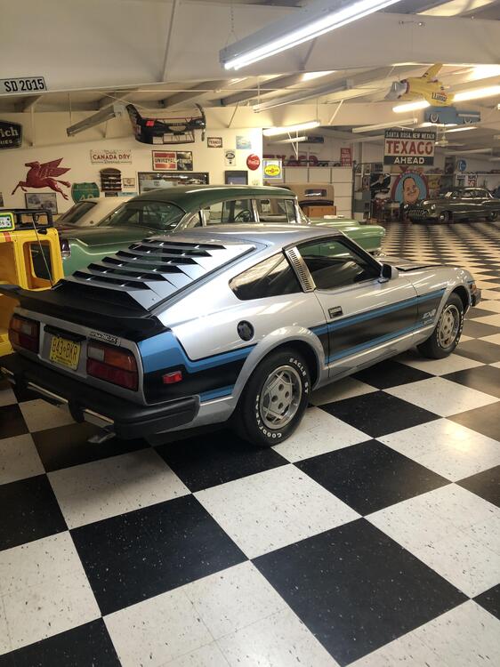
1 pointI just visited the Route 66 Auto Museum in Santa Rosa, NM (Link) and among the collections is a Datsun 280ZXR: Several other non-Datsun cars and one of the largest collection of Route 66 memorabilia I have ever seen!!! Enjoy. Keith

 1 point
 -
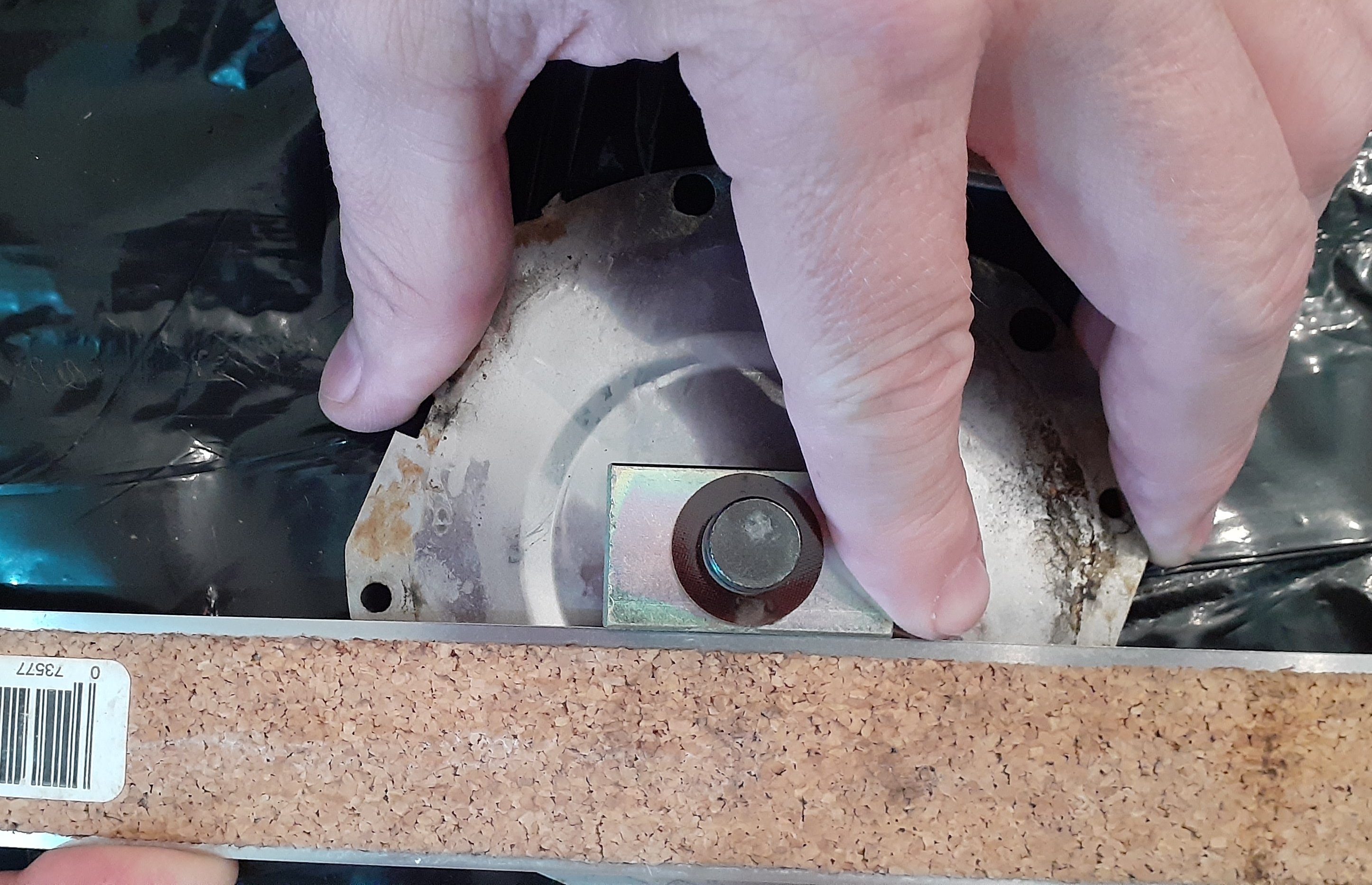
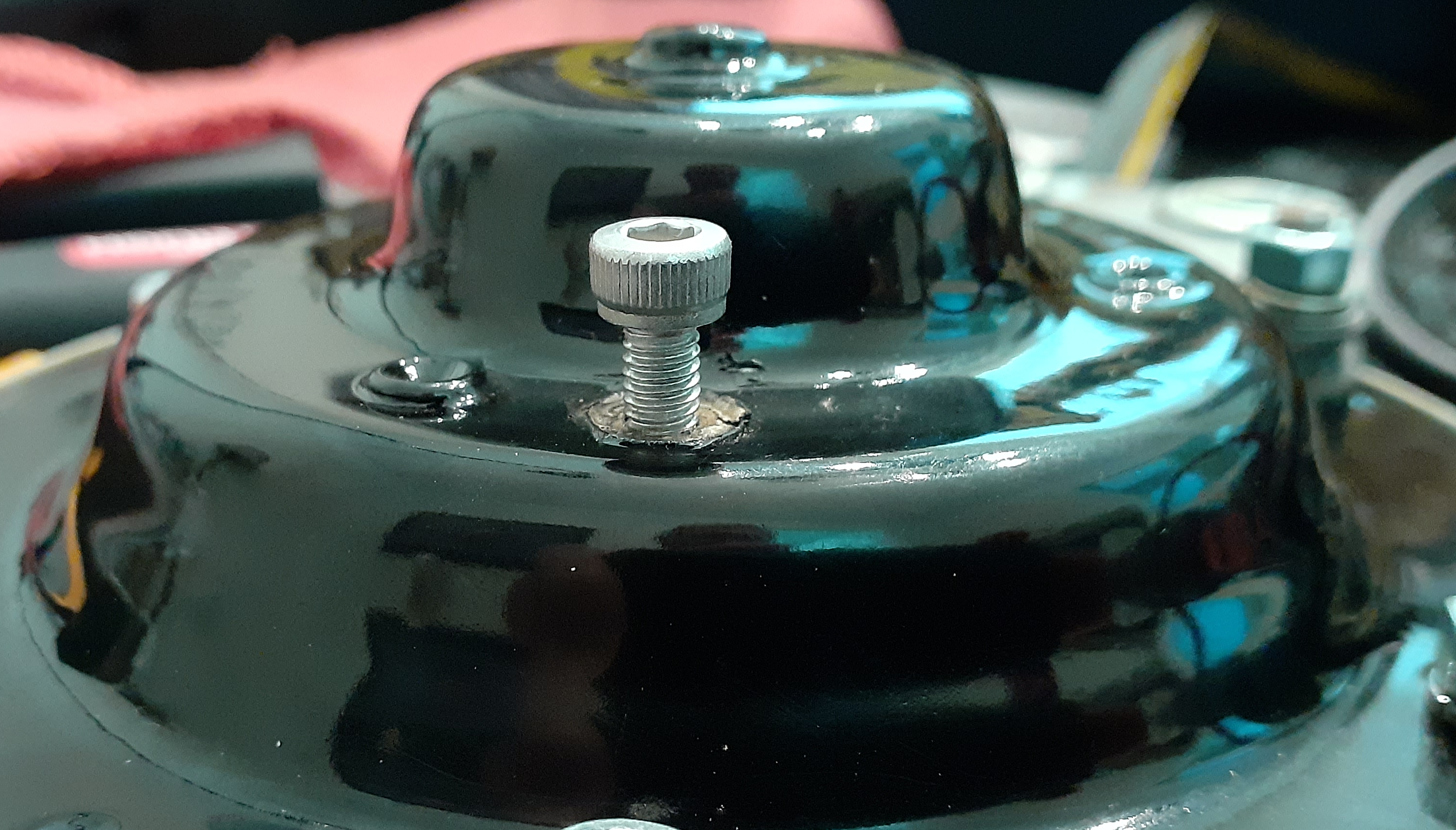
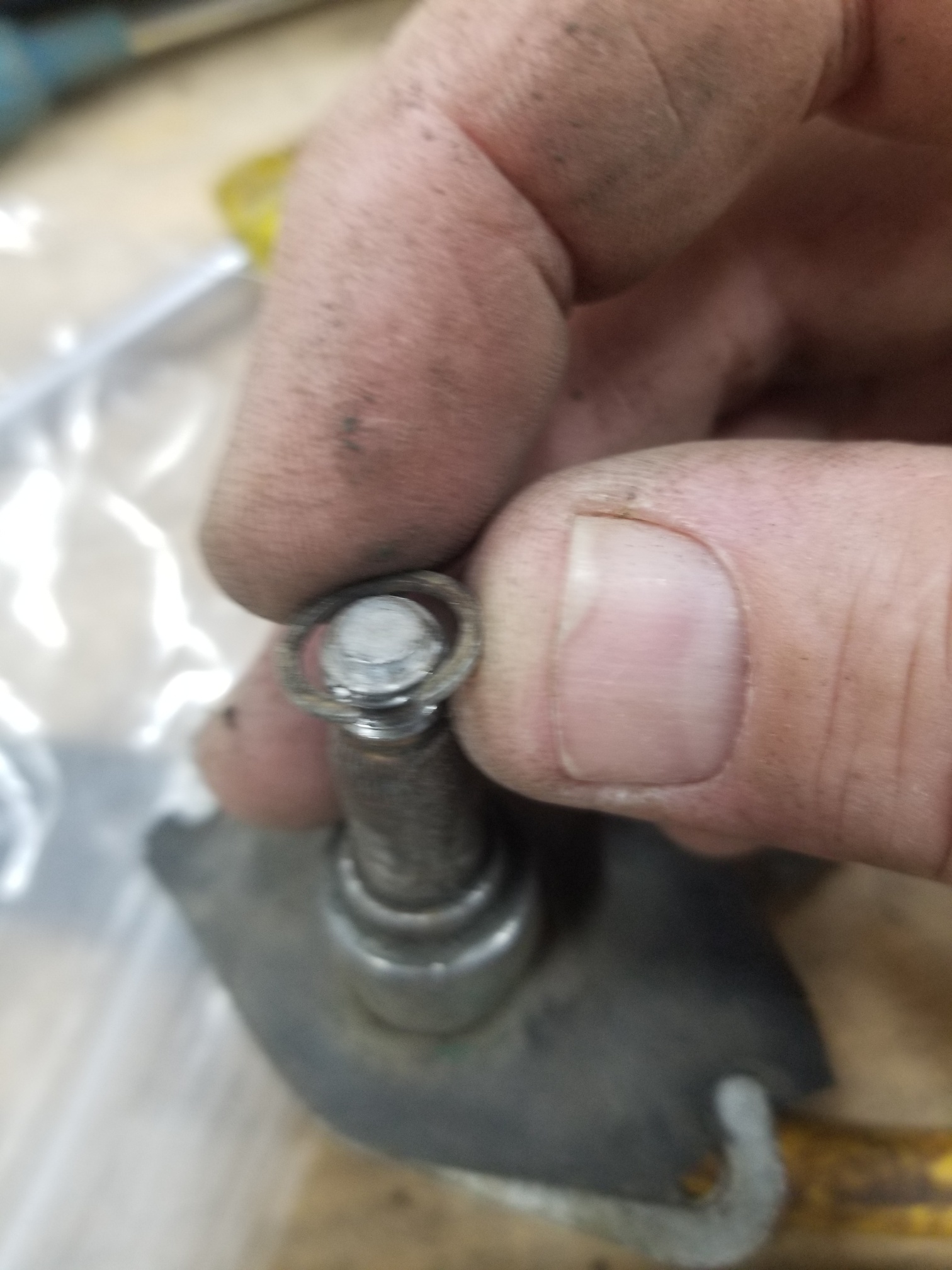
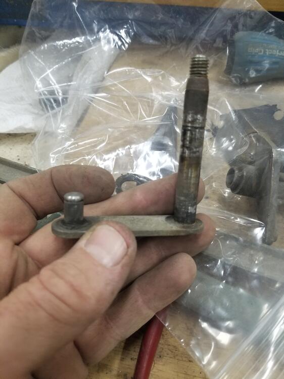
Yes, I've noticed that in the last few years. Sneaky! There were a few other Nissan models that had fairly similar front hub/spindle castings. Some of them probably fit the S30 series too. Is the second half of the part number indeed '16230'? Usually I'd expect an official strut for Nissans of that period to have an alphabet letter at the beginning of the part number suffix which is a great help in identification. I'm guessing that Kayaba/KYB themselves might be helpful in giving you a positive identification? Edited to add: That top mount might also be a clue? Can you post a picture of it from the top? The spring looks to be smaller outer diameter than I'd expect too.1 point
-
That looks like quite a 'late' pair of struts (late 70s/early 80s?), and I don't *think* they were for use on the S30 chassis. I don't recognise the part numbers (54302 indicates RH Front, but is the suffix number '16230'?) and I'm wondering what other chassis they might have been made for. None of the factory adjustable-platform struts for the S30 were externally adjustable in that way.1 point
-
1 point
-
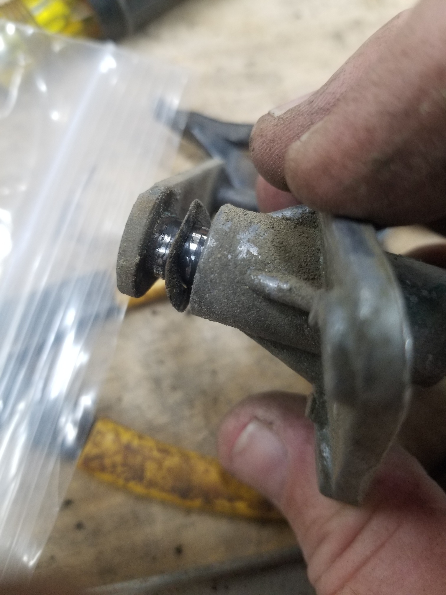
1 pointI think you are right on all counts, I would zinc the whole piece. The cast aluminum triangular body that the spindle spins in has a recess inside, just pack that with hard grease, it will help take up any slack from wear in the spindle.1 point
-
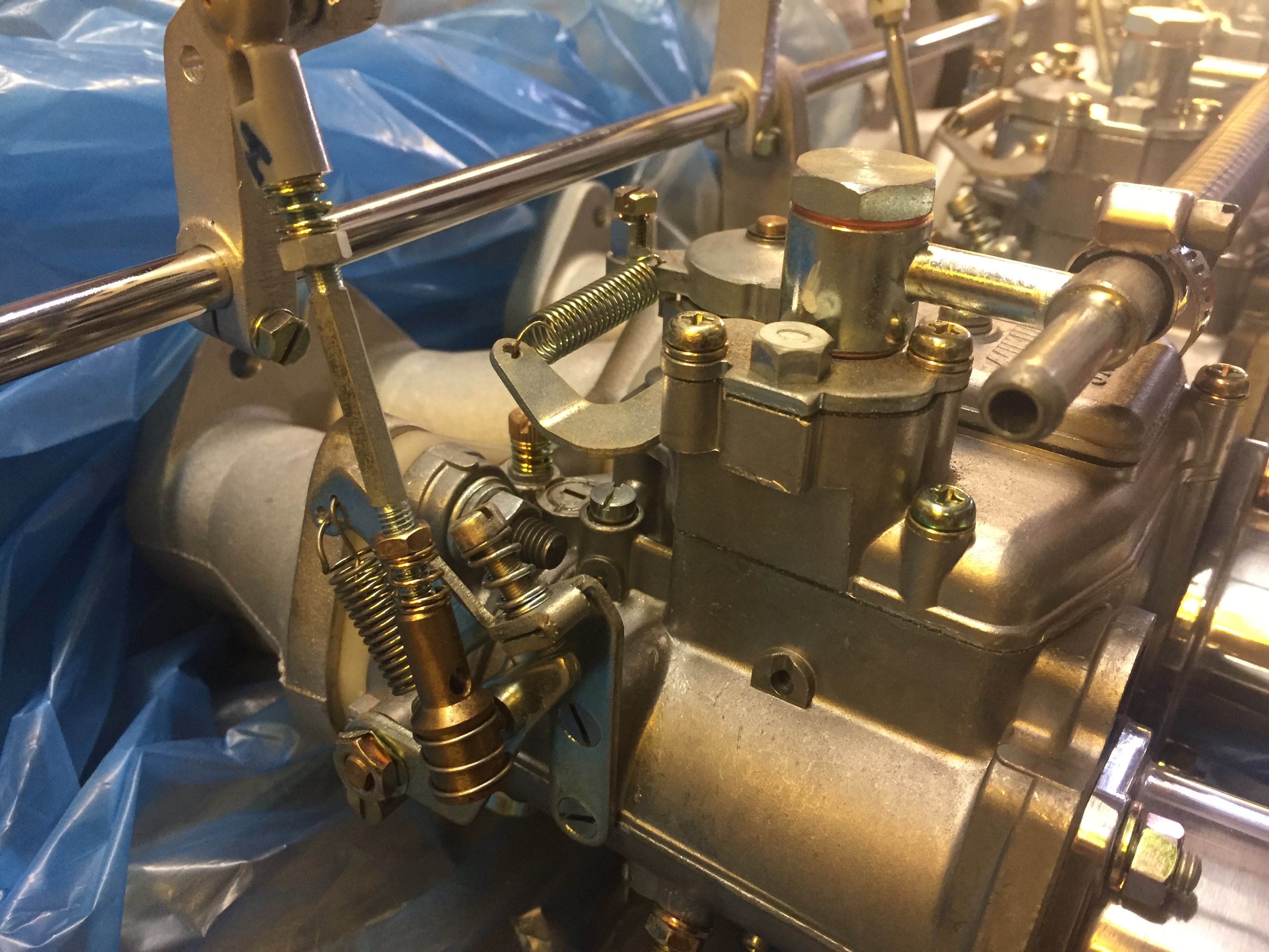
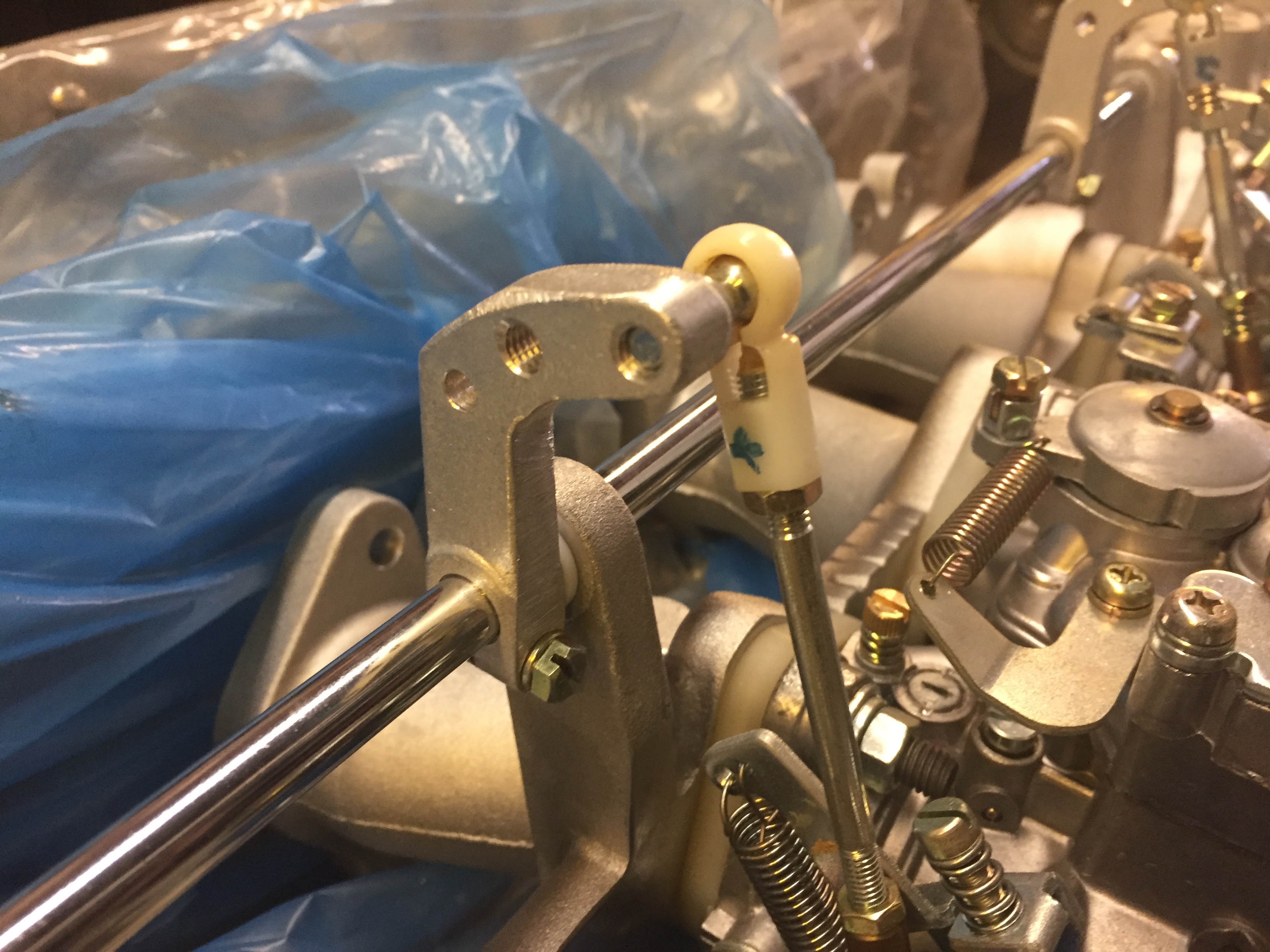
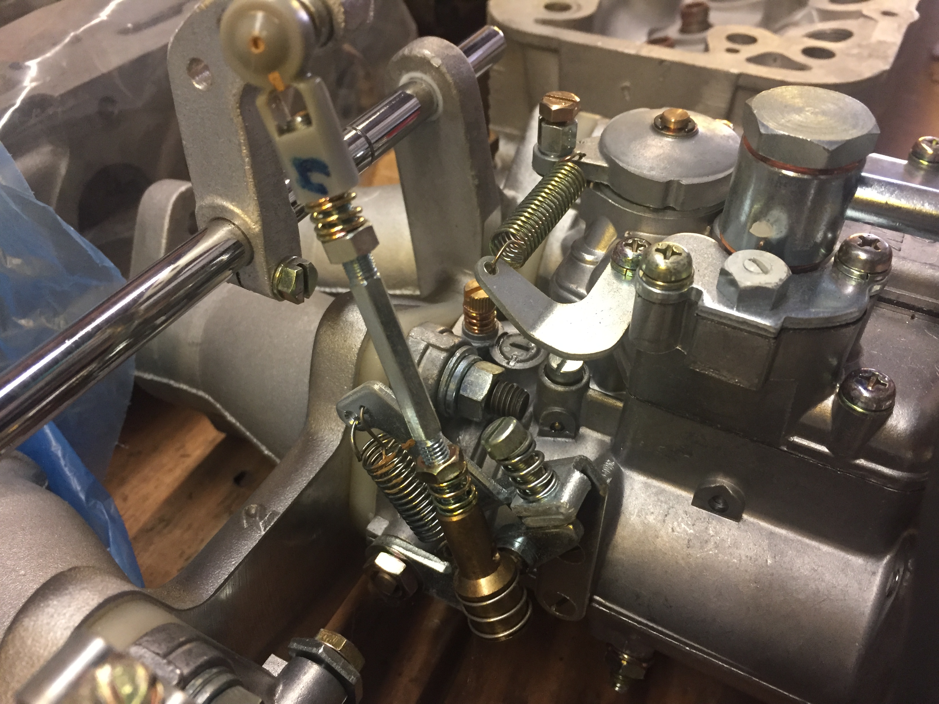
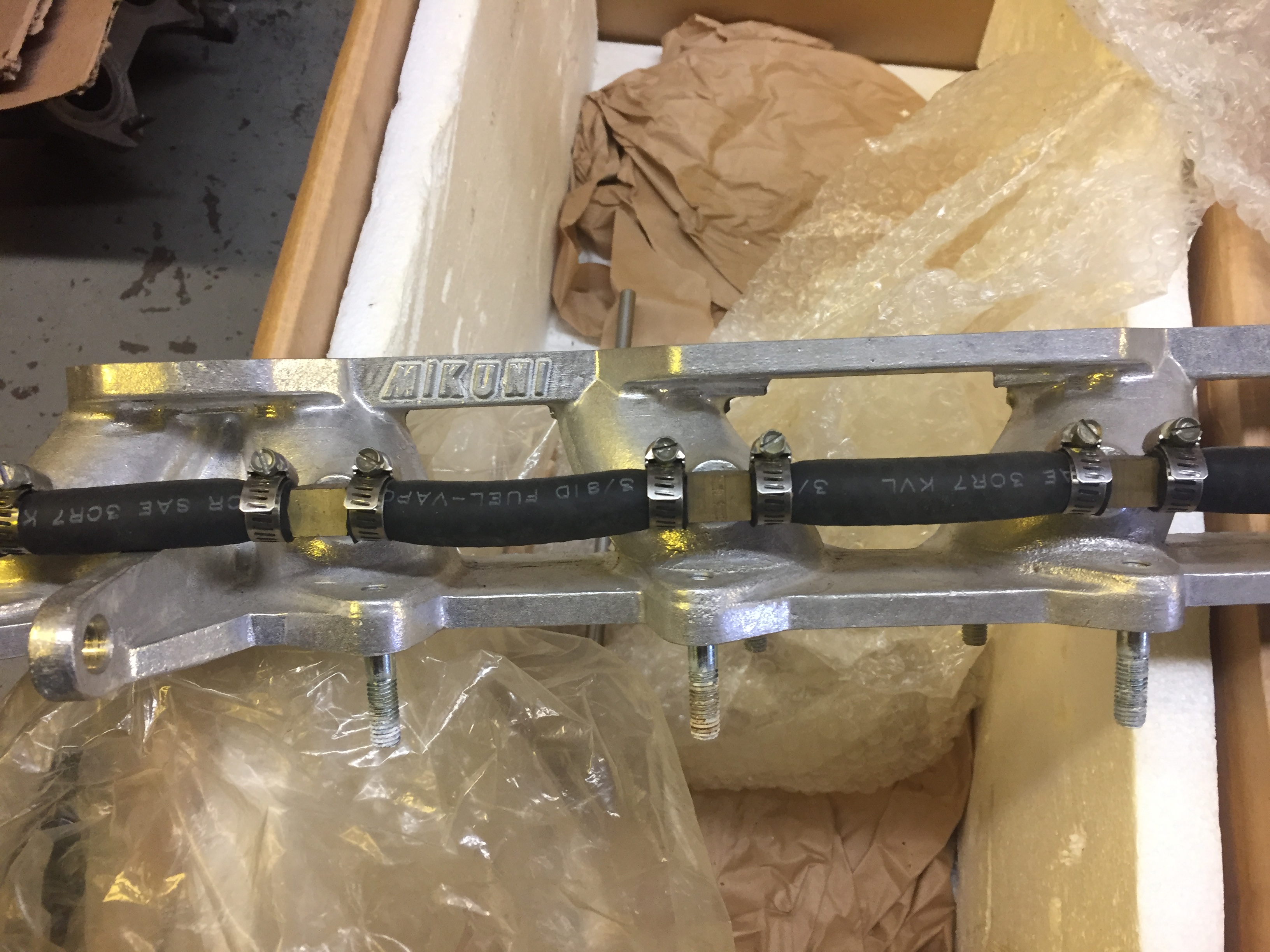
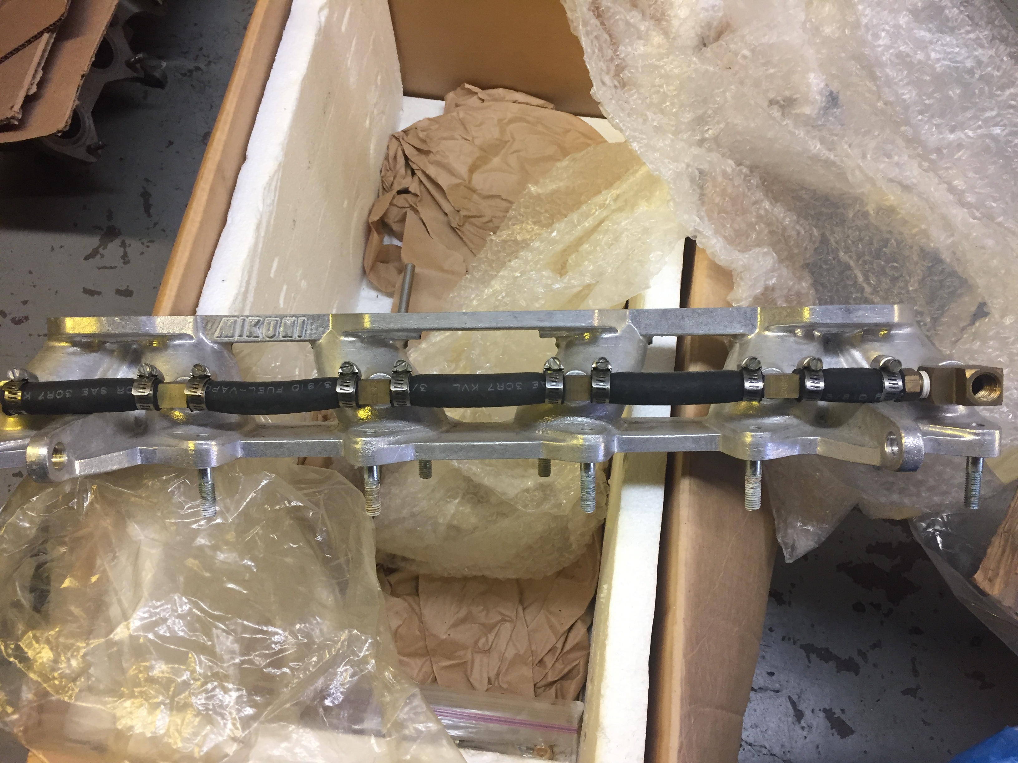
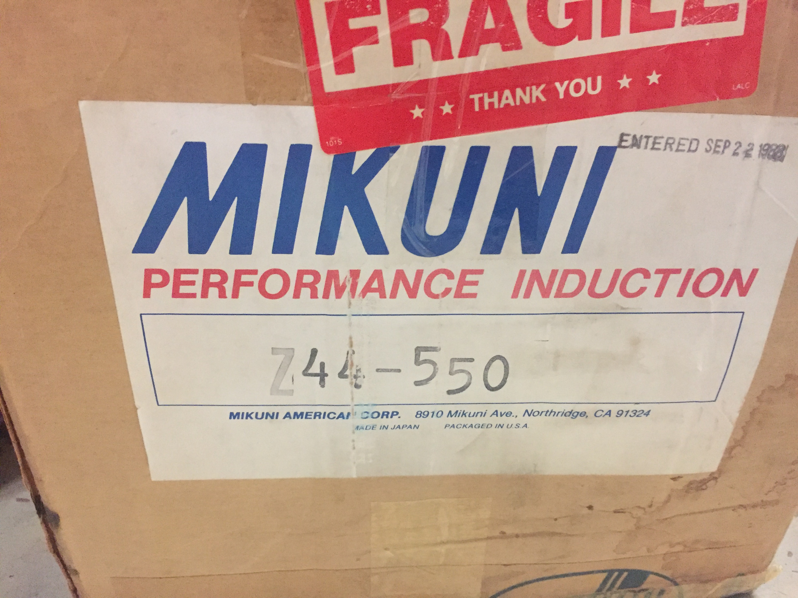
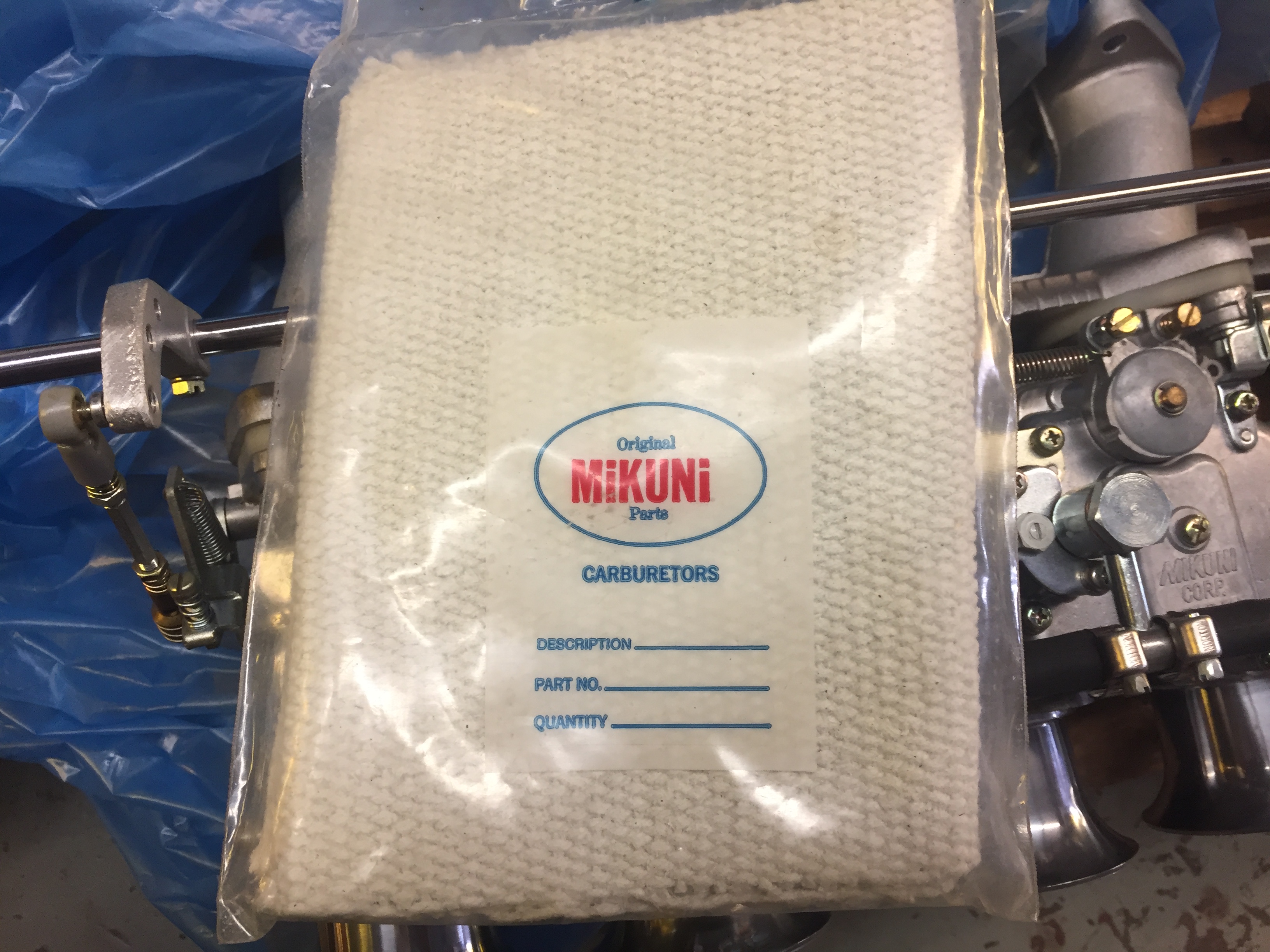
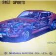
Today i got a long-awaited delivery from Japan. it constisted of three parts: 1) An OEM Adjustable factory competition suspension by KYB. I still need to investigate a bit. I'm not even 100% sure if this was intended for this specific version of car, and i know there were many different versions of adjustable suspension around. Especially this part (I assume it's to adjust the push / pull pressure rate?), ius not seen on all of these adjustable suspensions. As you can see it's not in the best, but restorable condition and one spring is missing, so i got it quite cheap. that's the reason i bought it. Mainly to investigate further and figure out the details. Here a quick reference (top: Adjustable / bottom factory Euro spec 240Z): Meanwhile i was even able to buy a second (complete and better condition) set, which is still in japan and will take another few months to arrive here. but yeah, it will definitely give me further insights. I will definitely need to find some time to find out more and will share the details with you. Here is a reference picture from the Competition / Sports option catalogue: 2) The second item i got is an OEM Sports Option / Competition rollbar replica by Mizukami Auto (JP). According to mizukami it is an 1:1 Copy of an OEM rollbar they have in their shop, but with some improvements to simplify installation and fitment. I think the main difference are the mounting plates on the wheel arches. . Which seem somehow pre-assembled (welded) vs the single screwed-together puzzle-pieces you get from an OEM bar, but otherwise seems to be a quite similar design. What is not visible in my photo is a separate lower plate on the wheel-arch mounts, since they are screwed to the mount sin the picture. but they are detachable, just like the original ones. Since an OEM bar is almost impossible (and expensive) to find these days, i thought this would be the next-best option. I have to say the quality is really high and it looks pretty good and the single pieces are quite complex, which justifies the not-so-cheap pricing. Unfortunately i don't have a chassis in-house at the moment to test fit it. So the next best thing was this cheap mock-up. and i probably even did it the wrong way around without the car as a reference... Nevertheless, it looks good. Here's a reference from the JP Competition / Sports option catalogue (see single plates at the bottom left and right). And here's an installation guide from the Race and rallye preparation manual. From what i understand, every OEM Z should have the installation points prepared in the chassis to install this, but again i was not able to verify this without the car on site at the moment. 3) OK and last but not least i also got this drian plug from Mizukami auto. I mean it would be a shame to not add some small gimmicks when placing a big order, right? Despite a few questionsmarks i think the suspension is quite rare and cool and useful and the rollcage definitely better then the Saito full rollcage i had originally purchased many years ago. Also in terms of registration as a historic car and the general MOT in switzerland. More updates on the suspension topic will definitely come soon and i will also try to test-fit the rollbar as soon as possible.1 point
-
1 pointOOPS! that didn't come out right. The 2M ohm resistor provides bias for transistor so it is almost turning on. The higher the resistor value the lower the voltage(bias) and the transistor might not turn on . The first coil detects the magnets on the flywheel as it passes and generates a small electrical pulse in the first winding. This pulse passes through the 10uF cap going to the base of the transistor and turns it on. Current then flows through the 2nd winding through the 680 ohm resistor. This current produces a small magnetic pulse which gives the magnets a "push" when they pass through the coil and keeps the flywheel turning. If you can push the flywheel to start the motion and the flywheel continues to move then the transistor is working . However, it 's just barely working. That being said I'm not sure that the transistor is turning on hard enough to get the ball rolling , so to speak.1 point
-
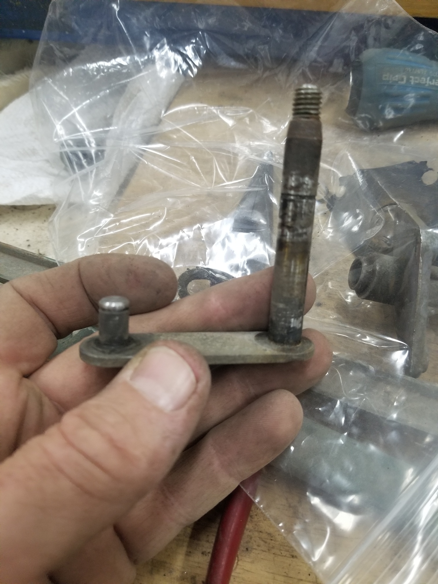
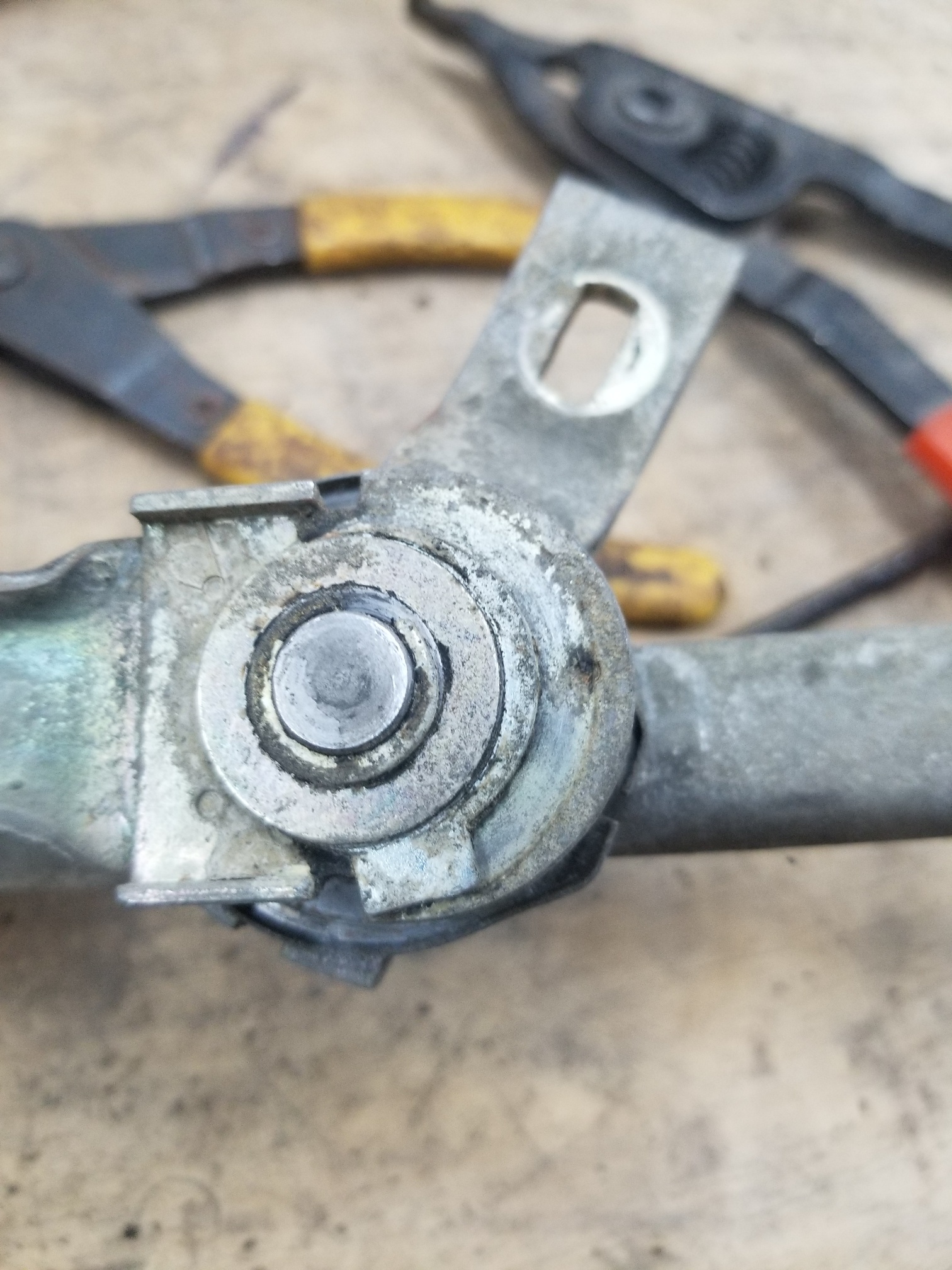
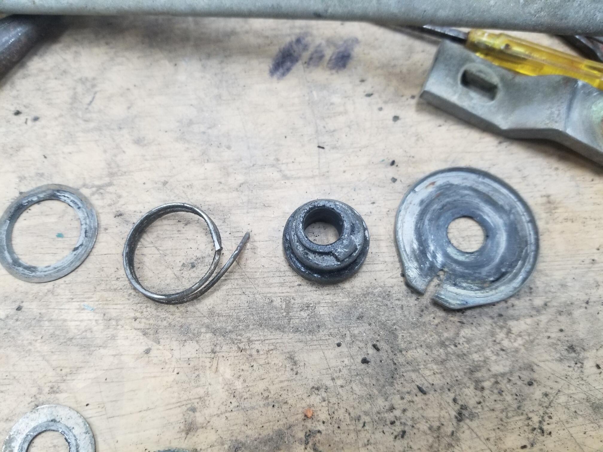
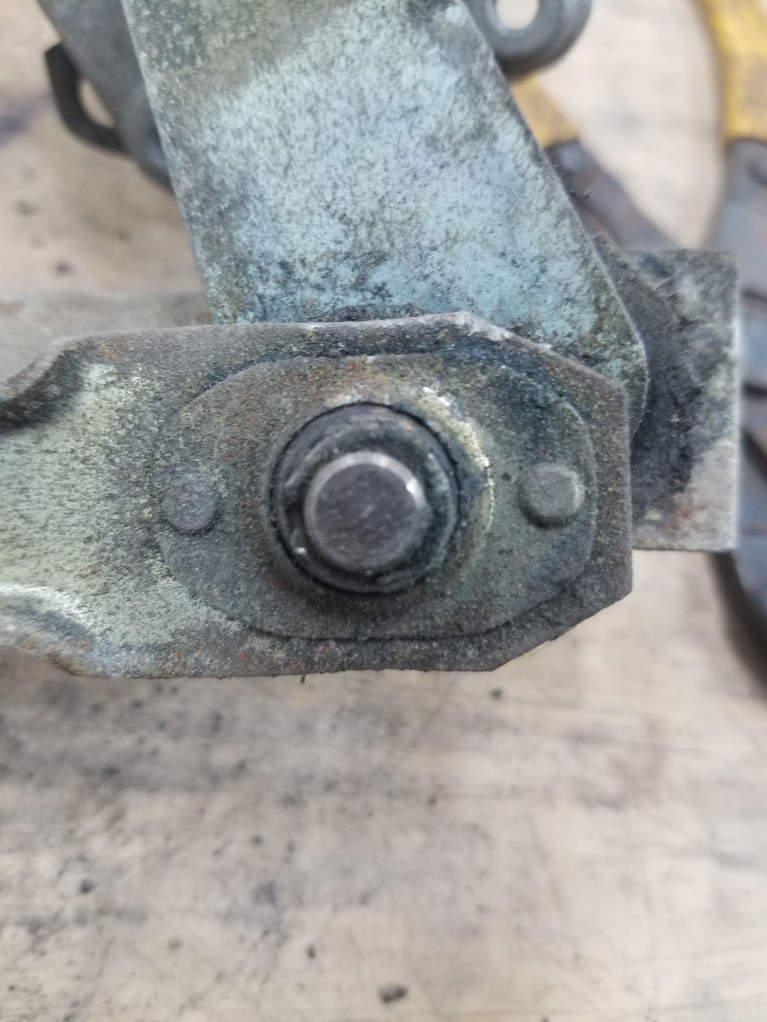
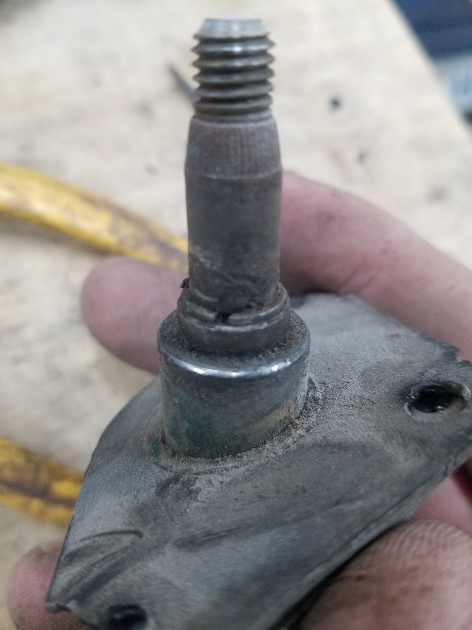
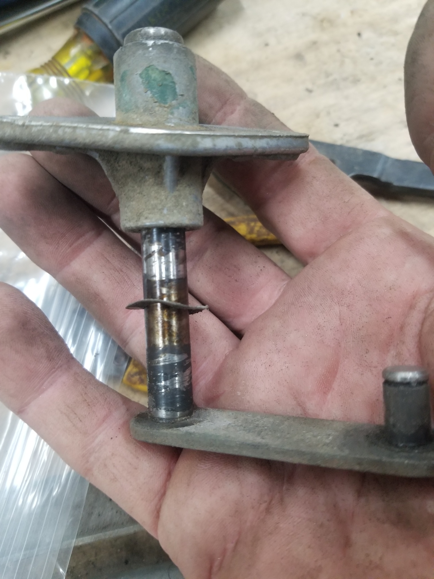
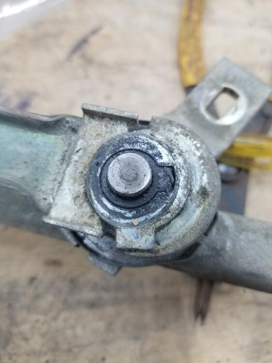
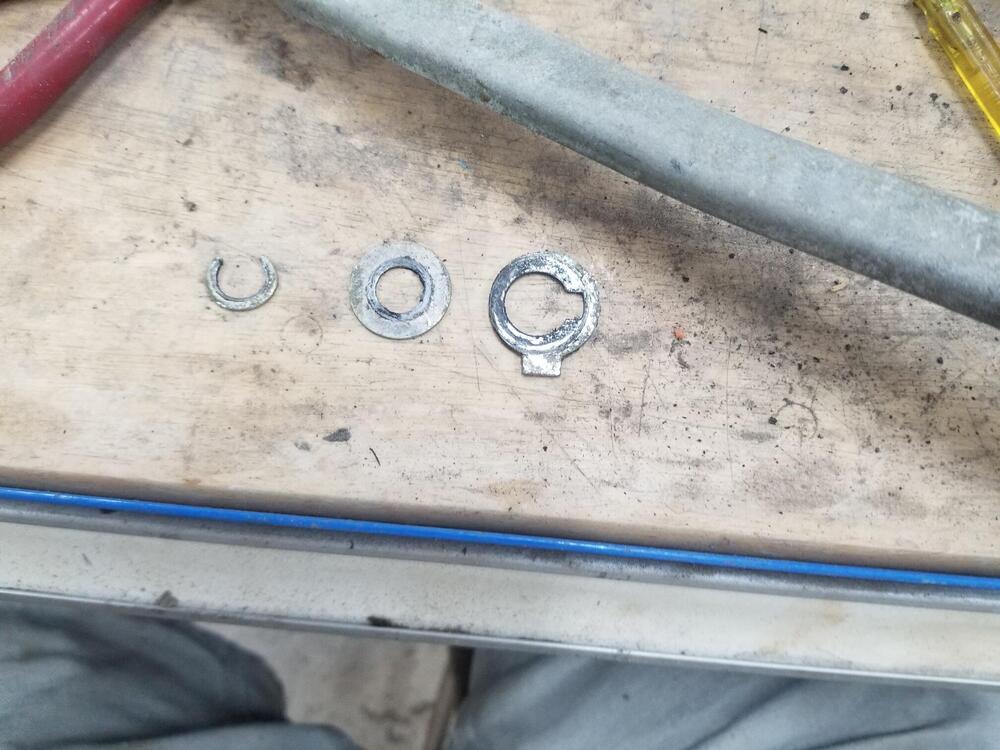
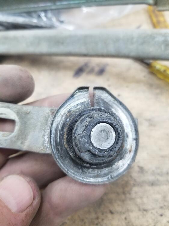
1 pointThis is what the single side spindle looks like This is the drive end of the linkage Order of the top pieces Be careful when disassembling this! There is a spring under here and the first one I did the spring and washer went flying. Order of the lower pieces Another pivot


 1 point
 -
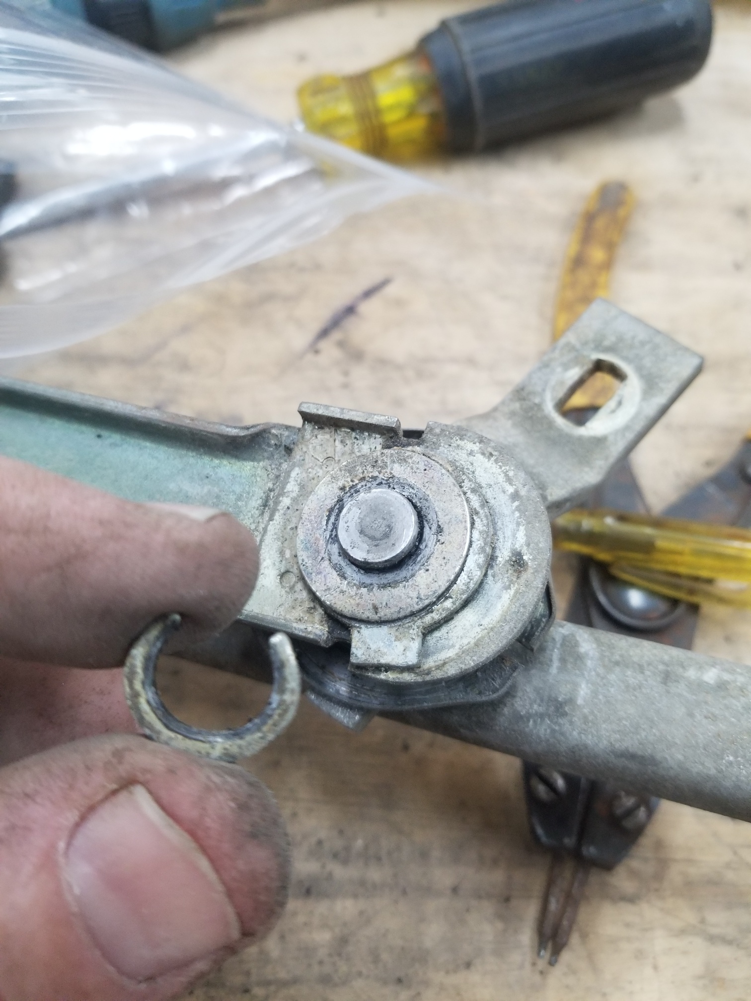
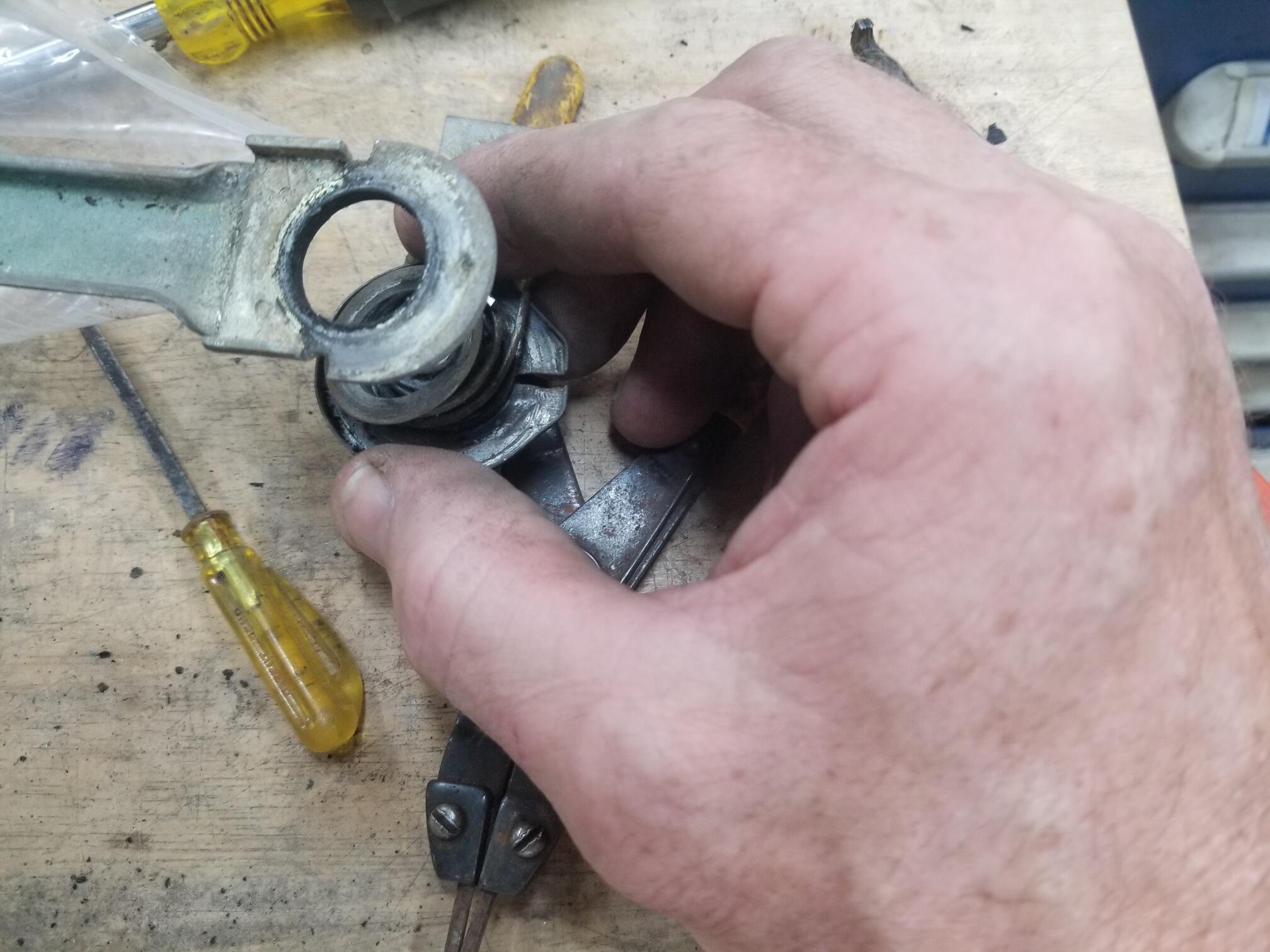
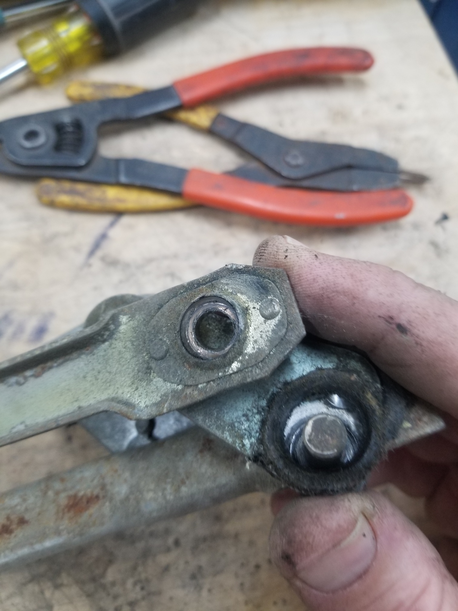
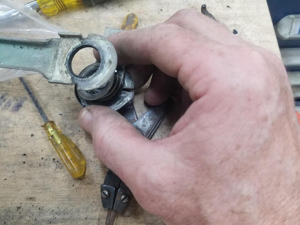
1 pointOn the wiper side of the pivot there is a tiny spring steel ring. Like a little bull ring. I need to find a source for these. Some of them were rusted away When you pull the wiper spindle out of the base there is a wavy washer at the bottom to prevent wear


 1 point
 -
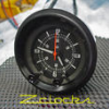
1 pointHave you used your car battery to power your clock. I really don't like using the 9 volt battery as they degrade very quickly. You might power the clock from a car battery and see if thing change. Everything looks good. It acts as if the transistor is not working correctly. When power is applied the transistor is turned on quickly activating the coil which pushes the wheel and everything starts moving. It might be that a cap that was replaced is not the correct value. It might say 10uF , but in reality it could be wrong. I have a cap meter and measure everything I replace because of the poor quality caps on the market. As the Captain suggested you might check the value of the 2Meg resistor. I did some checking on the coil values you have, 490 and 153 ohms, and that is right in line with several circuit boards I have so I don't think that 's the problem. Ron1 point
-
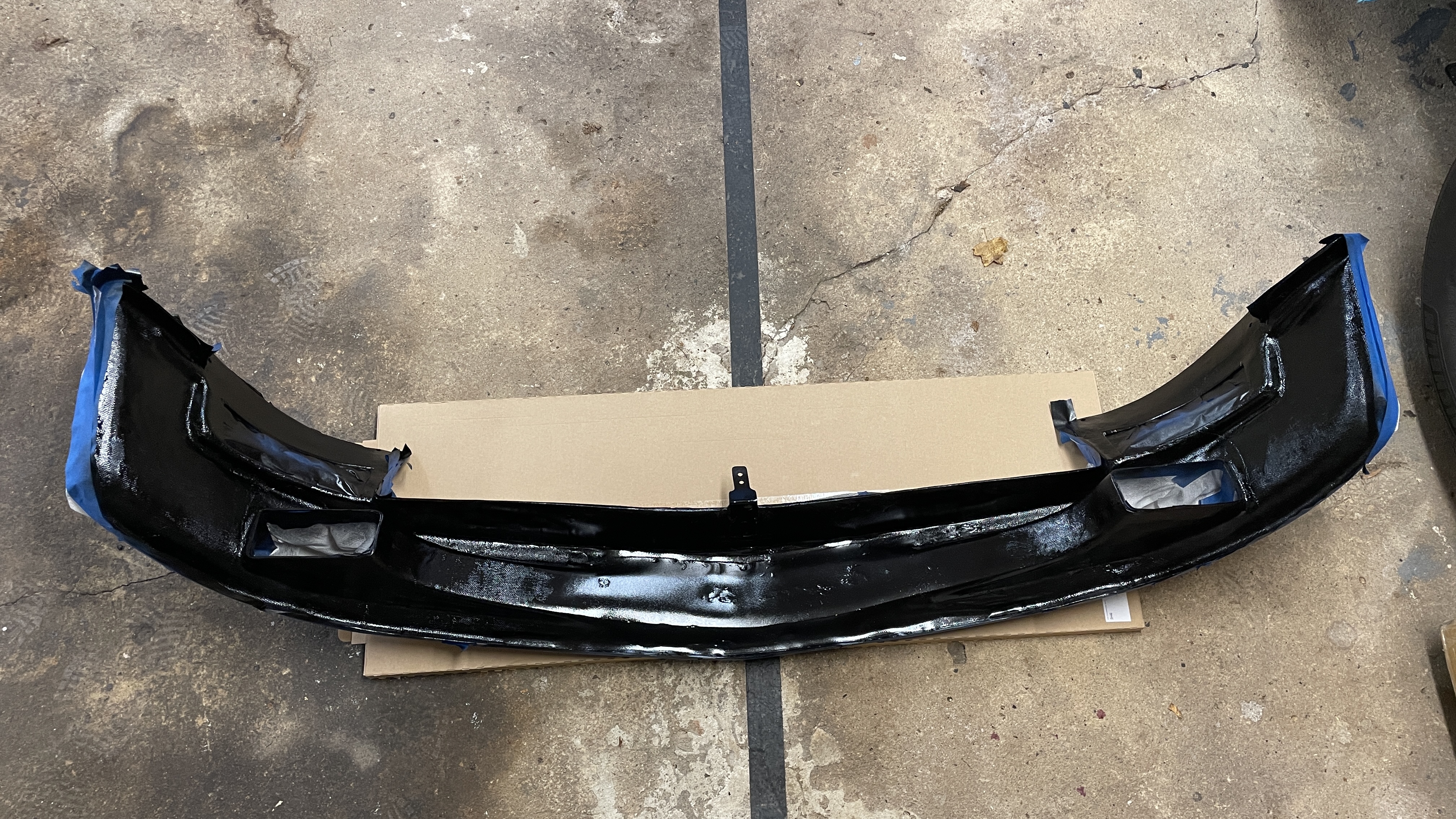
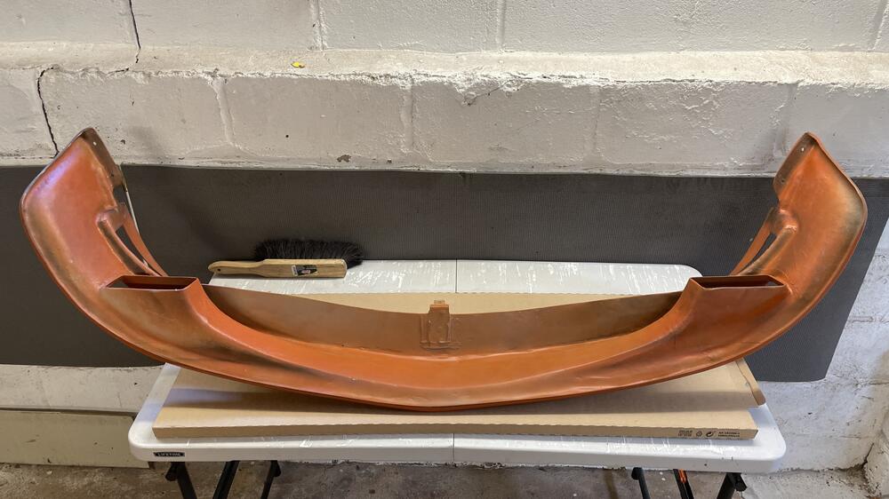
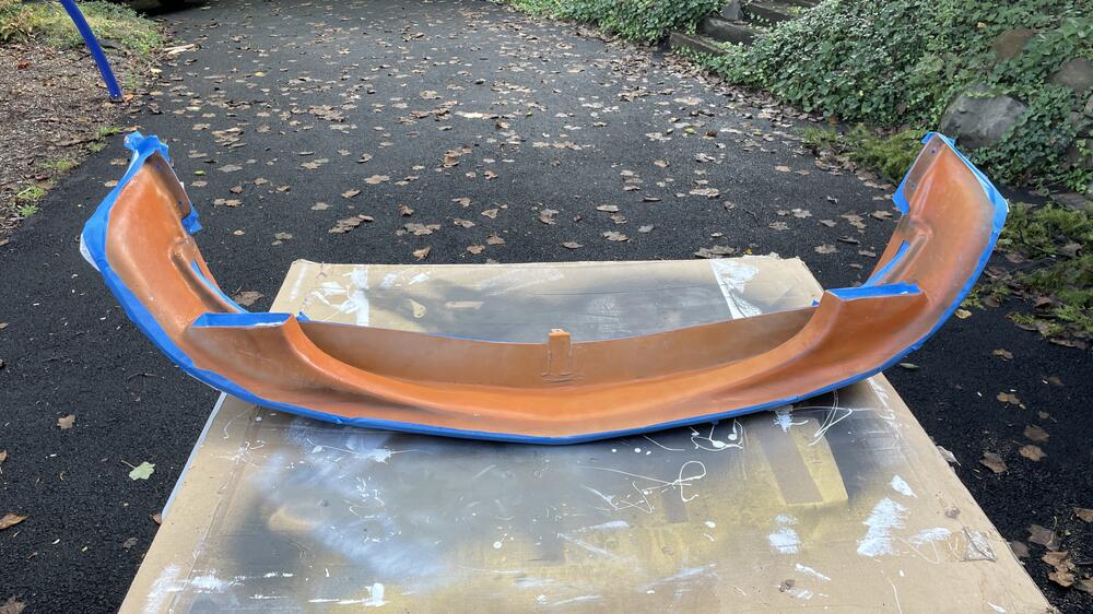
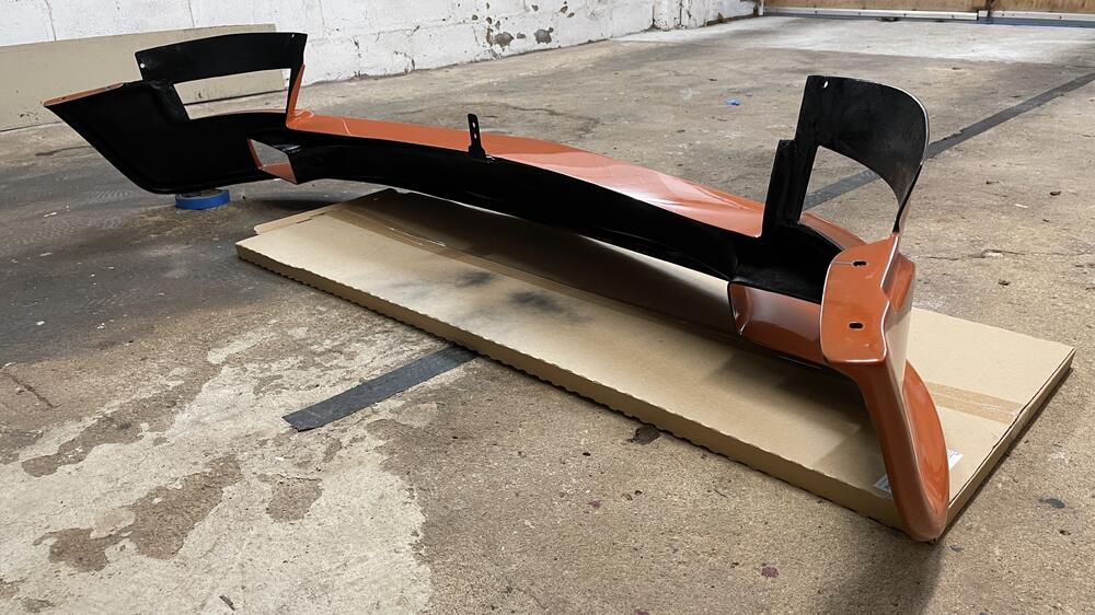
1 pointOne of the many, many things the painter screwed up on my car was not painting the back of the air dam black like I asked him to. Not the most egregious screwup by far, but still annoying when compounded with everything else. I hit this with gloss black and it helps. Doesn’t fix the spots where the primer is showing through the orange but it’s better.
 1 point
 -
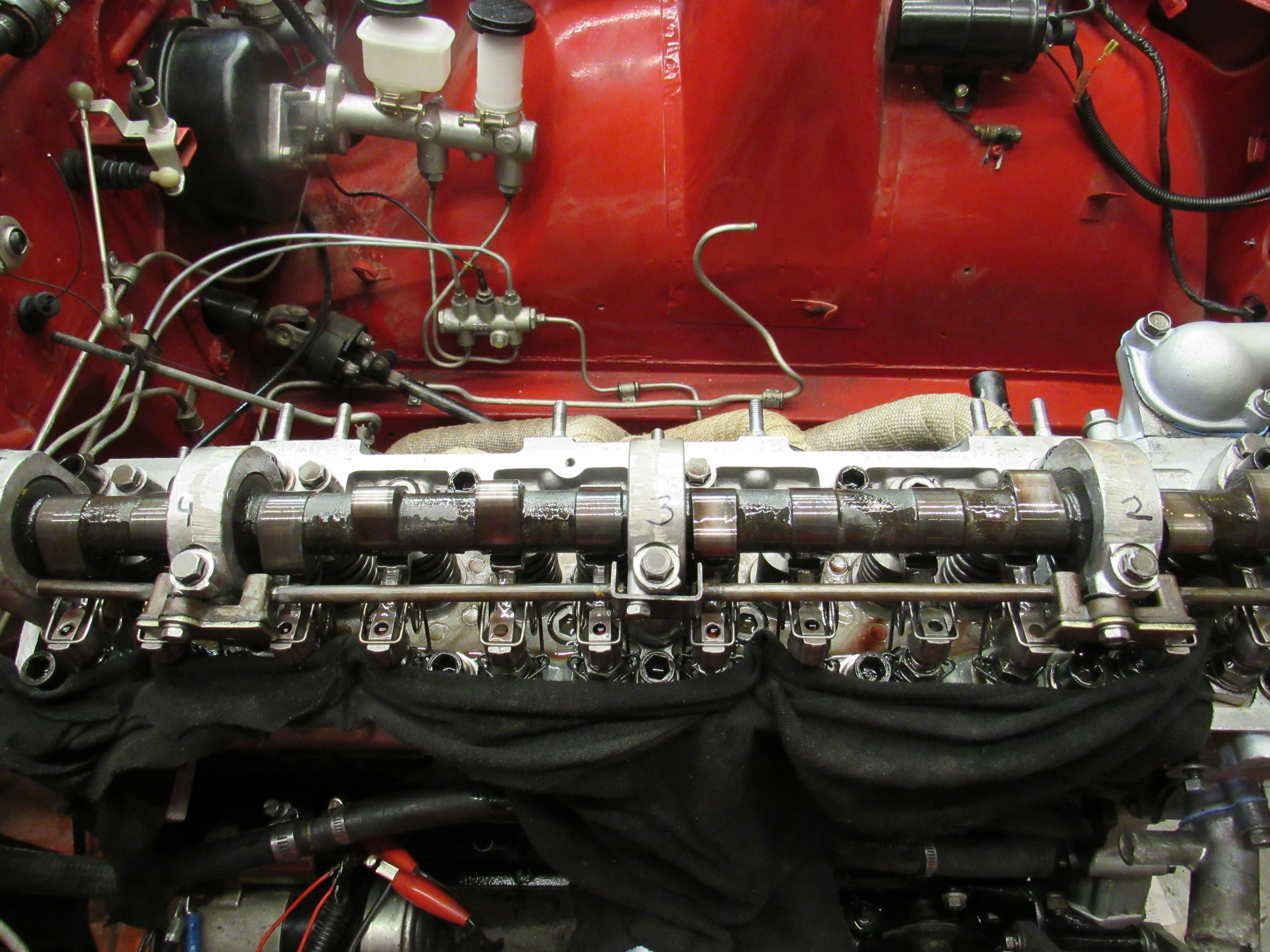
Picked up a set of used cam tower bearings today, came from an E31 head, all within spec, bolted them in and the cam slid in perfectly, first time with no binding! Very pleased. Also, p/u the spray bar from the donor head, it's in much better shape than the other one, there is definitely more oil coming out of the spray bar although certainly no jets of oil, but then the oil is cold and the cam and rockers aren't moving as I spin up the oil pump and they help to splash the oil around.
 1 point
 -
1 point
-
I havd been following this thread and a little suprised no one has commented yet. It is an interesting mod you're attempting and I hope it delivers the results you are looking for. Great detail and plenty of photos so others can follow. Slowly buy surely these parts (AAR for example) are getting harder to find and a possibld update to later more available parts is more than welcome.1 point
-
1 pointMy wife is top notch! She didn't complain at all. I've even had to train my wife not to shop for Datsuns! 🤣1 point
-
1 pointHAHAHA... the best line in this whole topic!! 😂 (For us single guys!) Bart once cleaned car engine parts in his mother's dishwasher hahaha... Hahaha.. I need to know what she said when she came home!! 😅 Next time throw a sausage roll with it's plastic packaging still on in the oven.. then you have an excuse for the smell Hahaha..1 point
-
1 point
-
Seems like he might have paid for the looks and now he's finding out what's underneath as he tries to move it on. Funny that he says he spent years trying to buy it but knows so little about it. Wonder where it will end up next.1 point
-
1 point