


Leaderboard
-

siteunseen
Free Member5Points15,115Posts -

Zed Head
Free Member3Points19,238Posts -

Mike
Administrator2Points23,065Posts -

Av8ferg
Free Member2Points1,538Posts


Popular Content
Showing content with the highest reputation on 08/19/2021 in all areas
-
3 pointsI'll share a story about my Dad, RIP. He never used a torque wrench or impact, just a 24" x 1/2" breaker bar and his brute gorilla arms. My younger sister and my step monster had flats over the years but could not break Pop's strength loose. Had to call roadside assistance everytime. He taught them how to put on the spare but couldn't make them as strong as he was. Me on the other hand was a touch smarter than those girls and used the scissor jack and the opposite weight of the car to break them loose. Needless to say I was his #1 son. To add context, my Dad worked for 40 years at the local Goodyear plant. He rotated all of our tires once a month just for the fun of it.3 points
-
2 pointsCar are way too complicated today. Manufactured obsolescence is a business model. All the plastic and electronics are meant to be thrown away not repaired. If the 12” screen fails in 10 years good luck replacing it or pay a fortune. We have this problem in military aviation. We are forced to upgrade perfectly good items across the fleet because nobody makes the parts anymore. In order to incentivize manufacturing we would pay crazy amounts for otherwise very inexpensive parts. Car companies don’t want your to keep you car more than 10 yrs. I once owned a BMW. The pasts were so outrageous I got rid of it. $1800 for one headlight assembly because it would follow the road. The car had more plastic than a Las Vegas stripper. Plastic coolant parts? There is beauty in simplicity. You can almost keep your classic Z running forever with little cost because it simple proven technology. The second part of the auto problem is government regulations which continue adding complexity and cost to cars. The new infrastructure bill just passed by the Senate requires all US cars to have Drunk Driver Detection systems installed at manufacturing. This drives car prices out of reach of the lower income population segments and makes repair and maintenance outrageous. There are always unintended consequences of regulation. I’m curious to see what Nissan gives us but their recent history isn’t giving me much confidence. As far as EVs, they’re coming like it or not. Won’t be long before you are guilted to sell your gas powered vehicle or the government forces your hand like CA has done. Sent from my iPhone using Tapatalk2 points
-
1 pointI just finished up the last of the tar mat templates and uploaded them to our cad files section in downloads.
 1 point
 -
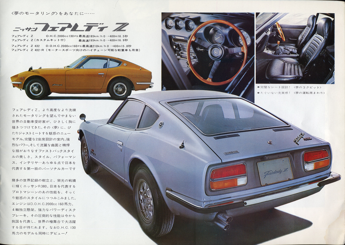
1 pointNot the case. S30-S and S30-D, Fairlady Z and Fairlady Z-L started the ball rolling for the S30-series and the tradition was carried through subsequent generations. The '240Z' name was an afterthought. How about 1969:
 1 point
 -
1 pointI learned to have them checked right out of the box, before I leave the store. Burn me once, shame on you. Burn me twice, shame on me.1 point
-
1 pointI was referring to the horn button. Looks similar to the '75 and '76 280's to me? Those LED gauges freak me out when they peg out then come back down when you first turn the key on.1 point
-
1 pointJust a note, be careful if you stick something into the top of the cowl trying clean debris from within rubber drain tube. Ive had one of those tube tear on me, last time I checked they were expensive. >.>1 point
-
Not exactly. I've talked with him about this and he does not do anything that directly fits the MSA headers out of the box, it will require a small bit of pipe and fabrication to mate the two systems. It did not sound like very much, and knows of others who have mated the two systems so it can certainly be done.1 point
-
1 point
-
1 pointGood explanation of testing Steve. My usual method is the second you illustrated. With the two B/W and the G/W wires disconnected, I turn the ignition switch to the ON position then check the two B/W wires for battery voltage. In stock config the B/W wire with voltage would attach to one side of the ballast, the G/W to the other side of the ballast, and the remaining B/W to the "+" side of the coil. An aside to understand the circuit: The early tachometer is "current sensing" - it calculates RPM by how much current is flowing through the coil to provide spark at the plugs. (If there were no ballast resistor there would be no need for the double wire and return the tach/coil system uses.) Power for the coil comes from the ignition switch in both the ON and START positions. Nissan (and everyone else in that era) used a ballast resistor to increase longevity of the distributor points - SO, they want the current flow to the coil to run through the resistor. Wait, we also need a tach signal so we have to take that wiring to a loop it at the back of the tach - then bring it back to the coil. So, They use the B/W (battery voltage at IGN ON) to run to the ballast resistor, the G/W brings it back under the dash to the tachometer, and the second B/W comes out of the tach loop and all the way back to the coil "+" to make sparks happen. IGN SW B/W -> ballast -> G/W -> tachometer connector -> B/W -> coil "+"1 point
-
1 pointHi all, Now that the Z prototype has moved to production status, I've gone through our forums database and created a new forum for discussions around the New Z. Feel free to use the forum to link news, sightings, opinions, and experiences around the latest Z-car. Enjoy! Mike1 point
-
1 pointIf only you were on this side of the pond, I have a few that don't get nearly enough use. Thanks again!1 point
-
@AK260 brilliant! As long as it is not going to impact that delicious delicious torque curve, that is what I am interested in. Thanks much for the explanation on scavenging. Watched a few videos on YouTube which had me spinning!1 point
-
Keep your exhaust pipe the same dia. as the collector.1 point
-
It will be interesting to see the trajectory of 240Z prices once the 400Z is out there for wide public consumption.1 point
-
The prices are trending up. That 300K one really screws up the resolution. I filtered it out. https://bringatrailer.com/datsun/240z/?q=240z
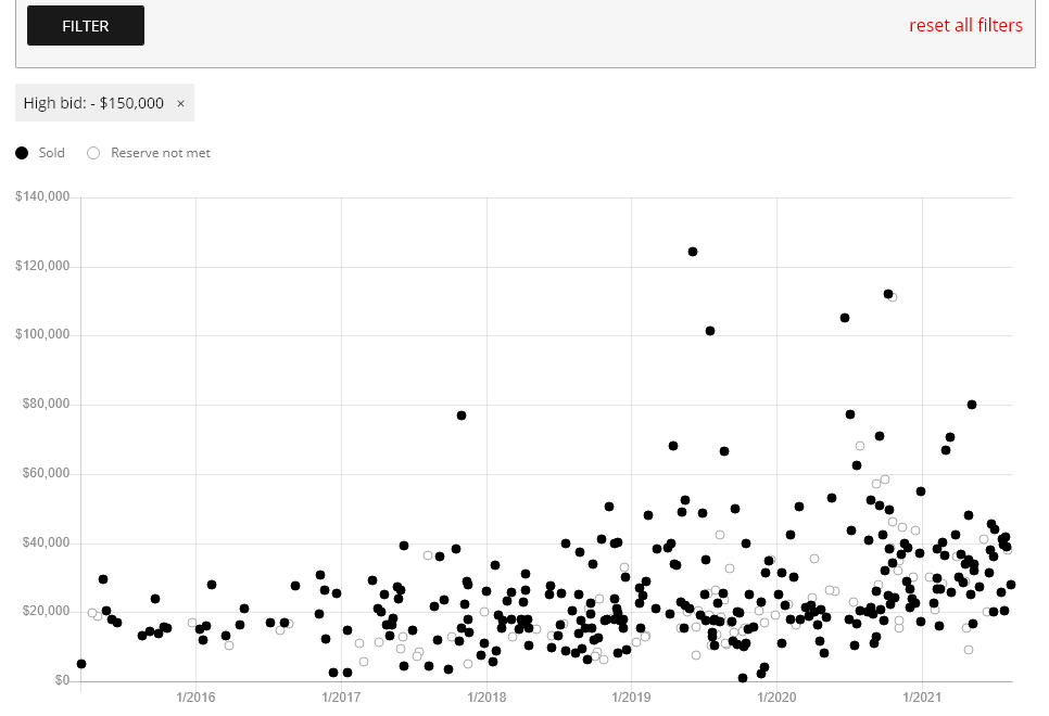 1 point
 -
1 point
-
1 pointhttps://www.gorilla-auto.com/replacement-keys "A Wheel Lock Registrations Key is required to identify the unique key for all Original Gorilla Wheel Locks, X2 Locks, Gorilla Guard or Small Diameter Wheel Locks. Replacement Small Diameter Lug Nut and Hex Lug Nut Sockets can also be ordered using Key Registration Number or Part Number stamped on your Gorilla socket. Why do I need my Wheel Lock Key Registration Number? We are the leading wheel lock manufacturer for good reason, your unique wheel locks and key are nearly impossible to identify through simple visual inspection. Your unique key/lock combination is one of thousands of possible combinations which means your investment is protected."1 point
-
1 pointIt's done by computer, and it's not a mold, it's a milling machine. What good is a lock if one key fits many of them? That would be insane.1 point
-
1 point
-
1 point
-
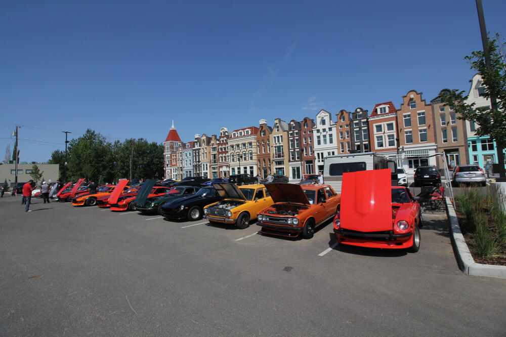
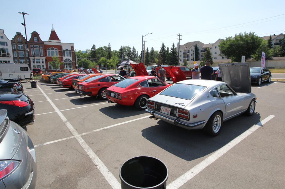
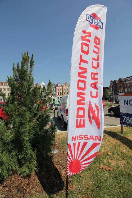
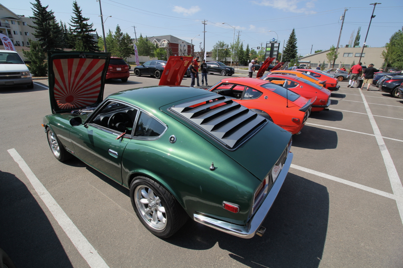
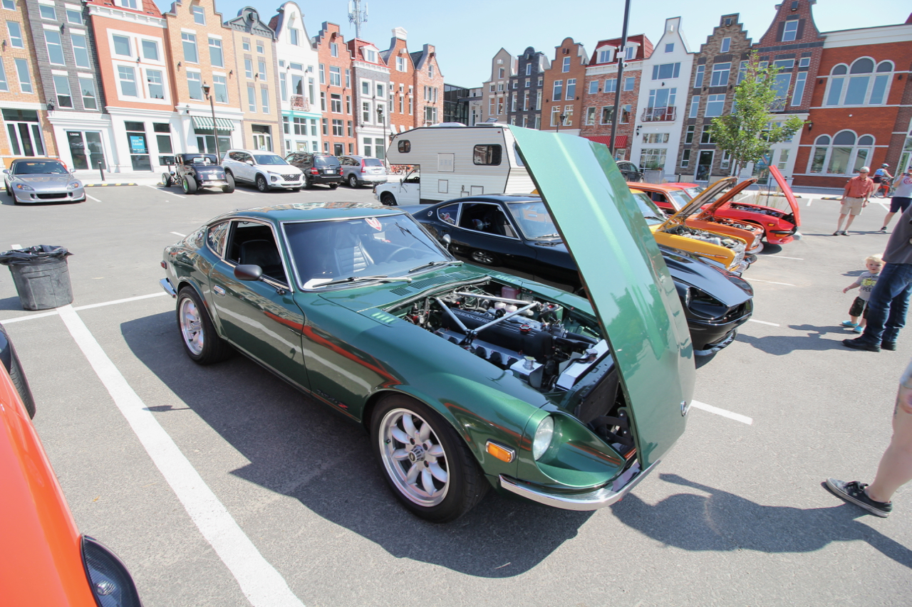
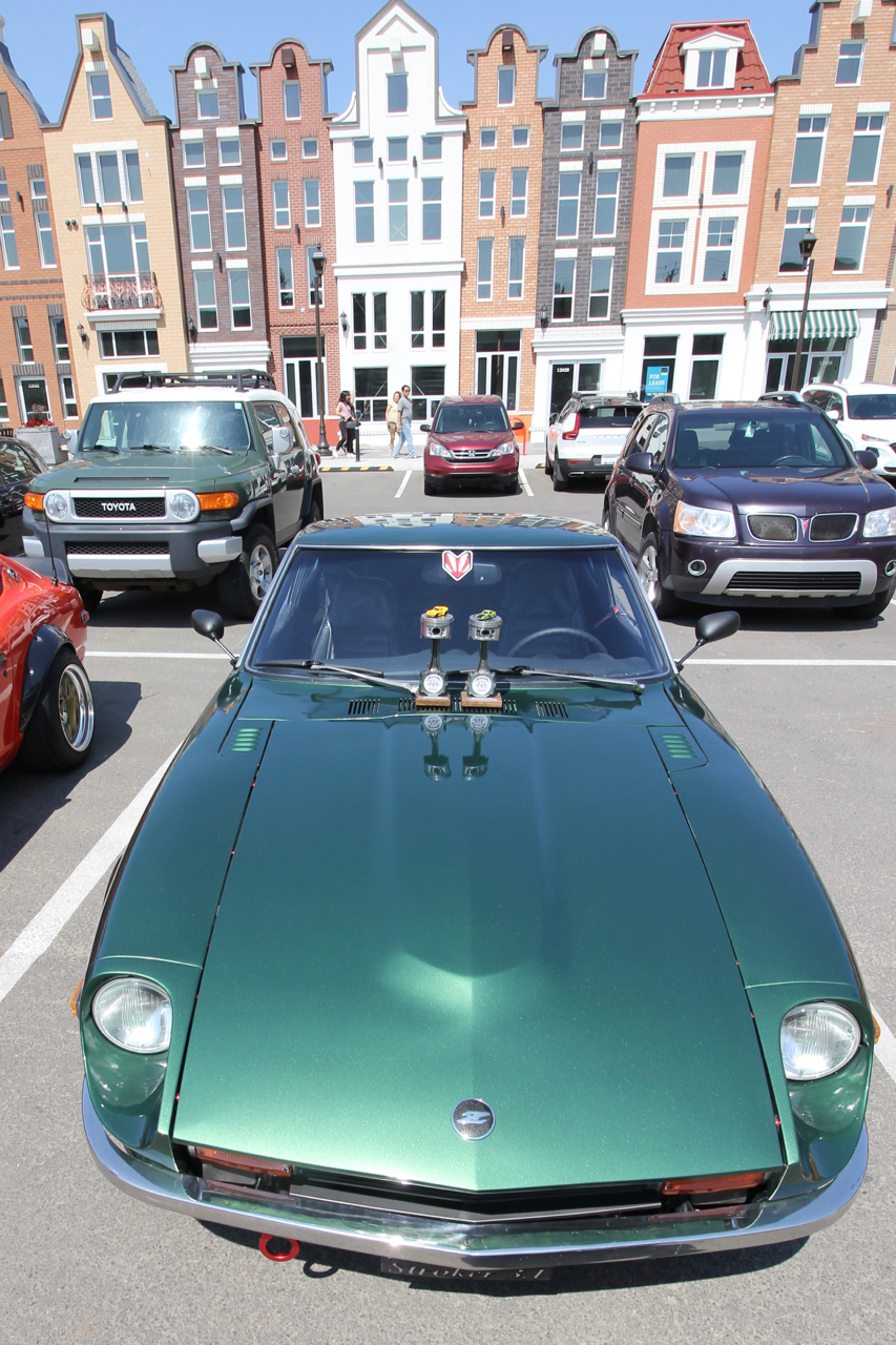
1 point1 point1 pointWell, it has been a long time coming, but I finally got the car out to a car show. Went to the 30th Anniversary of the Edmonton Z Car Club Car show on Saturday. Wow! Where did all of these S30's come from! It was a great turnout with lots of great cars. I am over the moon thrilled with SASSZ and how she looks in the sunlight. We weren't the only ones apparently because we took first place for the S30 class and Best in Show to boot! Validation after all this time feels amazing... Thanks to everyone on this forum that have helped push me along with advice and encouragement, parts and knowledge. This was indeed a village effort to get me this far!


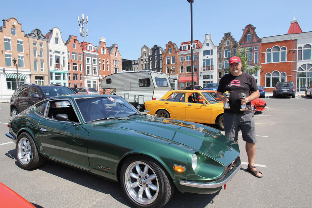 1 point


Important Information
By using this site, you agree to our Privacy Policy and Guidelines. We have placed cookies on your device to help make this website better. You can adjust your cookie settings, otherwise we'll assume you're okay to continue.