


Leaderboard
-
ConVerTT
Free Member6Points422Posts -
dmorales-bello
Free Member6Points627Posts -

wheee!
Free Member4Points4,607Posts -
grannyknot
Free Member4Points5,158Posts


Popular Content
Showing content with the highest reputation on 02/13/2020 in all areas
-
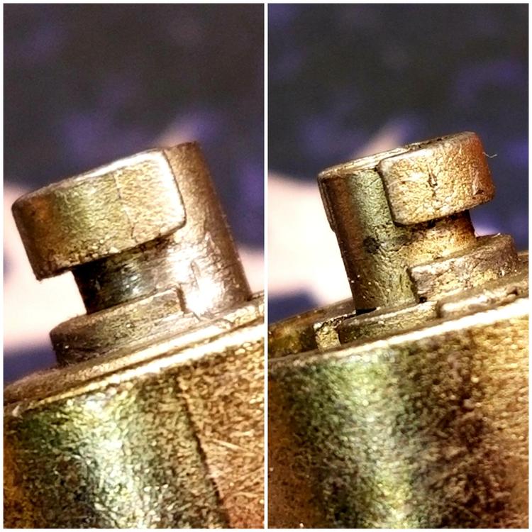
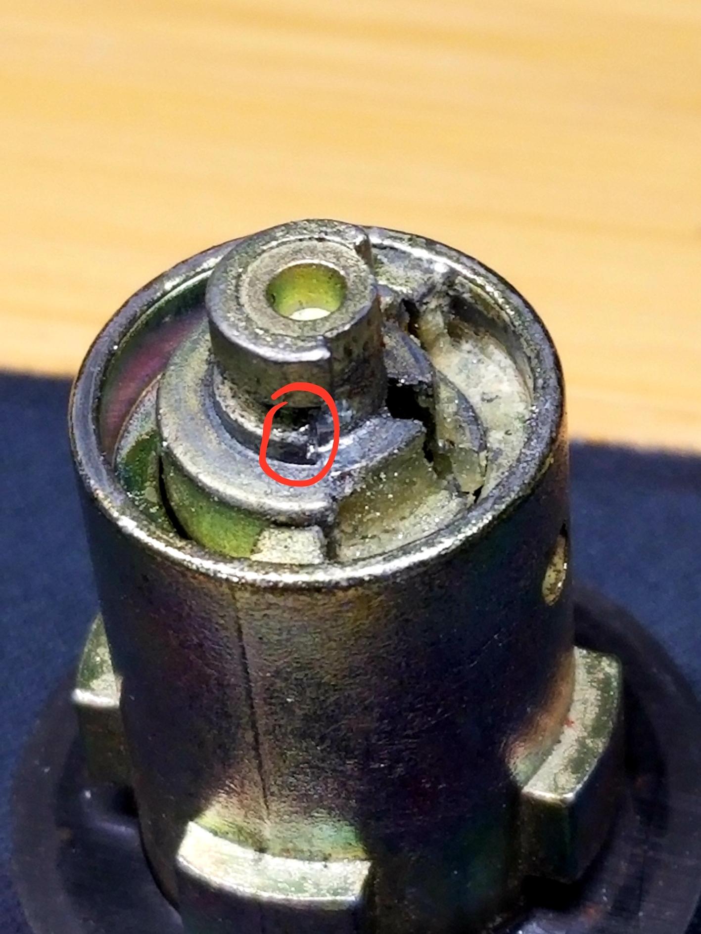
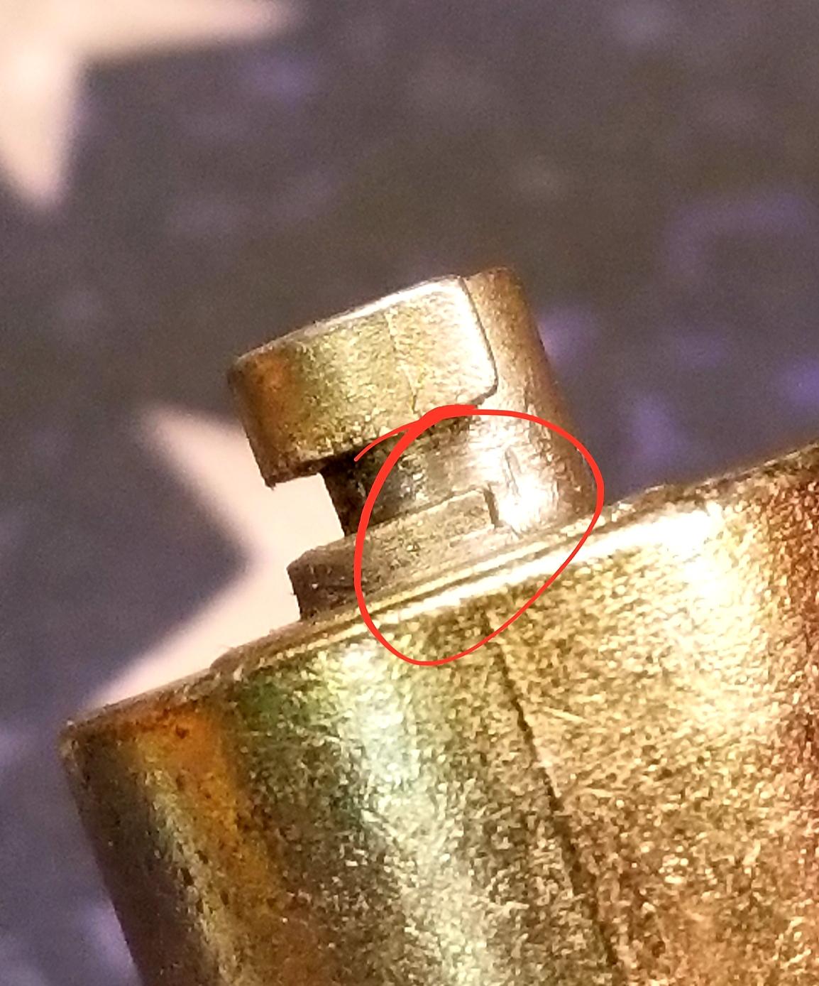
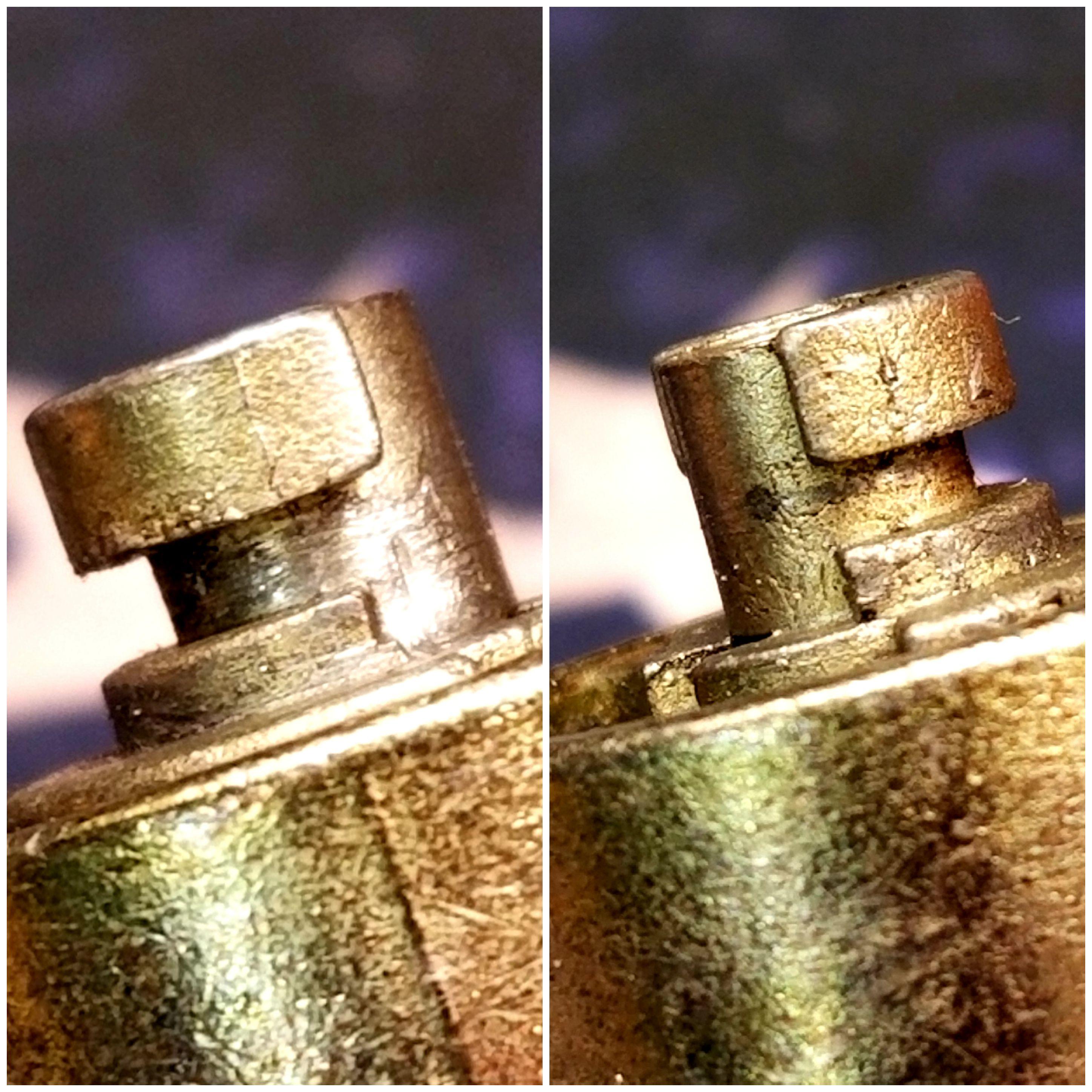
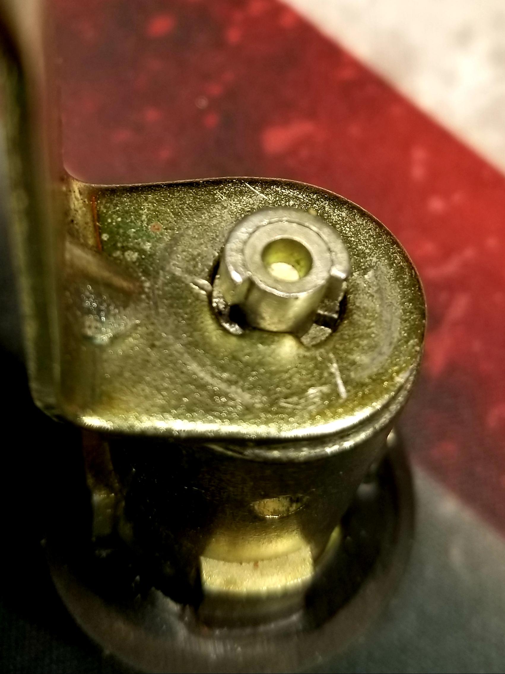
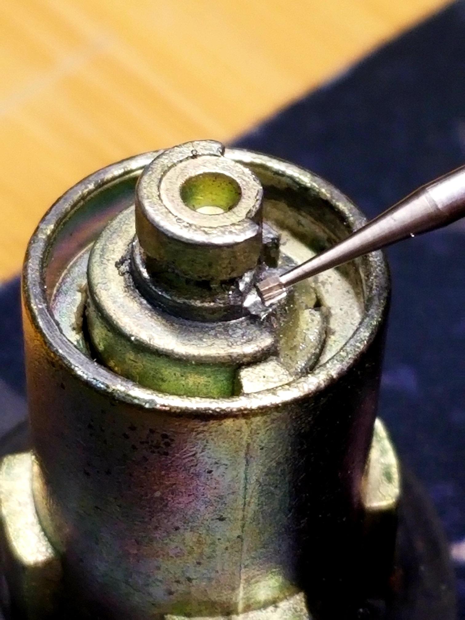
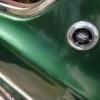
3 pointsRan into the same problem described earlier in this post (that refuses to die!!!). My driver side door would lock with the key yet would not unlock. Not totally convinced that the hanger wire repair will be long lasting and wanting a method that (if failed) would still allow me to repair the cylinder via the FUA technique described before, I decided to try a different approach without the addition of any "parts". The wear on the flat "shoulder" of the cylinder where the arm makes contact and pushes it to rotate, transforms that shoulder into a type of ramp which allows the arm to slide over that edge thus preventing rotation of the arm. When I examined the worn ramp effect under magnification I noticed that the wear on the cylinder metal was truly minimal but the fact that the 90 degree (flat) shoulder was minimally altered rendered the rotation of the arm ineffective. With the use of a fine diamond burr on the Dremel I shaved a minimal amount of metal at the base of the "ramp" transforming it again into a flat step, very similar in shape to the unworn one on the other side of my cylinder (the side used to lock the door). To my surprise, the remedy proved immediately effective mainly because the original shape of the "shoulder" is attained with very minimal loss of material (less then 1mm) and no extra parts (wire) are needed for the repair. Total cost of repair; $0.00. Now my cylinder locks AND unlocks the driver side door properly. Granted, eventually the cylinder metal will wear again but by that time maybe ZCar Depot will make replacement cylinders for the '77 and '78 Zs that can be keyed alike with the original Nissan keys. Here are some illustrative pics: Pic above showing the deformed "shoulder" on the cylinder (circled in red). Ramp squared off and back to original shape with fine diamond Dremel burr. Unlock side (left) and Lock side (right) are quite similar after Dremel work. Lock arm back in position and working properly to either side.


 3 points
 -
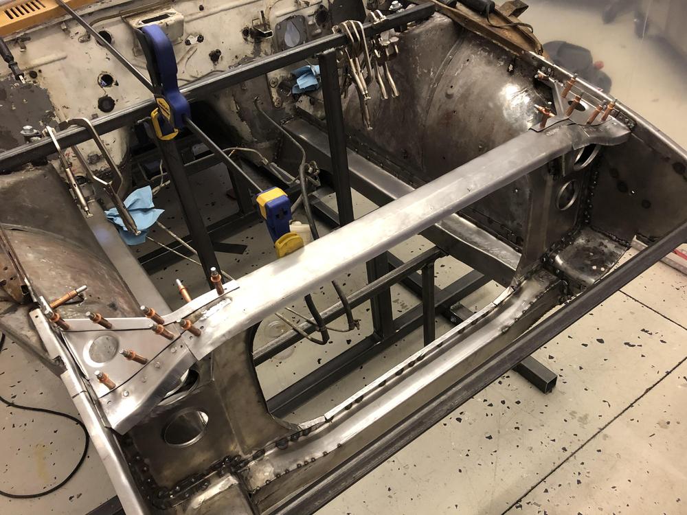
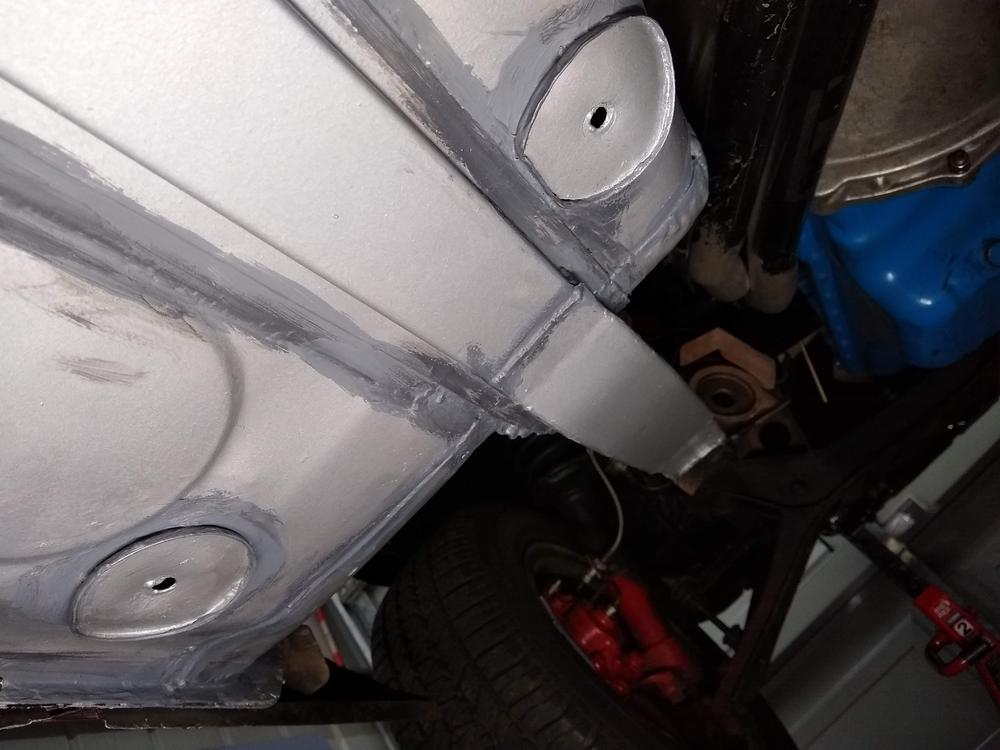
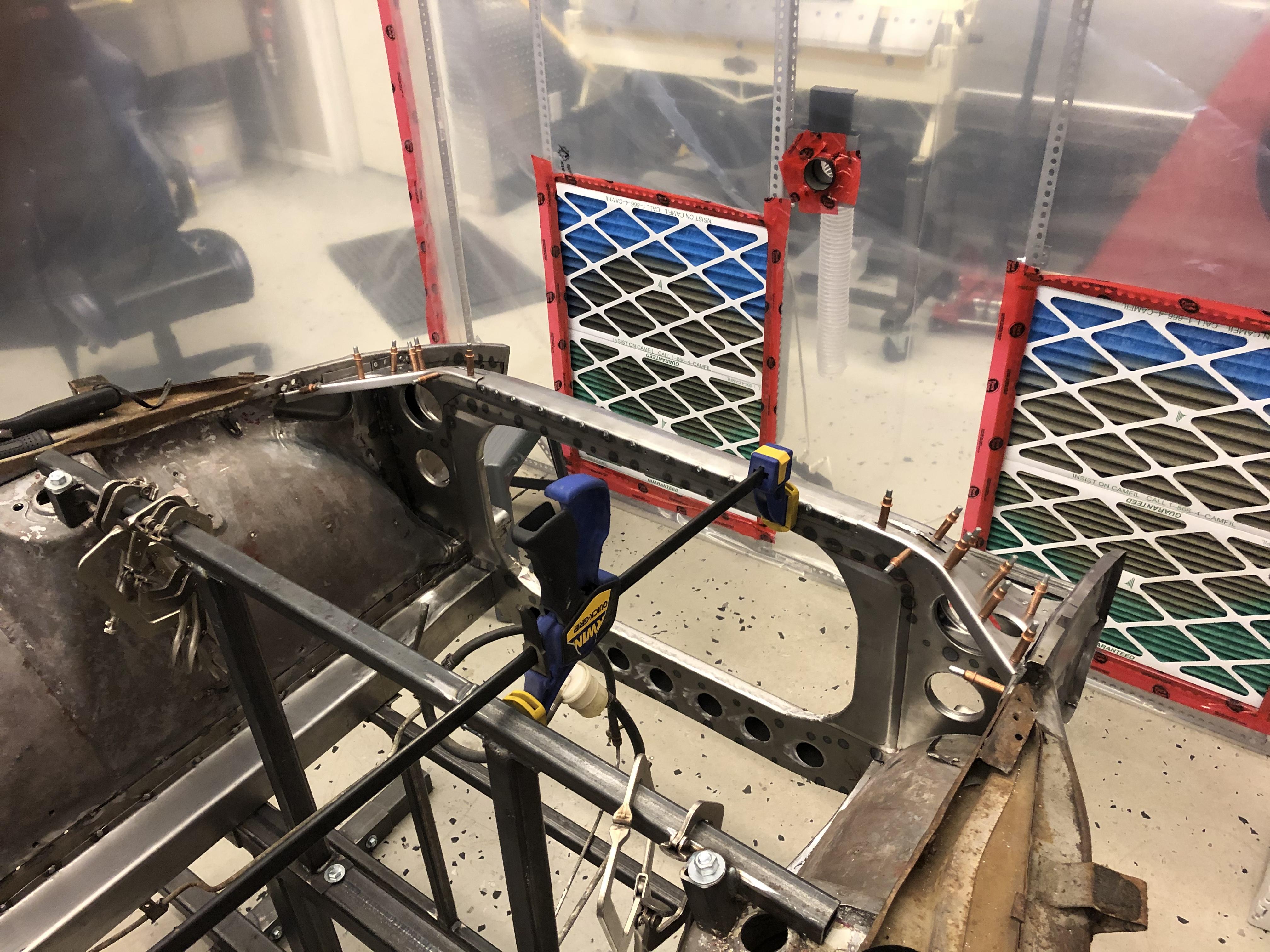
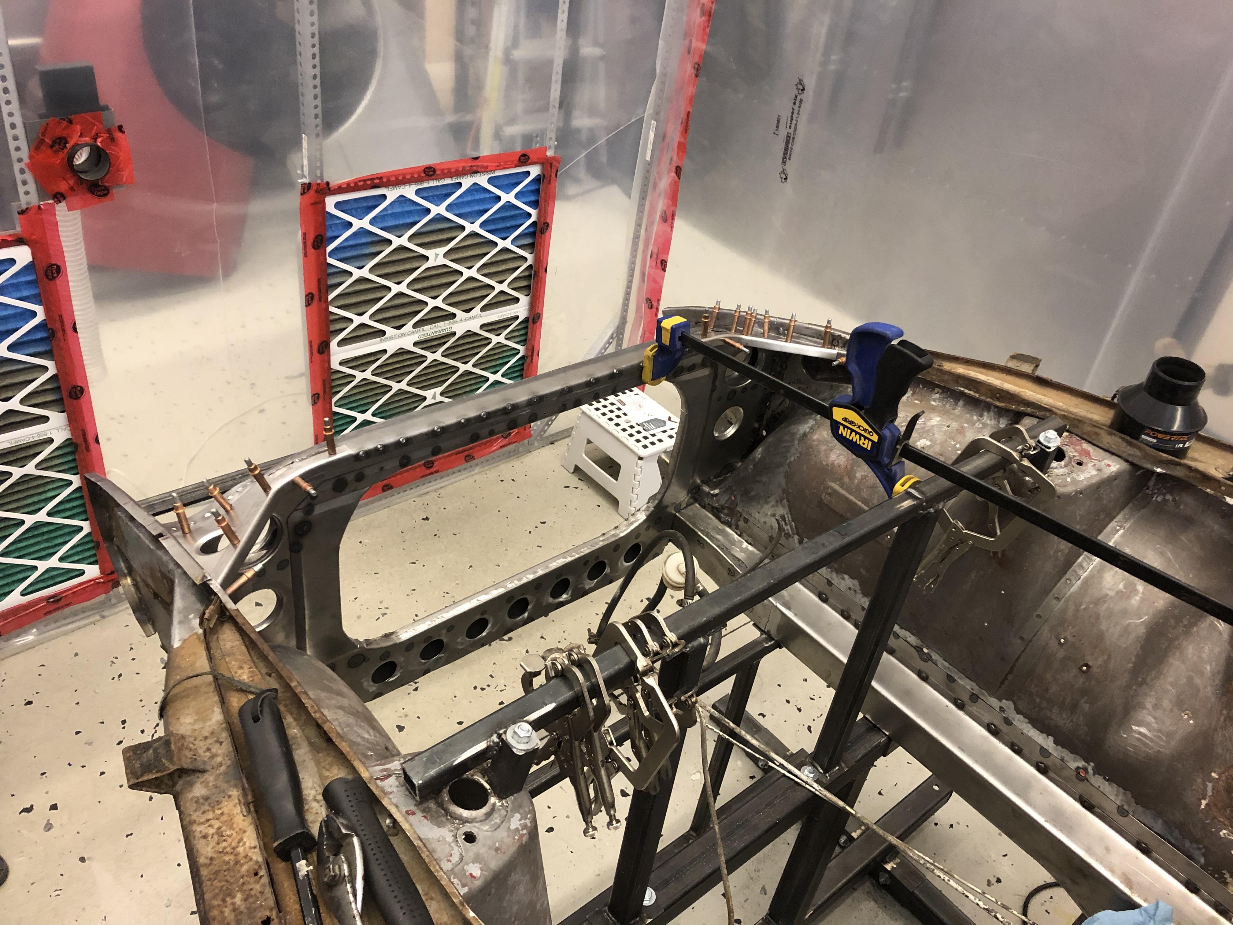
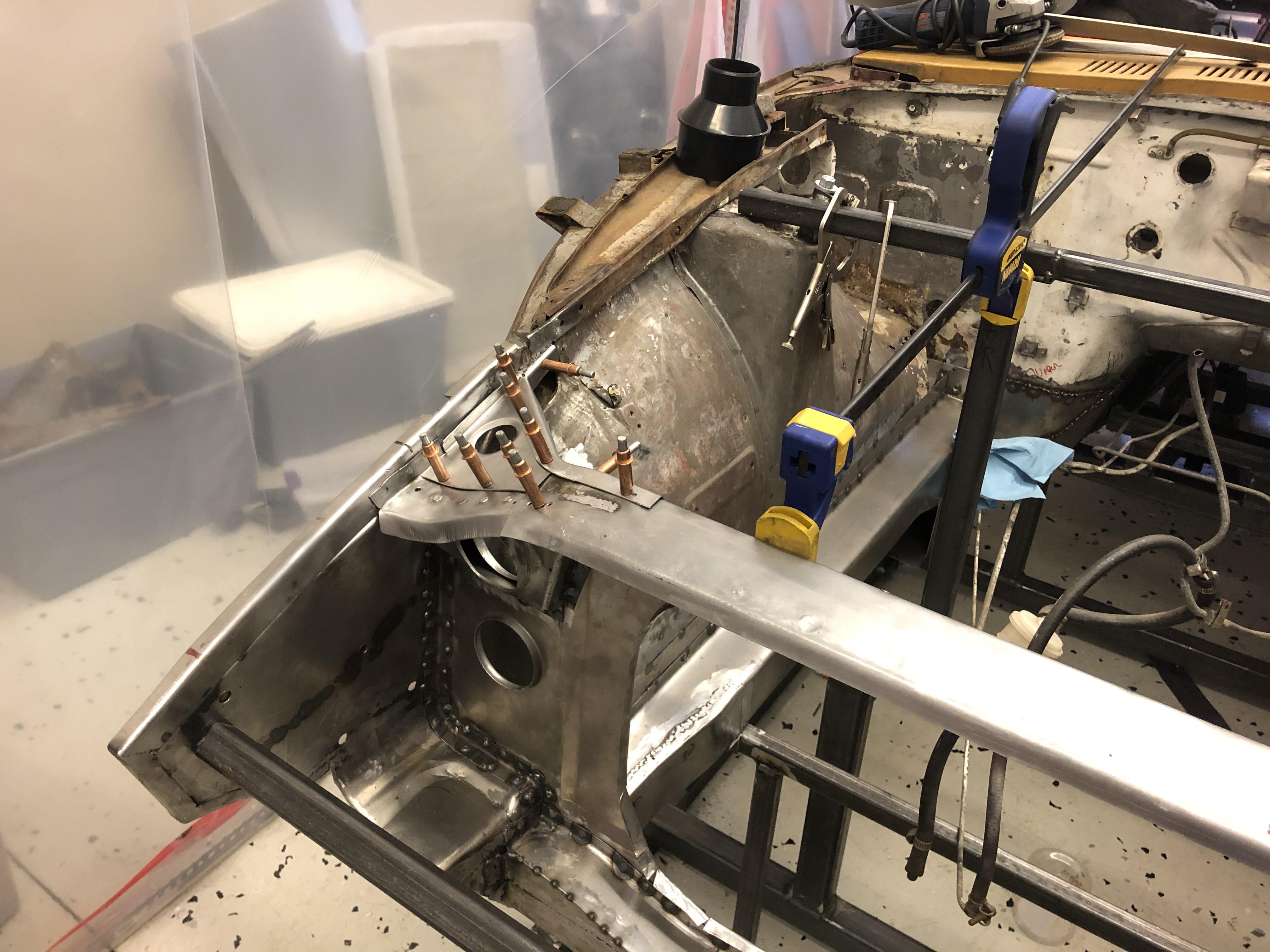
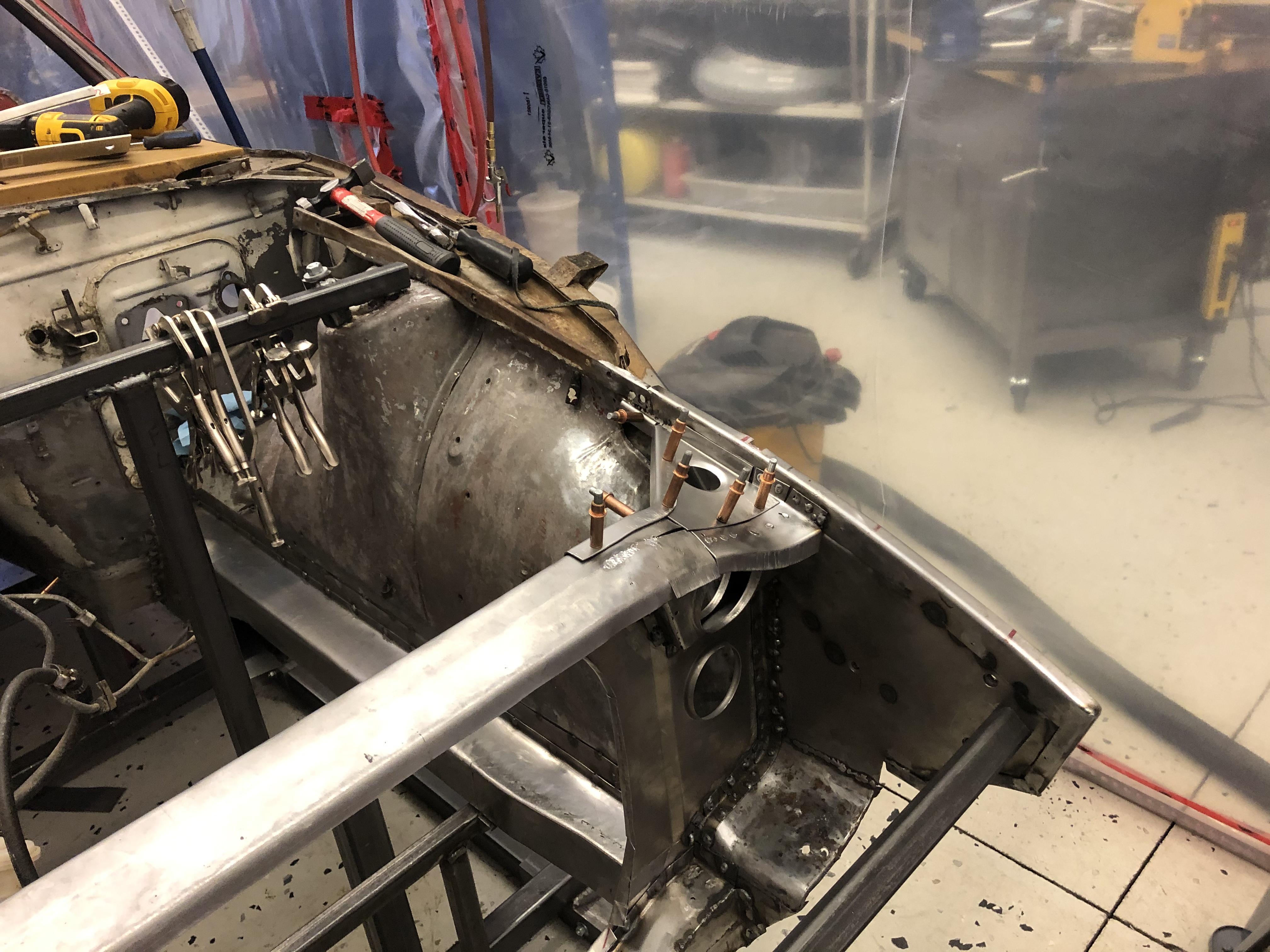
3 pointsAnd moved on to putting the final touches on the radiator support.... I welded the new rad support in some time ago but I wasn't happy with the upper brace ends so I cut them out and started over .... Went with dimples instead of beads, (for no particular reason?) Still need to some fitting, trimming and hammer/dolly work, but I am happier with the direction this is going ....


 3 points
 -
2 pointsGot a replacement on its way from Ebay $39. Sent from my iPhone using Tapatalk2 points
-
2 pointsWith the hands of a surgeon! I'm affraid I have the hands of a drunk stone mason. Great job Sir!2 points
-
To me the whole "ambiance" inside the cabin is what matters. That includes all switches and knobs looking good and working properly, including the radio. I really don't mind if the radio was repaired with old or new technology as long as it looks era correct, but the best sound possible it emits is truly appreciated.2 points
-
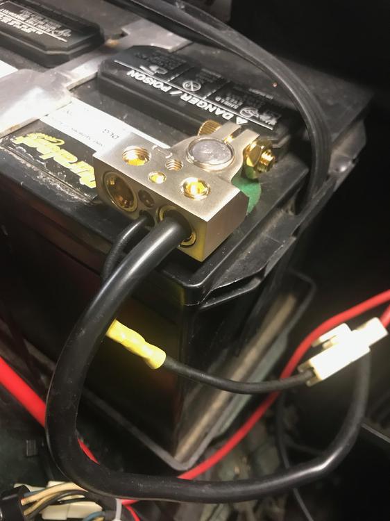
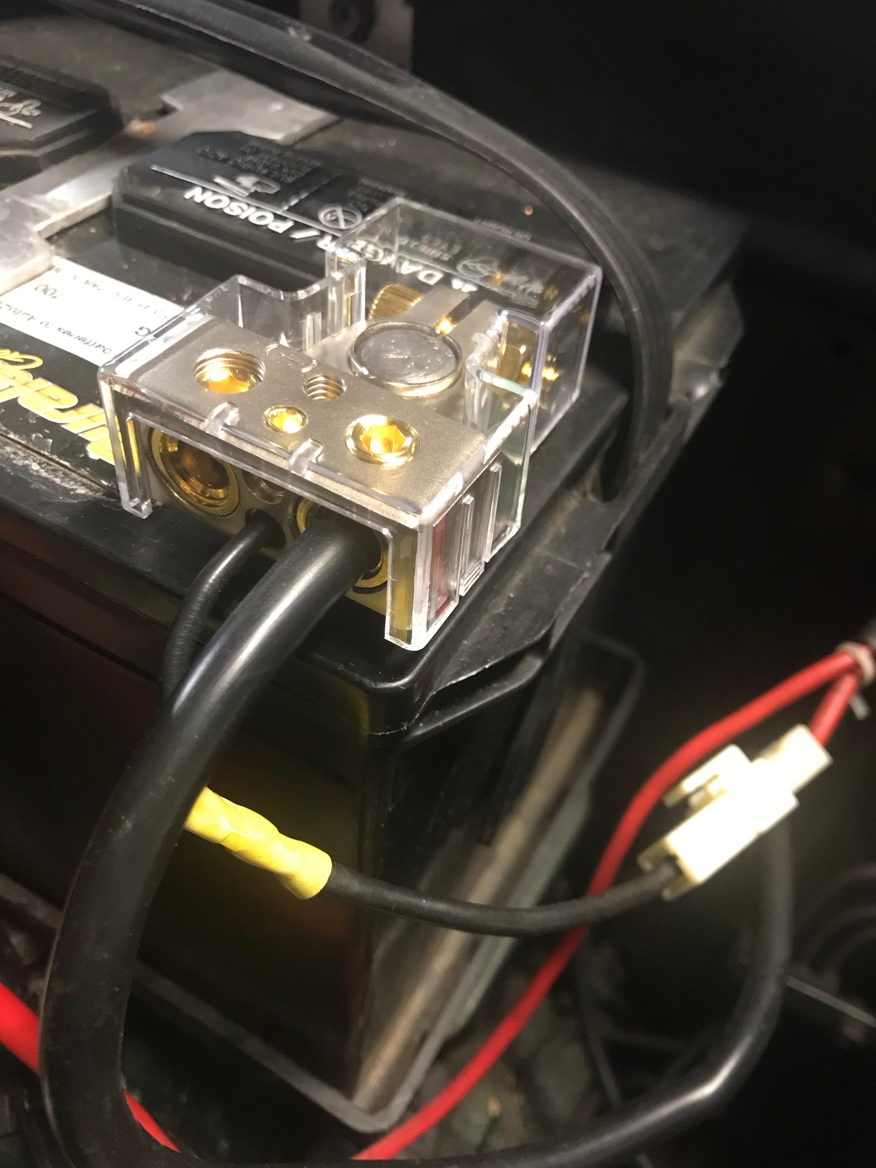
Battery Bling! Finally got around to installing new battery terminals that have sat around about 4 months. I like the way they look and will be great for the eye candy part of car shows but the functionality will require more effort. Instead of just a 1/2" (13mm) wrench, I'll have to add a full set of Hex keys and a 9/16" to the tool carry kit. The plastic covers look good too but there's Nooo Waay that I will ever let an Autozone guy replace the battery without me removing them first.

 2 points
 -
2 points
-
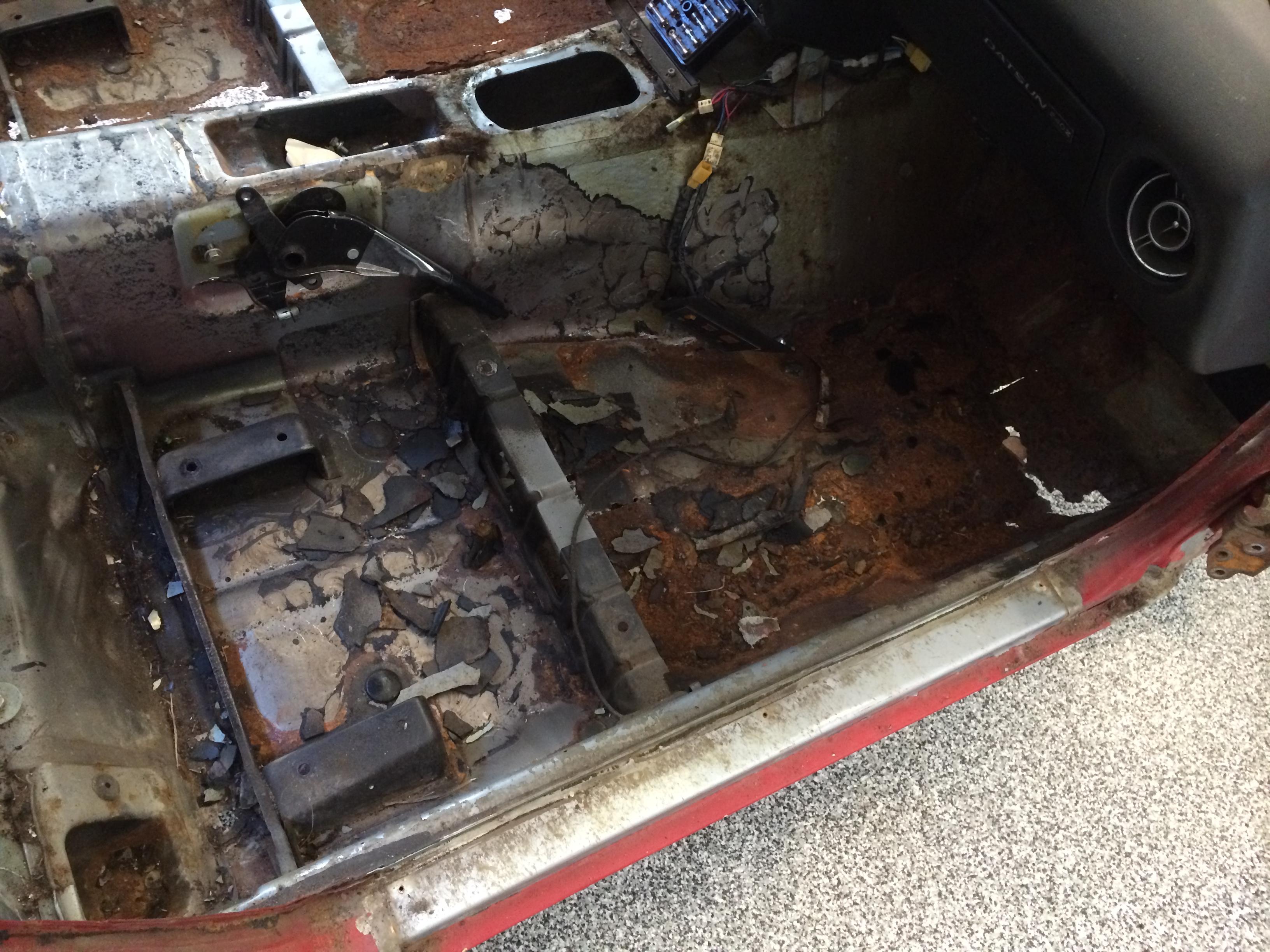
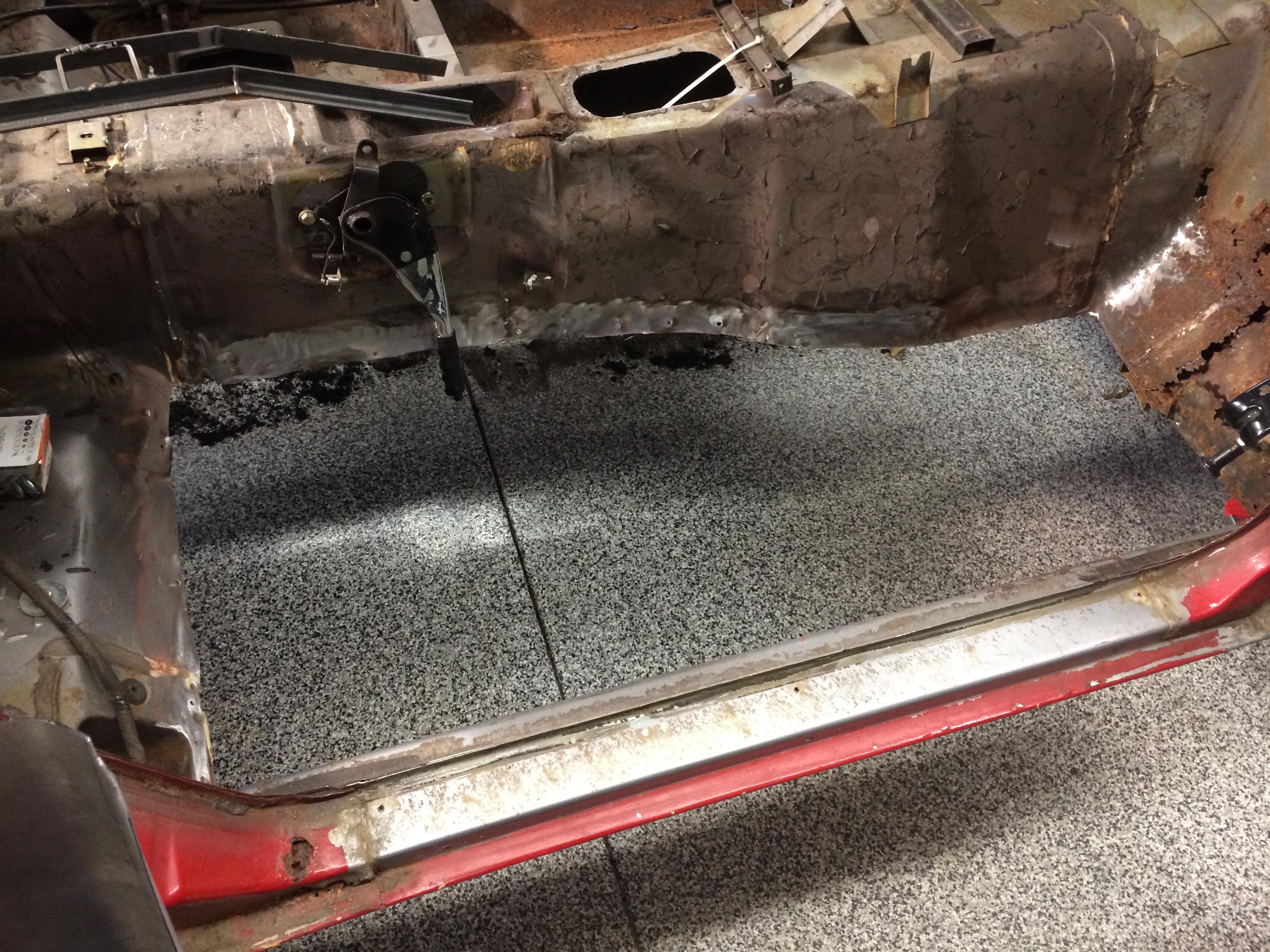
2 pointsLong time coming...got new floors, new inner and outer rockers, and lower firewall repaired! before pics ....
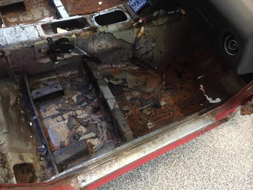


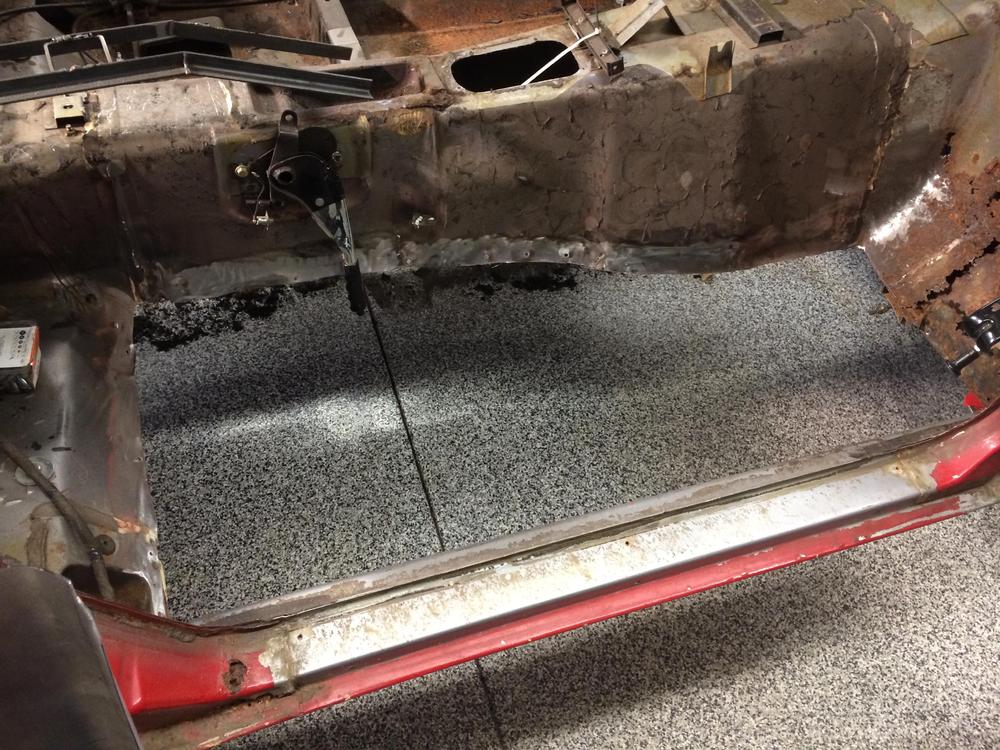 2 points
 -
2 pointsSo...half the job is done. I was able to completely ream out the hose with a wire brush on an extension. Got most everything out from inside I think. I'm sure it's 100% functional again. Now to repaint it Hi Temp Silver, as it originally was. The more I inspect this hose, the more I believe it is factory original...primarily because of the preformed bends and the unique way one end of it is formed where it attaches to the crankcase pipe. You can clearly see where it was manufactured with a pronounced expansion at that end to accommodate the larger opening of that fitting. Thanks for all the advice....once again!
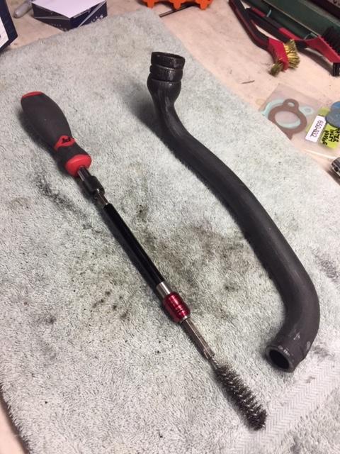 2 points
 -
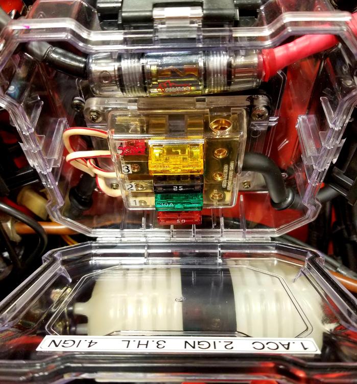
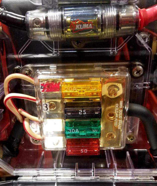
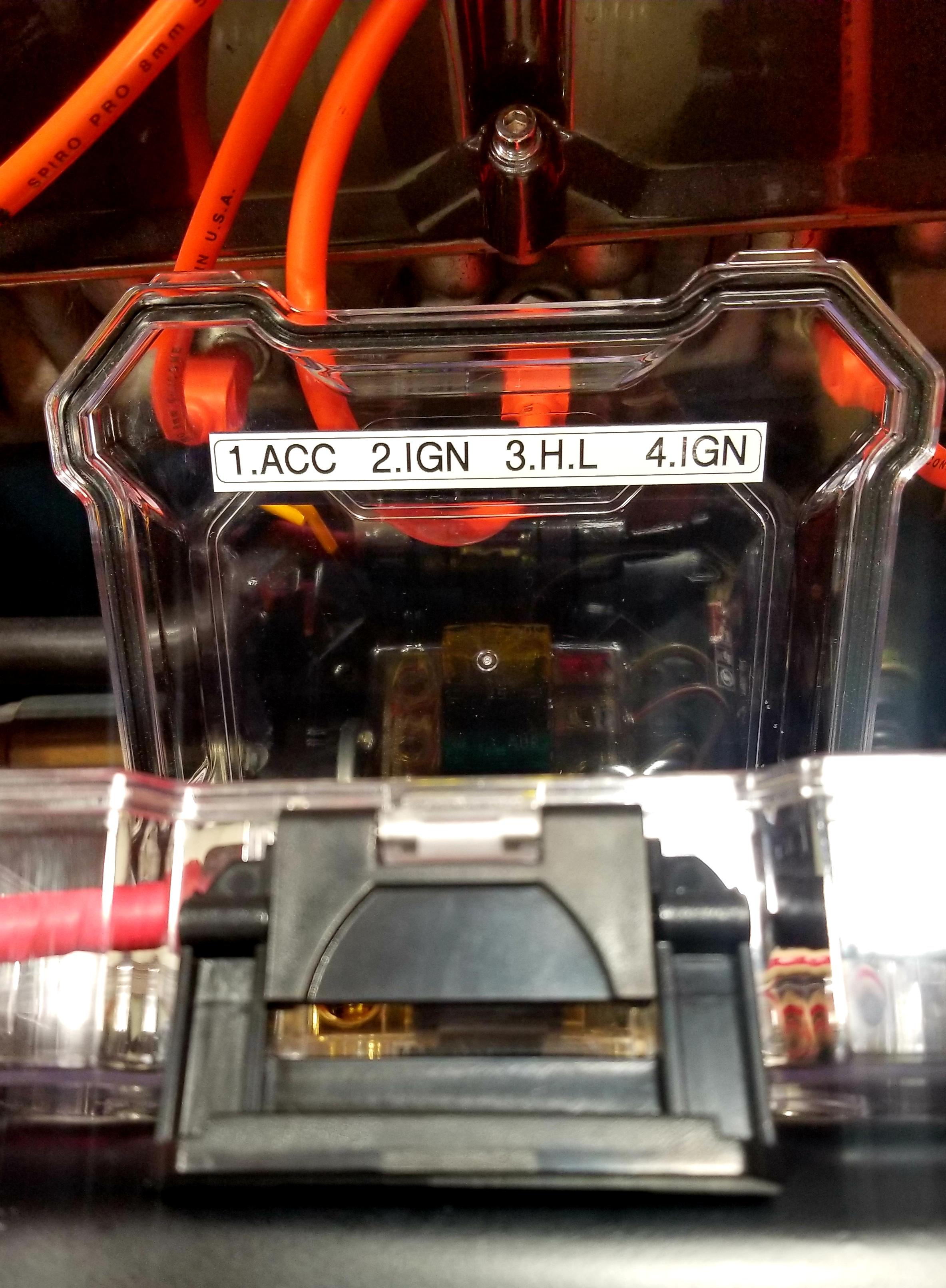
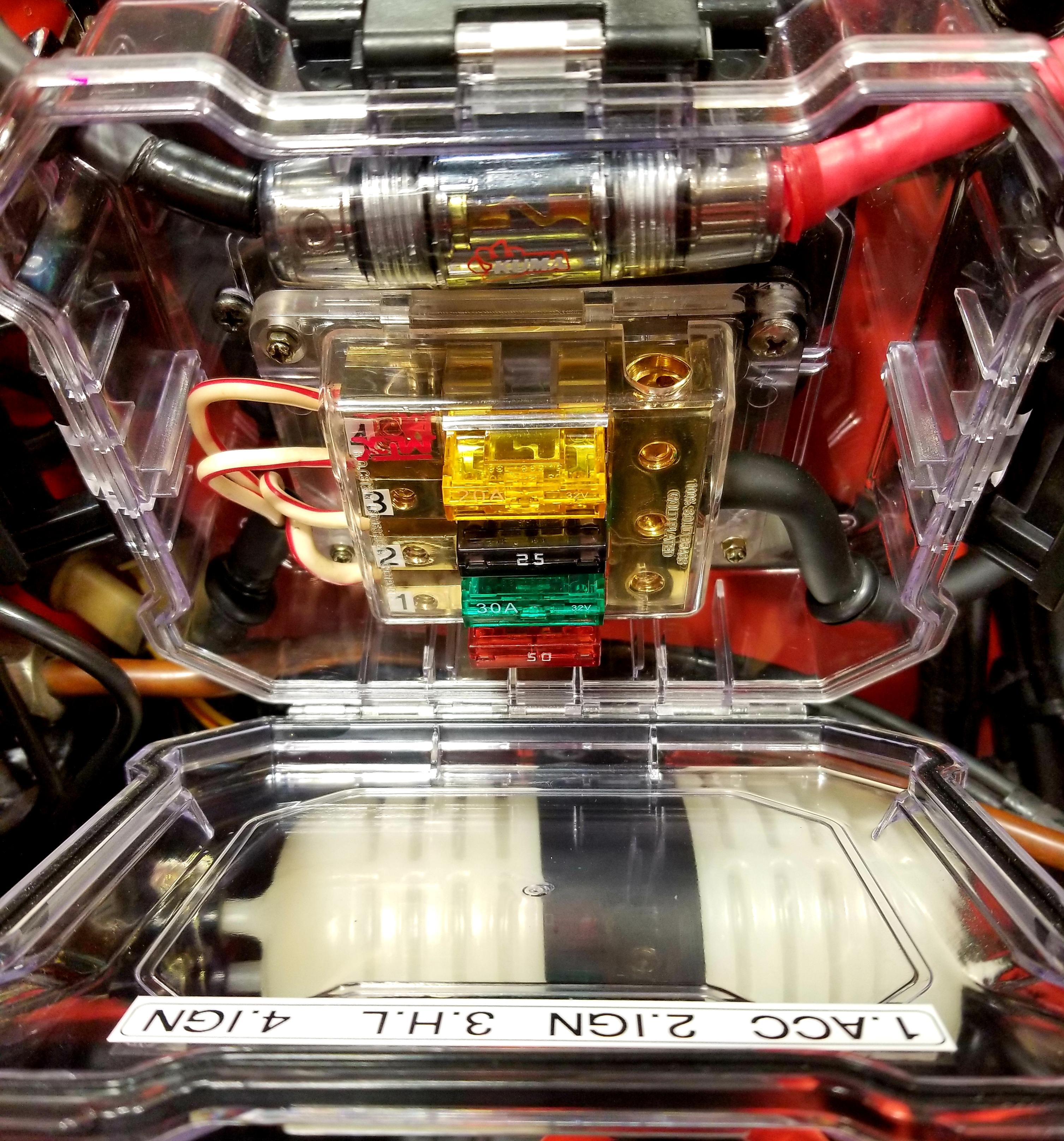
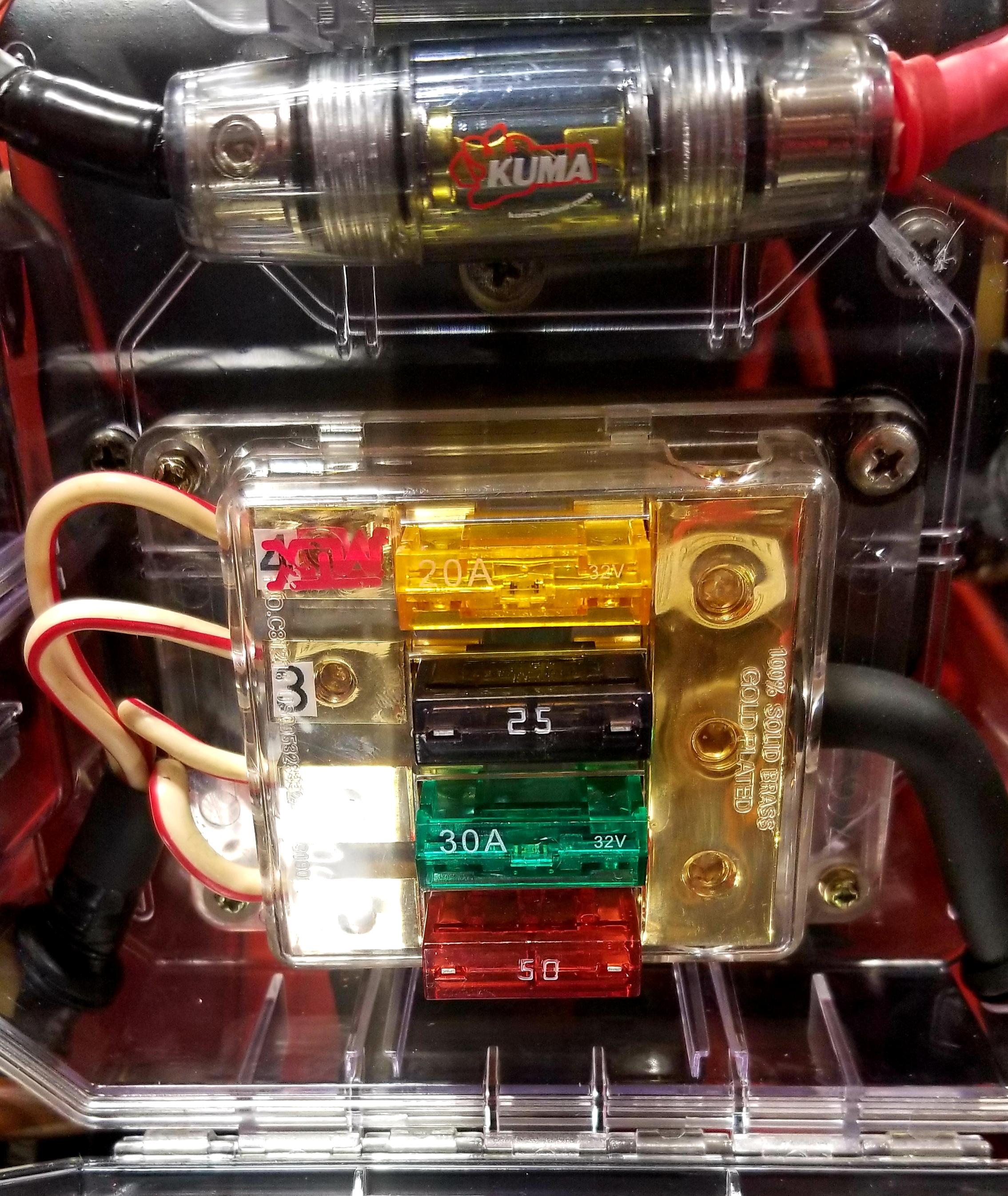
I was committed to updating the information pertaining the amp rating for the Maxifuses I used in the fuse block that replaced the fusible links but I'm embarrassed to admit I can't locate that post. Moderator's help in properly placing this update will be appreciated. Anyhow, here's the update. I have been running this set-up (pics below) for a couple of months without issues. The consensus was to decrease the amp rating of the fuses used as much as was logically possible to test how well they protected each circuit. I've made a point of driving with as much electrical draw as possible with the AC, headlights, sound system, turn signals when necessary, hazard lights and horn when possible. The only system I haven't used simultaneously is the windshield wipers/washer because I don't take the car out in the rain. The circuits have been identified on the decal on the inside of the case cover. Despite the information on the Atlantic Z page regarding amp ratings for the different color fusible links, my current (no pun intended) set-up is much lower and, as stated previously, seems to be working well. Circuit 1 (ACC): 50 amps, Circuit 2 (IGN): 30 amps, Circuit 3 (H.L.) 25 amps, Circuit 4 (IGN) 20 amps

 1 point
 -
Matters to me since I like to keep it original for reasons that I had this same car as a teen new, and just want it the same now. That and I really don't care if the quality is not up to todays standards since I don't listen to music much while driving, I prefer the sound of the engine. For music I have my Fisher 400/HH Scott/Sansui 8080 etc...1 point
-
 1 point
 -
1 pointThat is the part that can really get on my nerves. you just have to accept that's what it takes to get it right.1 point
-
1 pointYup - love me some Clecos! One thing that doesn't get discussed often: how many times does a part get attached/detached/re-attached before it gets welded in place? I might be slow, but I probably average 6 - 10 cycles, maybe more ....1 point
-
1 point
-
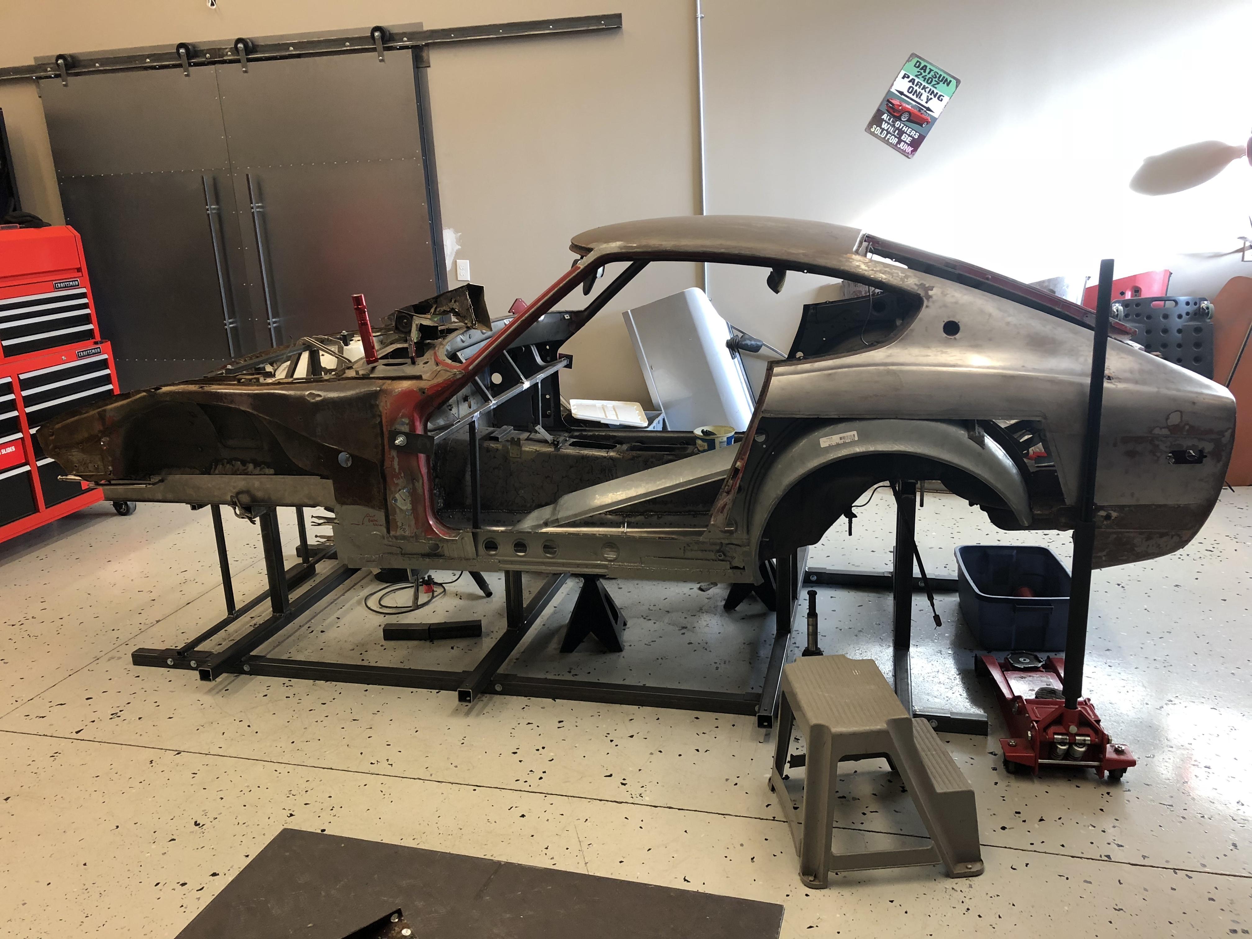
1 pointThanks guys! I appreciate the feedback. I know everyone prefers a “clean” car but here in the frozen north, so many of these cars have simply rotted away. Salvaging this car has been a challenge that I probably wouldn’t have started knowing what I do now.... but where’s the fun in that? I’ll be glad when it’s done. Then I’ll look at the roadster....1 point
-
Oh I think you are right! My faith in his bodyman has been restored? I just saw how shiny they were and assumed they aluminum rivets, using zip screws is exactly how I do it too. Need new glasses.1 point
-
1 pointWe can't all afford or get the opportunity to purchase a perfect example as our starting point, but I believe bringing back a neglected or abused Z is a much greater achievement than starting with a cream puff.1 point
-
Passenger footrest was standard equipment on 'DELUXE' models in Japan, and an extra-cost showroom order option on 'STANDARD' models.1 point
-
The foot rests were standard items on JDM cars. My 1972, FZ-L has it. Note that the floor has reinforcing where it bolts through.
 1 point
 -
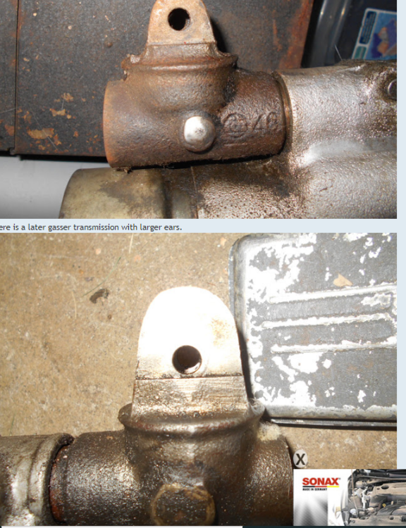
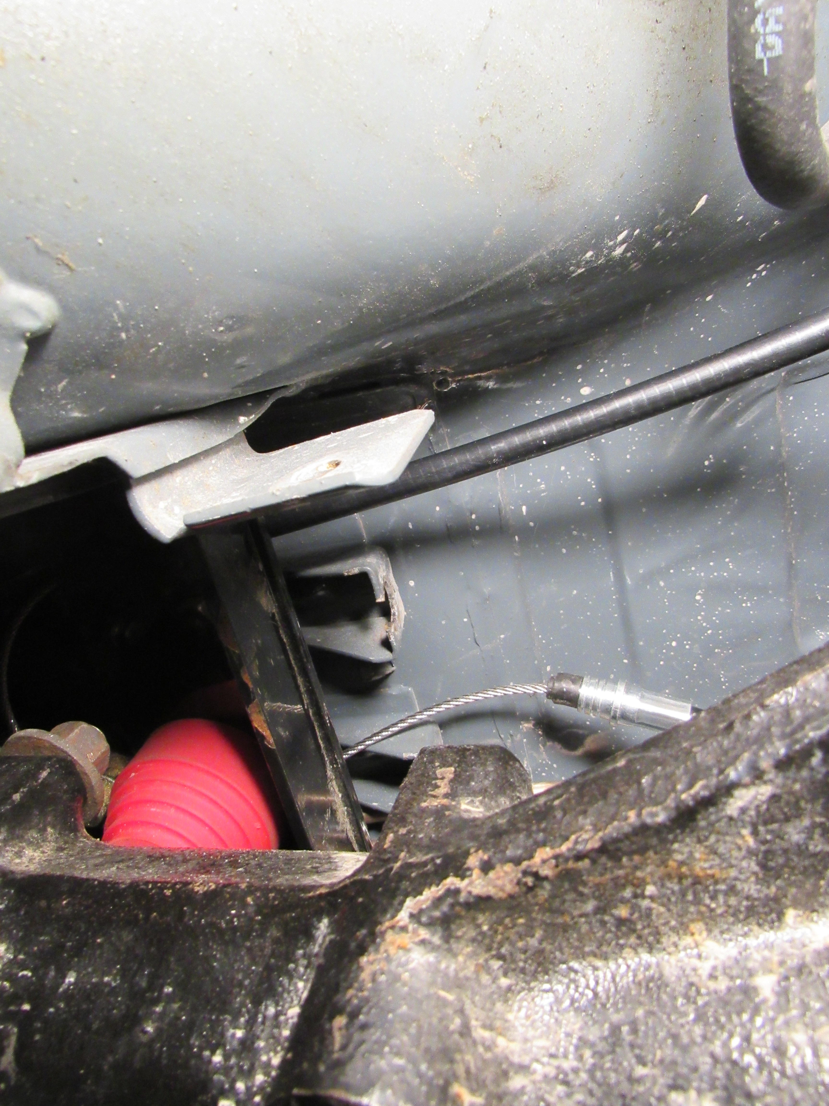
Looks like it might be a rivet. I'll bet you could grind the head off of it and the end would come off. Nissan never planned for this much disassembly, I'll bet, Might be some good stuff in the thread I found when I was looking for the picture. https://forums.nicoclub.com/transmission-stuck-in-first-gear-but-shifter-is-in-neutral-t602912.html
 1 point
 -
1 point
-
Removing that. Wedge bolt is a trick indeed. Best way is to drill a 21/64” (will explain in a minute) in the case to the left of the pin (in the picture) so that you insert a punch and drive it out. Use heat on the pin area to help break it free. You also have to support the outer end of the rod so when you hit the bolt with the punch, it doesn’t just flex the rod. Chunk of wood between rod and case will do it. Then tap that hole for 1/8NPT and plug it. Guess what size hole is needed for 1/8NPT tapping...1 point
-
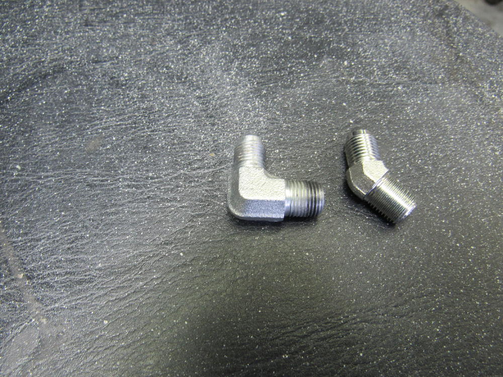
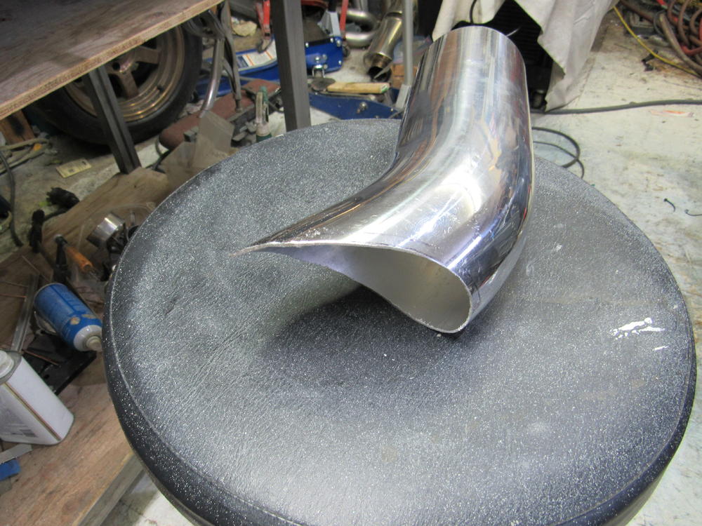
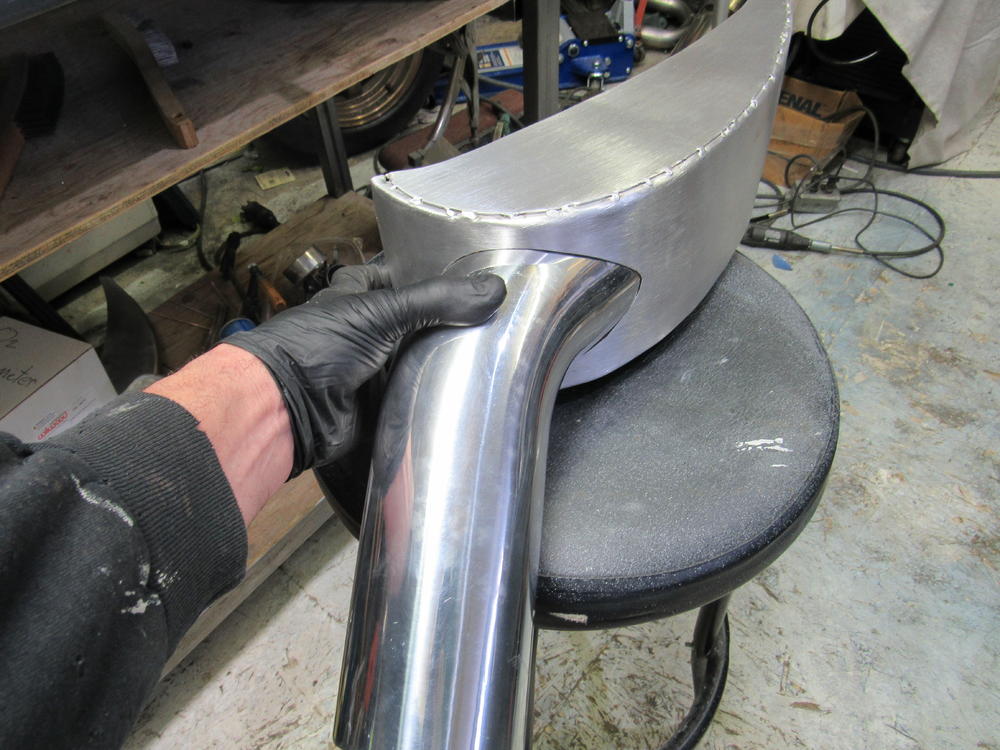
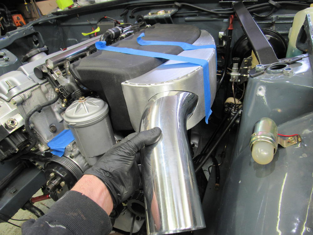
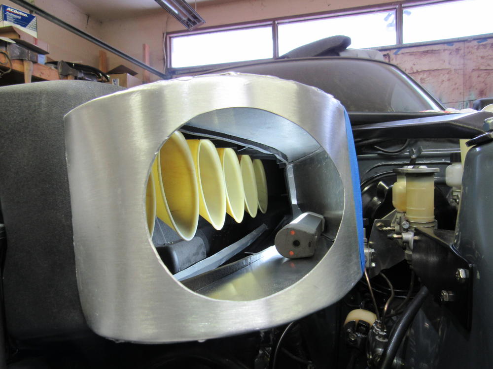
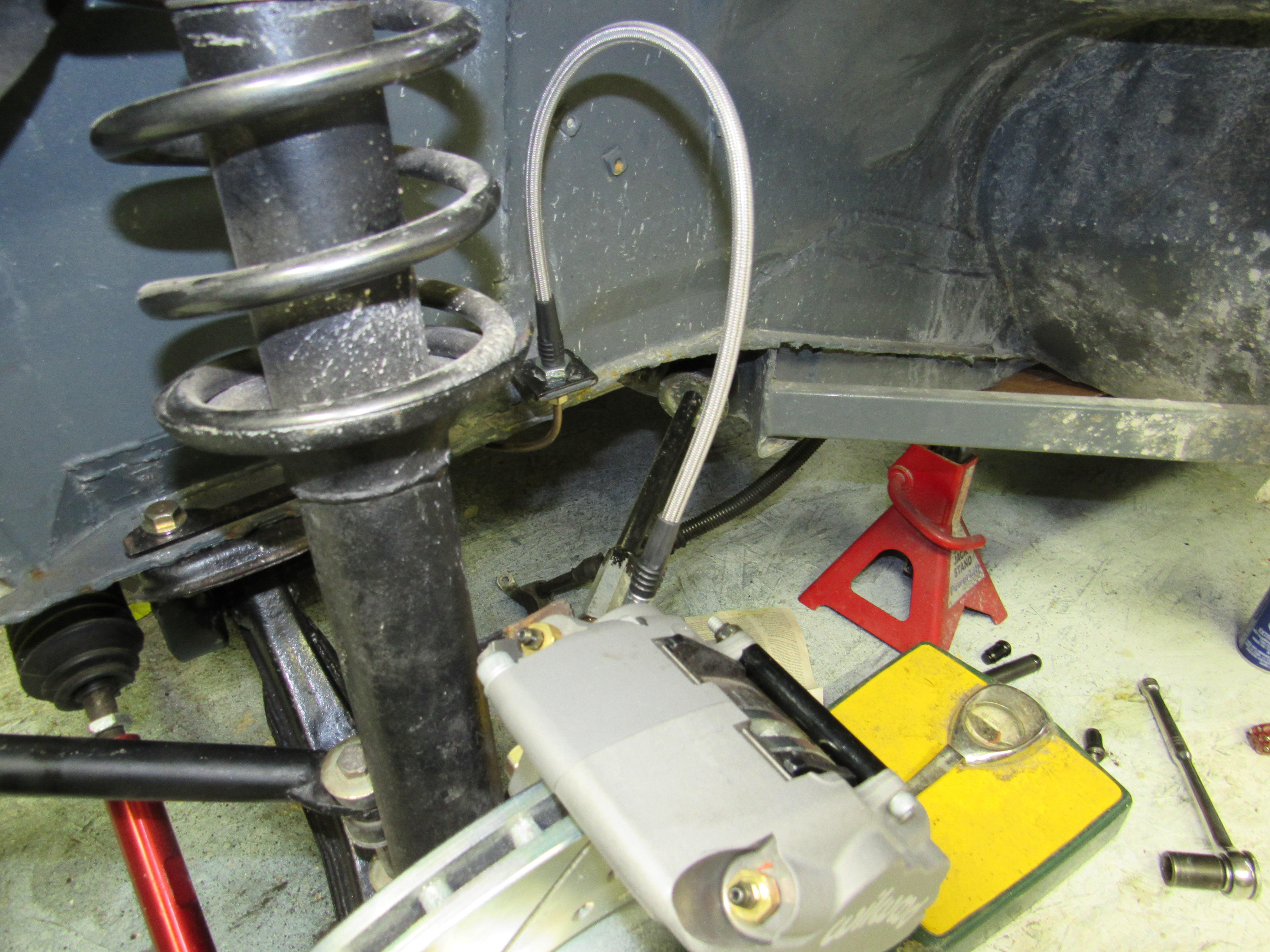
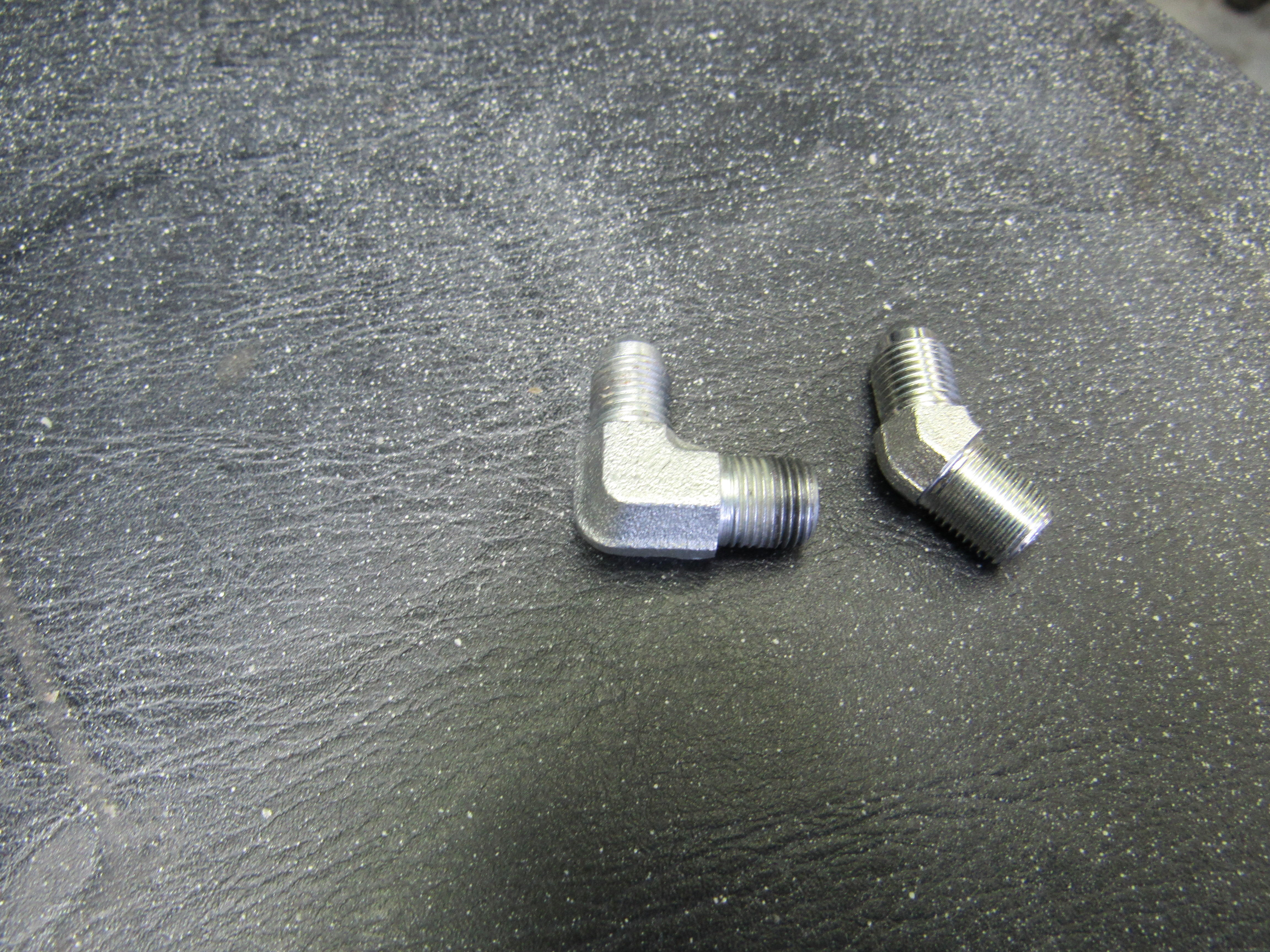
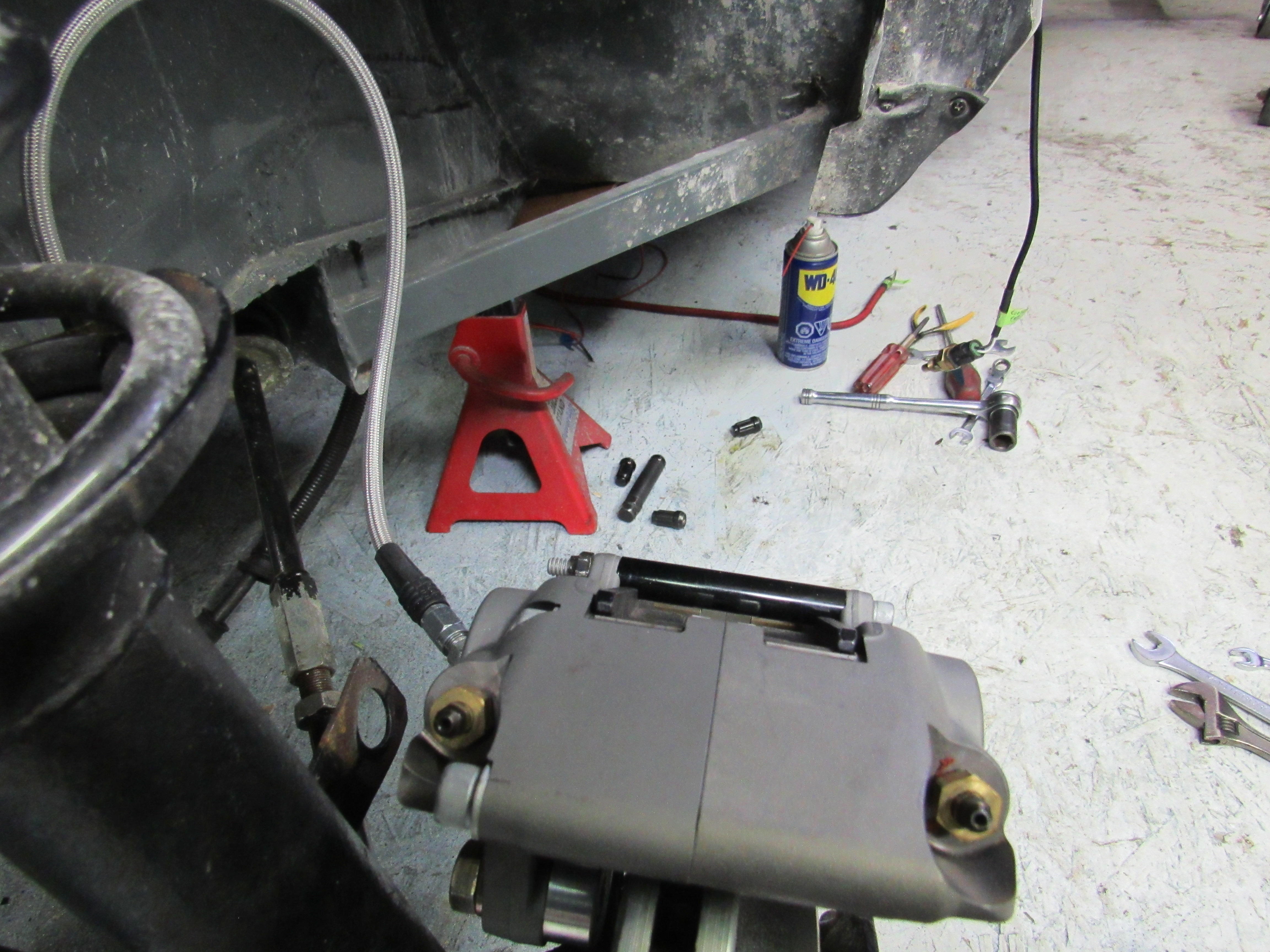
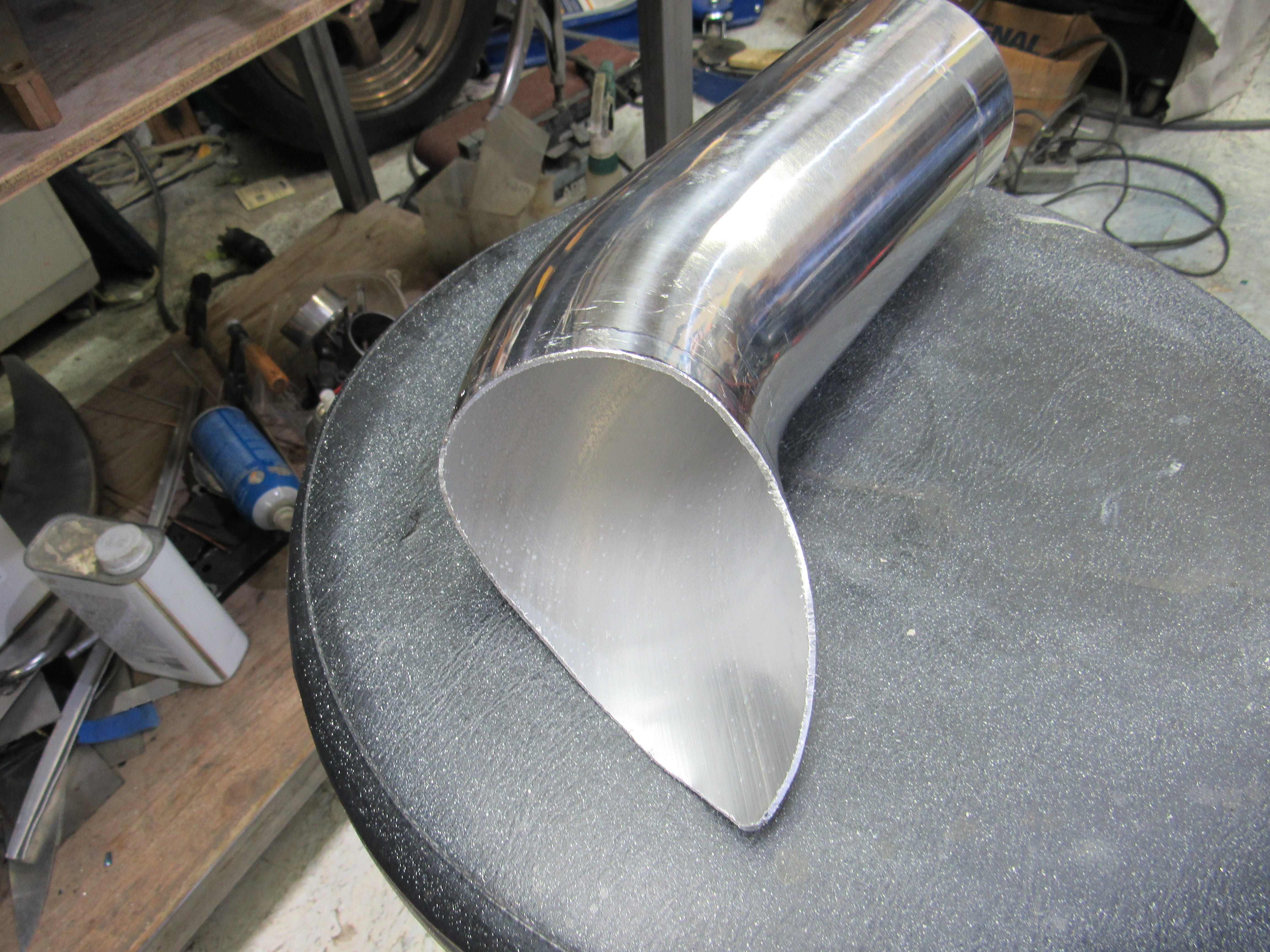
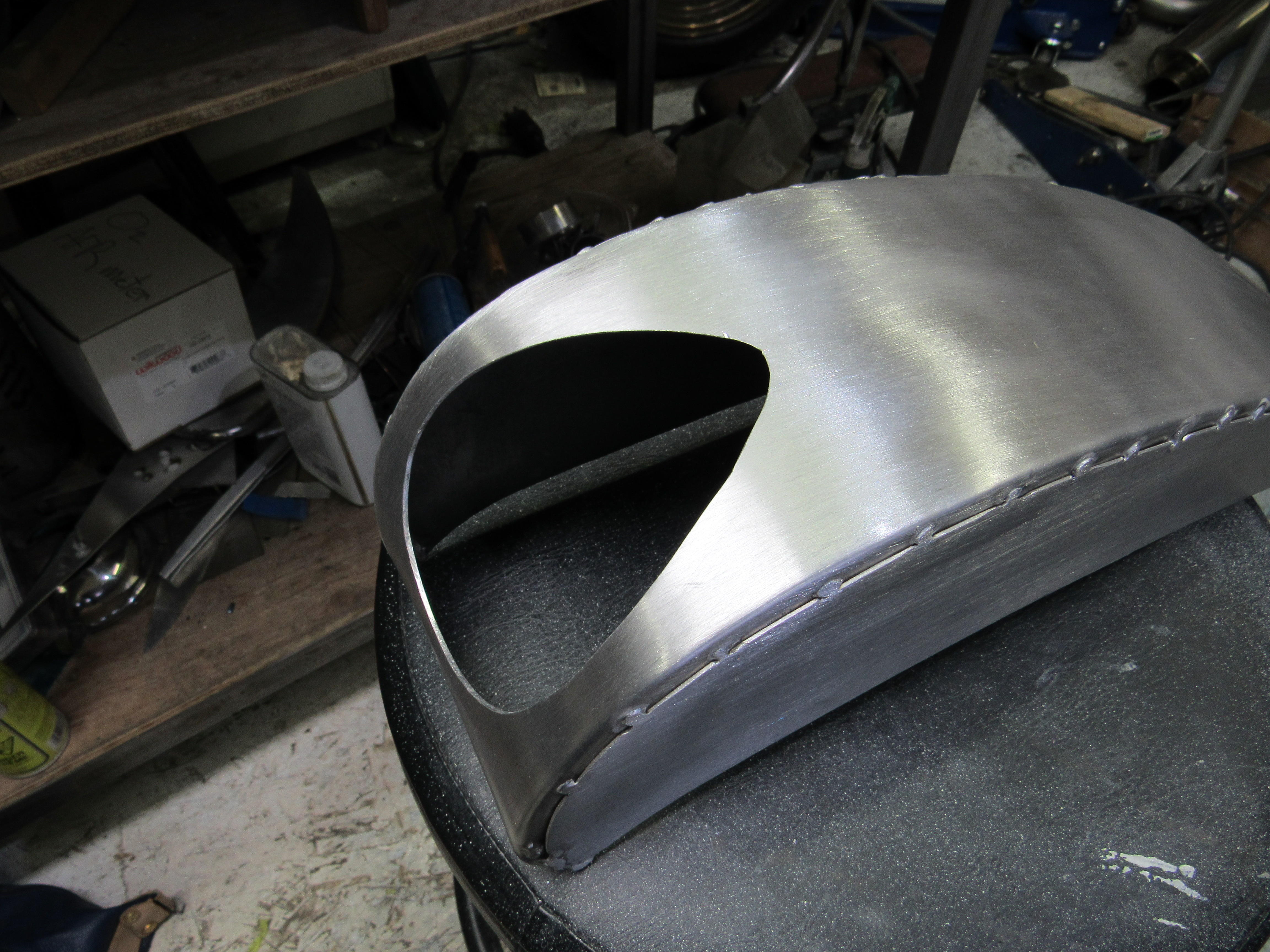
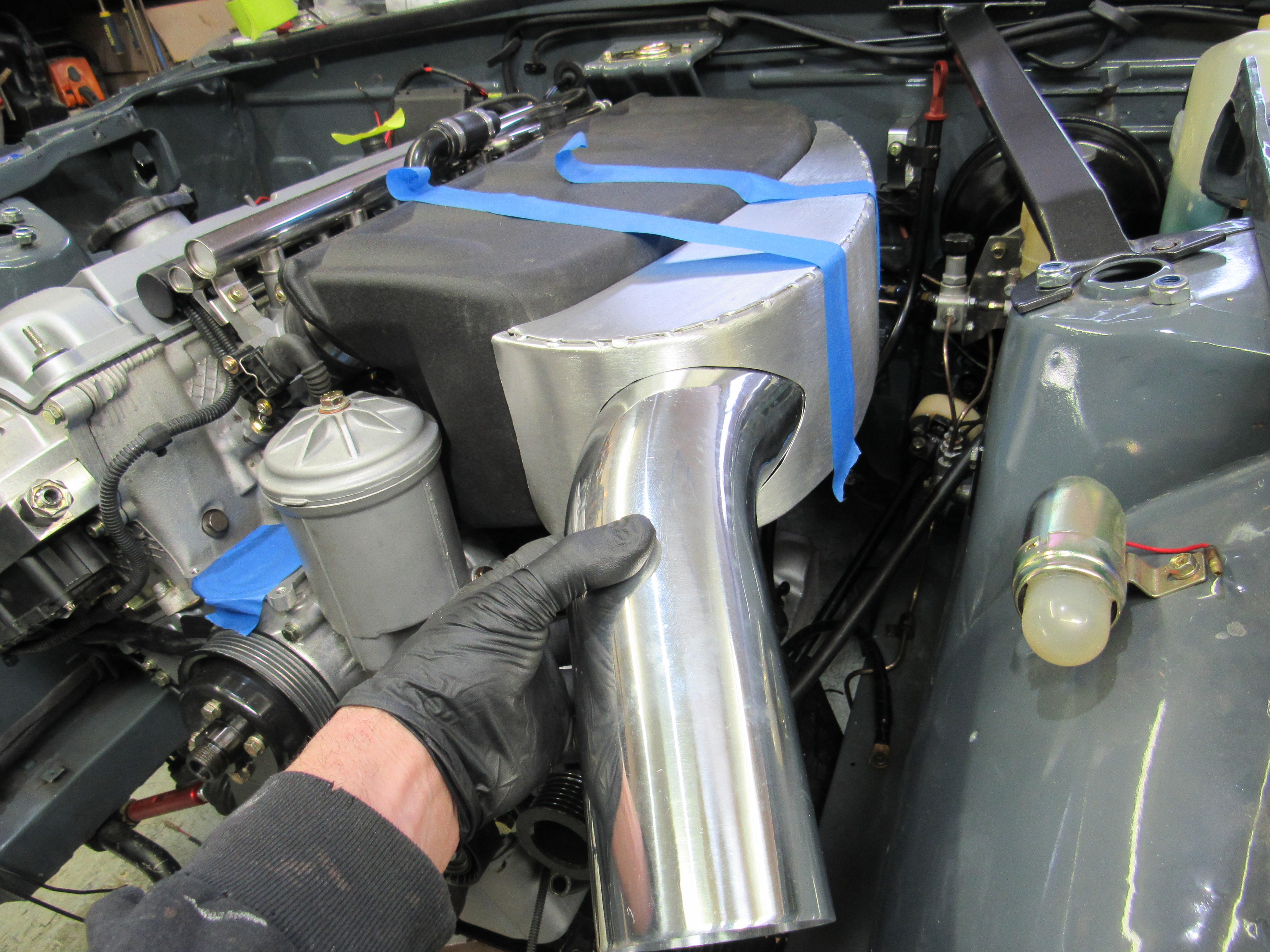
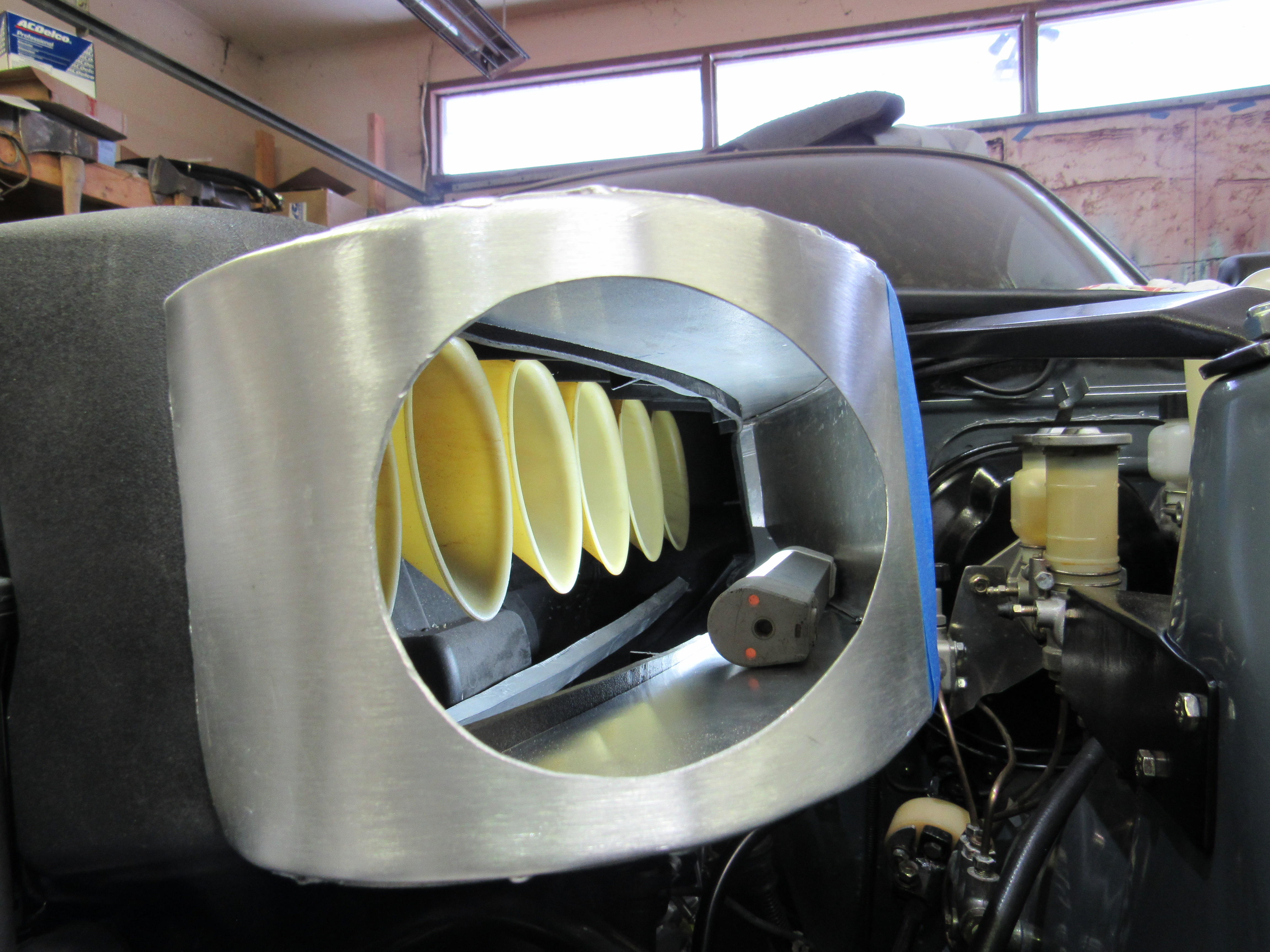
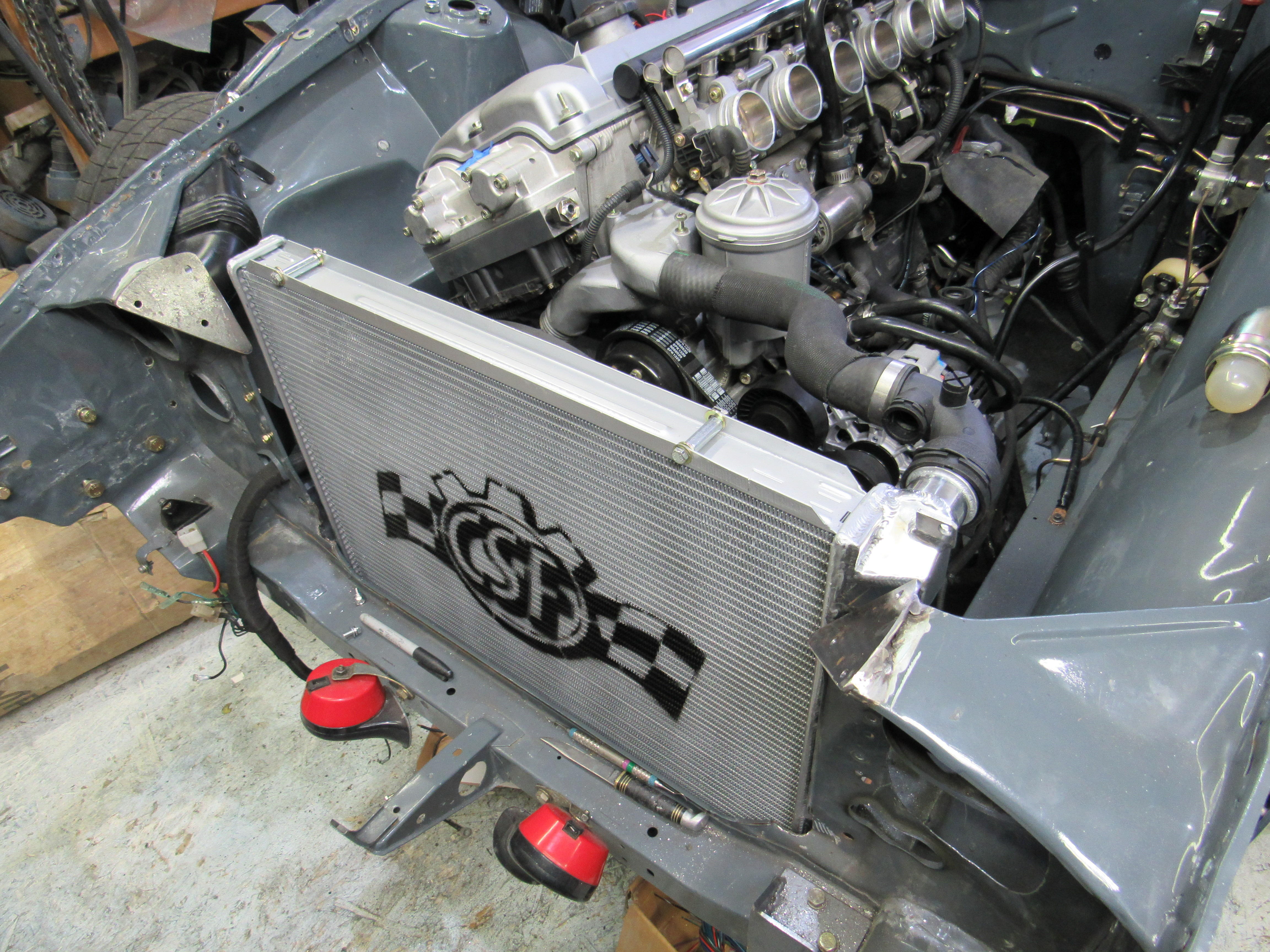
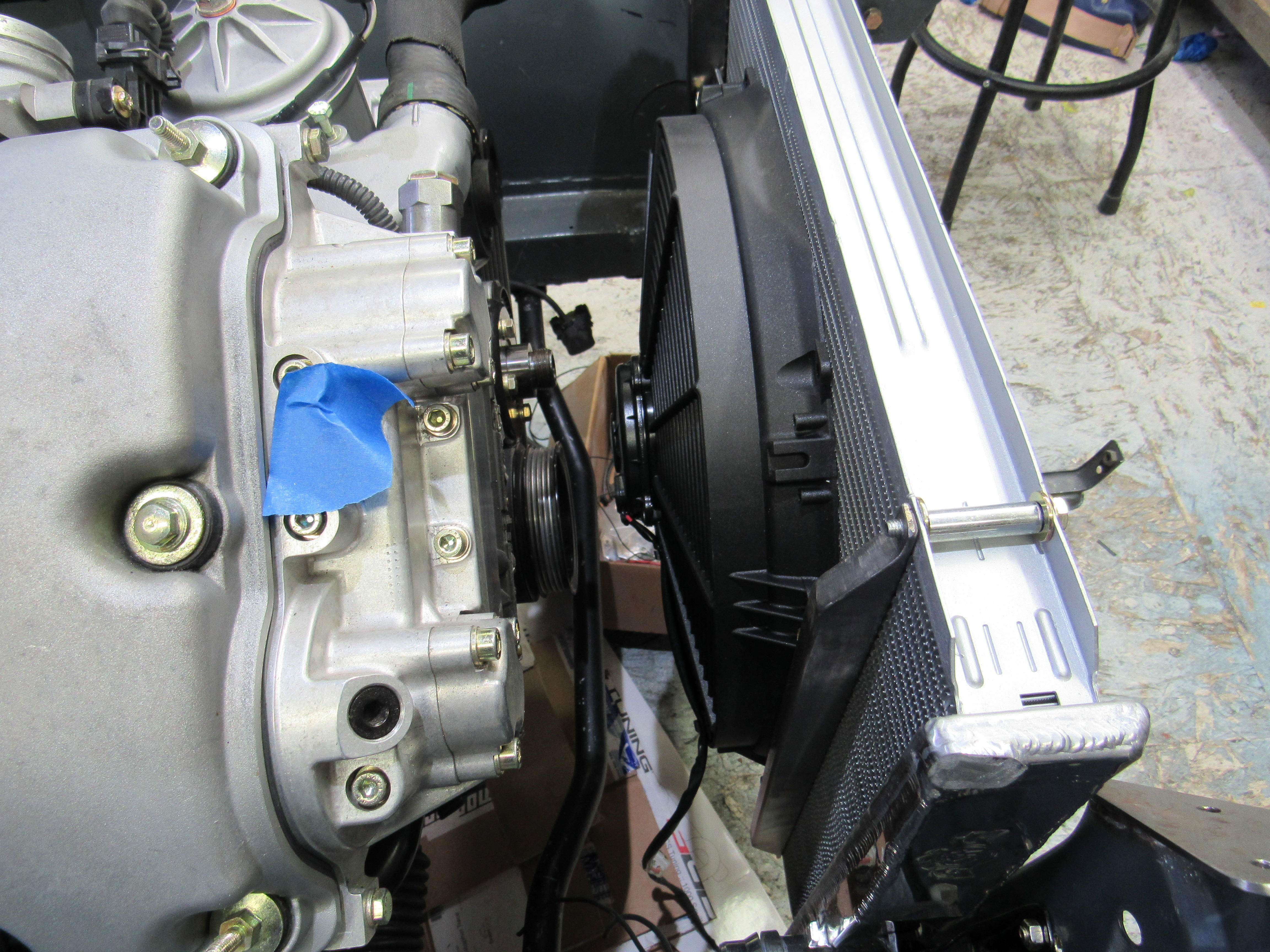
1 point1 point1 pointNothing huge to show you, but i got another update from my Bodyshop guy. The area behind the passenger seat got formed out of a piece of sheetmetal and installed. ready to weld in all of that stuff, including the floorpan.1 pointThings are moving along, the Silvermine brake kit is in, it certainly isn't a "couple of hour" job as stated on the site. That's because most of the fitment problems have been figured out but not all of them, it took me the better part of 2 days to install. First the bad, there is no written instructions, some random photos that aren't very specific of the steps required and a video where every time the instructor runs into a problem that part is edited out. If the adapter plates were stamped left/right, inward/outward that would have save me many hours but the worst problem occurs when you are on your back under the car fitting the new parking brake cable into place. The stock collar on the car that holds the cable in place has a ID of .475", the matching insert on the new cable is .500" so with the Diff and Diff mount in the way you have to try and get a large chisel or screw driver up there try and open that collar up enough for the cable insert to slide in. ? That's a problem that is so simple to remedy while the cable is being made. And one more, the two 90 degree elbow fittings for the flex hose runs the hose too close to the tire that it rubs so I had to buy two 45 degree elbows from Wilwood finish the install. This could be a great kit if those few problems were sorted before it went out the door, but Wilwood puts out an awesome product, I can't wait to see how this kit effects the stopping distance. I'm still fooling around with the fresh air intake and trying to make it work, I have sent it off to Ben to finish off the welds and make them pretty and the new radiator and Spal fan arrived so it is starting to look like an engine bay again.


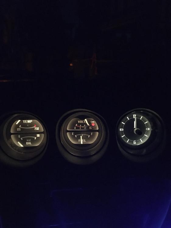
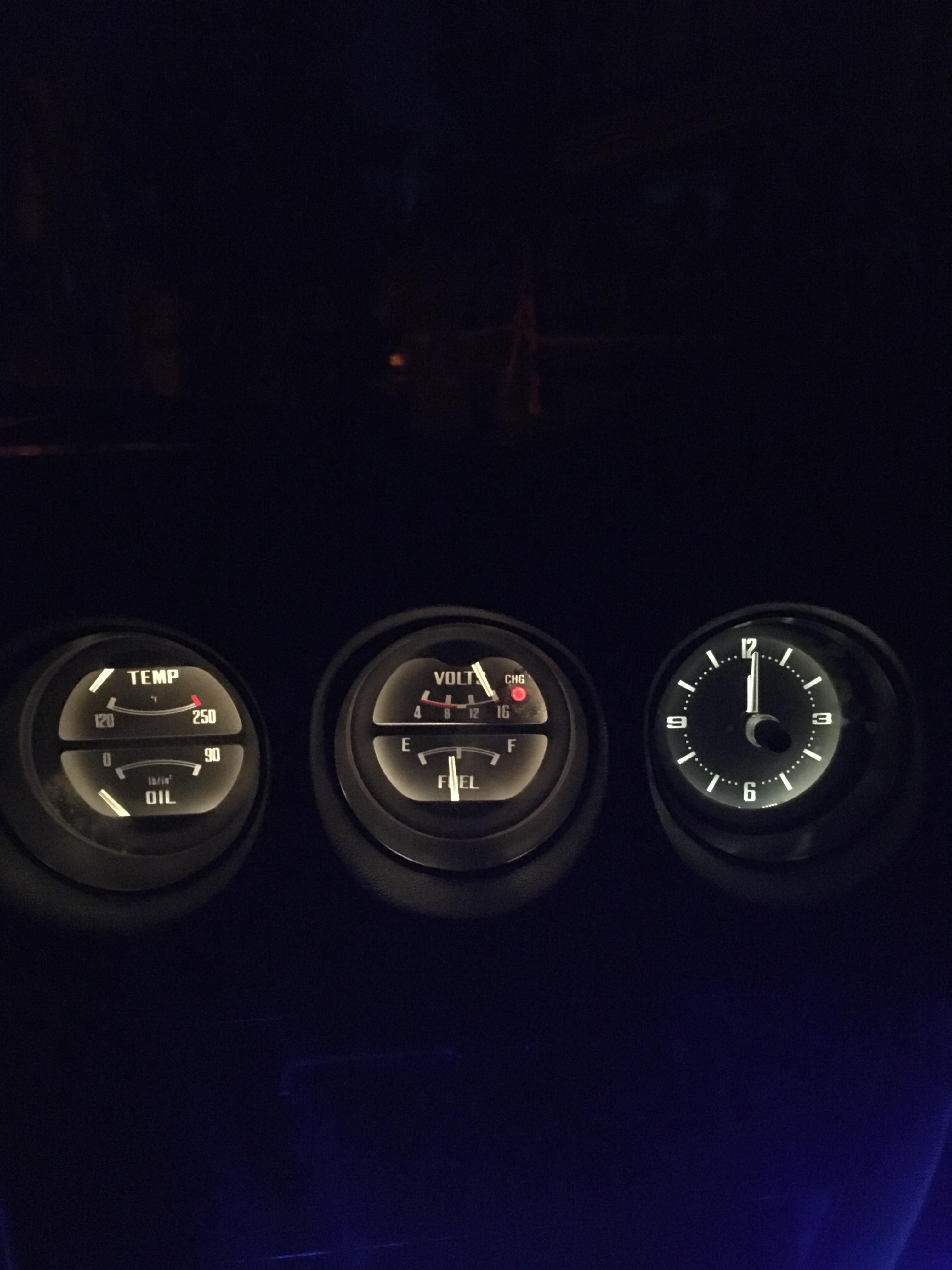
 1 point1 point2 Days ago my voltage regulator went out, producing an overvoltage and blowing all the lights that were on in my car except the headlights.Yesterday i started on the dash lights first and removed all the gauges and disassembled them, I took out all the green light filters and replaced all the bulbs and this was the end result. Much brighter gauges and A LOT easier to see now! EDIT: Ignore the oil gauge ( I have run a oil line into the car to a mechanical gauge to get a better reading as replacing the oil sending unit last year ended up saying no oil pressure on the stock gauge)
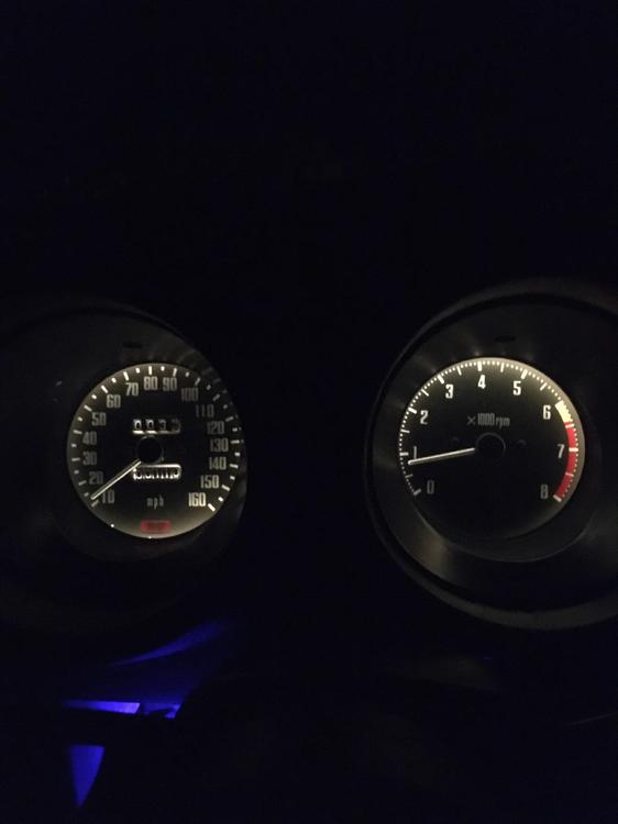
 1 pointYet he offers "30 day money back guarantee", so he'll refund your money we're to beleive but he just doesn't want the junk back?1 pointMy Hitachi AM/FM is gutless, only picks up a few stations, and drifts away from the stations it gets. I'm planning to swap in a new radio but would rather keep it looking stock. So hell yes I'd do that.1 pointIf you are not entered in a Concours d'Elegance event, why should it matter?1 point1 pointSo I just bought my first Z (Yay!) and it had the same lock issue, along with a bunch of other ones. A slightly different solution worked for me, so I figured I'd share. Unfortunately, in all my excitement in getting it to work, I put everything back together before taking any pics, but will try to describe it best I can. My lock problem was as described in this and other threads. The lock cylinder looked exactly like the one pictured in this thread. I didn't have any metal wire which I would trust to retain its spring constant in the long run to make the "wire hanger" repair last. I did have some softer metal wire; one of those shiny steel types you see at hobby stores. So instead, I drilled a hole right in the location where the lock cylinder lever arm is worn down (where the metal used to be, but is now gone). Drilled straight in, perpendicular to the shaft, about 2mm deep. Then jammed a small length of wire into the whole and compressed it in there with pliers. Matched the drill bit and the wire size closely so the wire barely fit and, upon compression, the wire expanded in the hole and pretty much stayed there for good. Then file the excess wire down to resemble the original shape of the cylinder and done! If anyone wants more info, I can try to draw up some explanatory diagrams. (This probably makes a lot more sense to me than someone reading it) Hope this helps.1 point


Important Information
By using this site, you agree to our Privacy Policy and Guidelines. We have placed cookies on your device to help make this website better. You can adjust your cookie settings, otherwise we'll assume you're okay to continue.