Captain Obvious
Community Member
-
Joined
-
Last visited
Everything posted by Captain Obvious
-
The 74 cigarette lighter is illuminated the same way. And same to you all and hoping to see you all again at a future ZCON!!
-
I had one more thought about this appropriations bill thing and then I'm gonna go back to working on cars... I was wondering about the one side "using Covid as blackmail" thing to get stuff put into the bill other side didn't want. I found a copy of last years Consolidated Appropriations Act 2020. Last years version of the same big appropriations bill. Well guess what... That stuff did NOT get stuck in there with Covid. In fact, that other stuff was already IN there. The Covid relief stuff is new, but the rest of that stuff? Already there. Some of the numbers changed a little (presumably for inflation?), but the same language for the same things was already there. I found the first four items and stopped. I'm assuming the rest of them are all in there as well. So what's the point? The point is... It's the example of twisted misleading "semi-facts" that are being used to tell you what your opinion is. It sounds plausible or it wouldn't work. And it sounds like something terrible that one side forced on the other using Covid relief as blackmail, but in fact it was in there already. And it was approved before. The people who are complaining about these items now... They approved it last year, right? And they didn't flag it as a problem last year, right? And they've had a year to finish reading last years details, right? I didn't dig back further than last year, but I suspect much of that stuff goes back a number of years. Here's what I'm talking about: Makes me wonder why are they making such a stink about all of a sudden? Wasn't it just as much of a problem last year? Did they just get around to doing their job and reading it this year? Did someone suggest they could blame the other side for blackmail and nobody would actually read any of it and figure out that it's not true? Did someone above them tell them their opinion and now they're telling you yours? OK... I think I'm talked out. I think I'm gonna go machine something.

-
I wouldn't fault someone for saying "it's a Datsun color" or "it's an original color", but I would have a problem with someone saying "It's the original color" if they weren't sure. Far fetched example... All the remnants of the original have been removed. There's really no way to tell what it was. And Datsun didn't keep any records, so there's no way to check old documents. Seems like nobody would be able to prove one way or another. You paint it in an original Datsun color and don't get lucky and happen to accidently hit the color it was when it originally left the factory. But so what... Nobody would ever know for sure. Then you sell the car and a perspective buyer asks "Is it the original color?" You say "Yes." and the guy buys it. Then a week later he's at a car show with his new purchase and someone recognizes the car as being his old Z car "he bought new back in the seventies". And pulls out the old dog eared photo of the car back then. Wearing a different color. Far fetched? Of course. Possible? Of course. Fraud? Of course.
-
That's excellent. Love it!!
-
But seriously though, the way the large bills like that are done is a problem. Lots of pages, not enough time to dig down into the details, and people sticking things they want into it and saying "well if you want this other stuff, then you'll have to agree to this stuff too." It's an antique problem. For example... The stuff on the previous page that people are complaining about now has been around for a long time. I didn't read the whole thing, but it looks like most of it al stems from the Foreign Assistance Act of 1961. So it sounds to me like the people complaining about this stuff (now all of a sudden) have had about fifty years to read it and do something about it. They cherry pick plausible sounding sections and twist them to support their opinion and then tell you that you should agree with them. It has to be plausible sounding or it wouldn't work. It has to be close enough to the truth to sound good or it wouldn't work. But it's all twisted misleading facts. Alternate facts. Propaganda. Both sides do it. So I don't know what the answer is, but the first thing to do is to stop being told what your opinion is. Shut the sound on the TV off. I give more credence in what they're willing to put into print than what comes out of their mouths. There's still slant to one side or another there, but not as much as the words they speak. If they're confident enough in what they want to tell me, they'll write it down. And most important of all? Stop getting your opinion from people on twitter or facebook or websites.
-
!! Well if those are the my two choices, I'm much better at lurking in the background and saying bunches of words that in the end really mean nothing at all. I can say lots of stuff without ever being able to be pinned down on any of it. Kinda like Teflon. I can also interpret and defend pretty much anything. Your Highness is like a stream of bat wizz.
-
Forgot... All of the stuff highlighted as problematic on pages 1476 to 1500? All of that stuff is in the Department of State part about funds appropriated to the president. DIVISION K—DEPARTMENT OF STATE, FOREIGN OPERATIONS, AND RELATED PROGRAMS APPROPRIATIONS ACT, 2021 TITLE V - MULTILATERAL ASSISTANCE FUNDS APPROPRIATED TO THE PRESIDENT INTERNATIONAL ORGANIZATIONS AND PROGRAMS So for future reference... The Covid stuff starts on page 1815. So anything on prior pages is not part of the "Corona Virus Response And Relief" section of the document.
-
You have highlighted what I believe is the biggest part of the problem right now... The twisted, misleading misinterpretation of info fed to you by the people whispering sweet nothings in your ear in your own corner. They tell you what to believe, and how you should react to it. Did you actually read any of the bill? Did you actually read ANY of it, or are you simply accepting the summary of the people in the media (radio/TV/web ) and accepting their interpretation hook, line, and sinker? Why do I ask such a thing? Because the whole bill.... "This Act may be cited as the ‘‘Consolidated Appropriations Act, 2021’’ " is a far reaching budget bill that is mostly not about Covid at all. It's about a whole bunch of other stuff that was being voted on regardless of Covid. There are only two sections that pertain to Covid, and guess what... All of those page numbers you referenced above??? None of them are in the Covid relief sections at all. So all those people saying "Look at all the pork stuck in the Covid bill!!" Clearly haven't read it either. First of all, because it's not "the Covid bill", it's the "Consolidated Appropriations Act, 2021’’ , and second, All the parts someone told you that you shouldn't like aren't even in the Covid portion of the bill. What we need is more independent educated thought instead of having our opinions fed to us.
-
Short answer. No. Medium answer. No. How can your conscience even allow you to ask such a thing? Long answer: No. If you pick a factory looking color (just because you like it) for your respray and then find out later you got lucky and it WAS actually the original color, then you could say it's been "repainted in the original color". You can still never claim it's the original paint. But if you never figure out what the original color was, you can never be sure if it was repainted in the original color, so you can never say it's the original color. Even if it's a factory looking color. You just cant. Ever. Best you could do would be to pass the buck. Something like "I couldn't figure out what the original color was, so I had the car evaluated by an expert on such matters and he said he believed the car was "nnn" color. Here's his credentials and his report with the details."
-
Gotcha. I'm sure I could figure out something for that. So I never looked real closely at the business end of your sniffer. What does the sensor look like? Just your normal threaded O2 sensor mounted on that bracket? Or is it a different style sensor that was never intended to be threaded into a bung?
-
Thanks for the info. I've had a procto like that done to my car by Dr. @240260280 with his LM-1. The LM-1 (and it's successor the LM-2) are designed to be used that way and not tied to any specific vehicle. The analog gauge I bought is intended to be installed in one vehicle and left there. I'm just wondering if things like the heater control are robust enough to be able to deal with being so far downstream from the engine heat source. That kind of thing?
-
So I got a question about my new A/F meter... Can I stick the O2 sensor up the tailpipe and use it like that for a couple minutes? Instead of welding a bung in? I mean, I wouldn't expect it to be as accurate if I used it the way it's supposed to be used and had the sensor installed way up by the engine, but just to test things out and see if it works? Cool sounding idea? Bad idea? Dangerous idea?
-
Well good luck with sorting the carb details out and I'll keep you posted if I offer up public services. I've currently got carbs all over the workshop, but none of it is paying work. Haha!! As with most things I do, the money always seems to go the wrong direction! Haha!
-
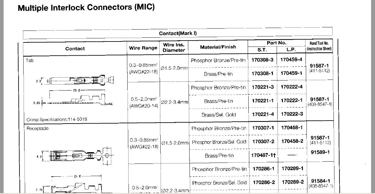
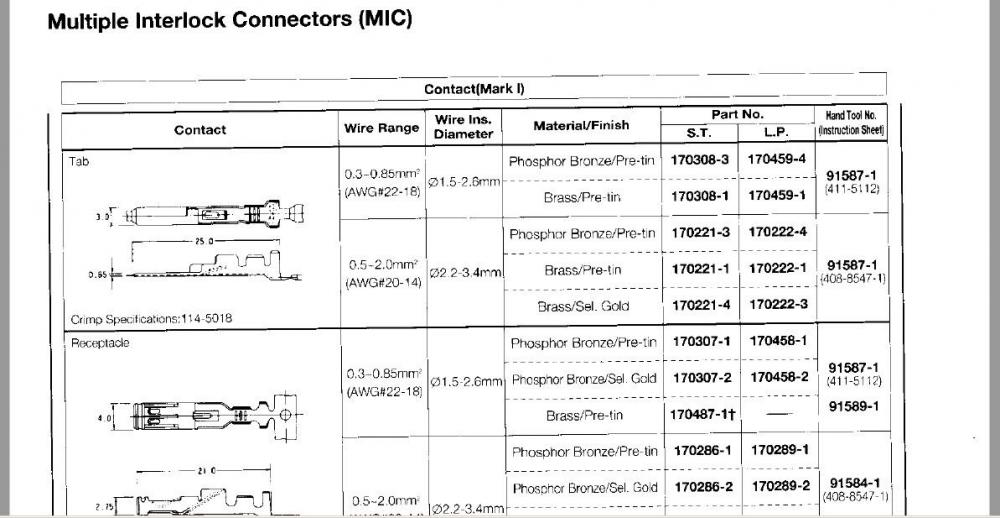
Yeah, those part numbers look promising. Seems maybe I didn't look hard enough? Haha! According to the documentation I have, the 170221-1 is a Mark-1 male tab... Tin plated brass, 20-14 ga wires. And the 170286-1 is a female socket... Tin plated phosphor bronze for the same wire gauges 20-14. The connector housing part numbers you posted didn't show up in the little amount of documentation I have, but they are close to other numbers that did show up. Meaning they probably are Mark-1 and just have different cavity numbers or something. For example, 172024-1 did show up as an 11 position housing. So keep us posted when the parts get there. I'll dig out my Mark-2 parts when I get the chance and see what part numbers I ordered. Not that it really matters, but.....
-
If I can figure out where my notes are, I'll let you know what MIC contacts I already bought. You know.... Some of the wrong ones.
-
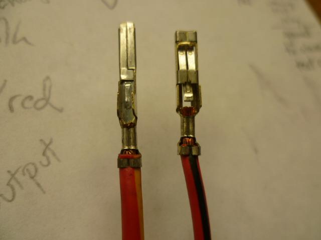
Well you really need to figure out if it's Mark-1 or Mark-2 you're buying because the Mk-2 stuff will not fit into the Mk-1 shells. Been there, tried that. Doesn't work and I can send you some if you want to see them. I dug around a while ago and couldn't find any Mk-1 stuff*. And in a feat of desperation, I did buy some of the Mk-2 stuff just to see what would happen. As I remember, there was no Mk-1 stuff at DIgikey, but I may have turned up something at Newark or Onlinecomponents. And... If you DO manage to find some Mk-1 contacts, buy some for me too, OK? It sounds like you are trying to do some of the same headlight stuff I did a couple years ago. In the end, I bought a whole engine bay harness and stripped out the wires (with connectors already attached) from that one. It had previously been hacked up some by a PO so I considered it a cadaver and didn't feel too bad about completely stripping it down. * At least in small quantities... I think I remember finding some of the contacts in full rolls, but couldn't justify the cost of buying the whole thing.
-
Everyone likes pictures, And an example snippet from one AMP's catalogs:
-
AMP - MIC Multiple interlock Connectors MK-1 The mark 2 (MK-2) stuff is easy to find but it won't work. The older MK-1 (Mark-1) is difficult. I'll take a look through my notes, but I don't think I turned up a viable source for small quantities of those.
-
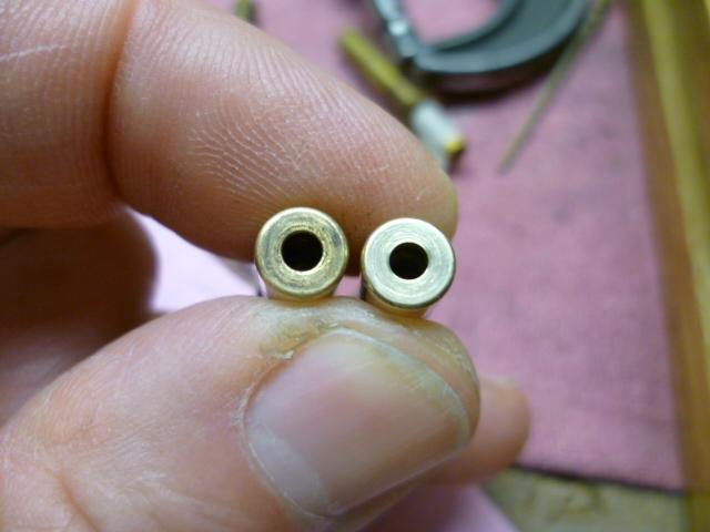
Yeah, it sounds like you're definitely in the market for a new pair of needles, and maybe a pair of nozzles as well. Material removed by corrosion will wreak havoc on your idle mixture. And if there's pitting on the needle, it's certainly possible there's the same kind of corrosion on the nozzle. That may explain why the needles fixed one carb, but not the other. As an example... Here's a pair of nozzles. One enlarged by corrosion and another with an accurate original sized hole. The corrosion ate away so much of the material that I can see the difference with the naked eye. At idle, it takes a very small gap to make a huge difference. So...... Weren't your carbs rebuilt? Sold to you in good working order? Slap-em on and go? Might there be some negotiation and relief there? And as for swapping and mixing and matching parts between carbs... I think it's OK as a test (like you've done), but I would want to keep the original pistons and chambers together with the carb body they came from. You could possibly move the pair (both piston and chamber) over to a different carb body, but you would have to re-align the nozzle. I wouldn't trust that it would line up after moving to a different body. But the best thing would be to just keep them together on the same body. I should go into the carb rebuild business.
-
What is the history of the nozzles? And who did the alignment of the nozzles after the rebuild process? Is that something you did, or did they come to you already aligned?
-
Swapping in a pair of known stock needles would be a good test, and something relatively easy to try. I know you said you are already positive that your float levels are on target and your chokes are not sticking down at all. And with those two things not causing a problem, I'm having a hard time coming up with a scenario that would result in running rich without some sort of damage to a nozzle or a needle or a wrong part installed. Like I said, lean is easy. Rich is more difficult assuming you have already ruled out the easy ways to run rich (float levels and sticky chokes).
-
I agree with the above about the paint. If that's original paint, I'd try hard to preserve it. I also agree about the tranny... Swap it for a manual, but keep all the old parts. So I'm surprised it didn't go higher as well. I'm thinking the high prices for Z's hasn't gotten to the 280's yet. And lucky for you! Beautiful car and you stole it!
-
The factory standard needles are N-27, but a lot of people install SM's instead. That decision works out well for some people and some others report running rich. The number is either stamped or inked onto the hilt and is only able to be seen with the needle removed from the suction piston. However, if they are inked (and not stamped), the ink printing is pretty fragile and is often destroyed with handling or chemicals. In other words... It would not be unusual for you to pull the needles and find only remnants of the number stamp and not be able to tell what they are from the ink printed mark. It's easy to make the carbs run lean, but it's usually a little more difficult to make them run rich*. To run rich, it takes deformation of a needle or a nozzle, or the installation of incompatible parts. Did you ever get in touch with Paltech and ask what needles he used? * Assuming, of course that the float levels are OK and the nozzles are not sticking down with the choke.
-
-
Actually, it was more like this: https://youtu.be/YdElbI77IfY?t=32 Haha!!