


Captain Obvious
Community Member
-
Joined
-
Last visited
Everything posted by Captain Obvious
-
Well it's going to take the rest of today to get THAT out of my head. Hold on.... Some old Aerosmith ought to do it... Although I did like the S.S. Sensible. Haha!!
-
Is there any way to be sure that it left the factory as a Black Pearl? Some sort of special stamping somewhere or something?
-
Nice overview on the experience history. I'm no mechanic either, but like you, I have found that attention to detail and cleanliness can go a long way towards success. And I'm glad to help. That beer will happen someday!
-
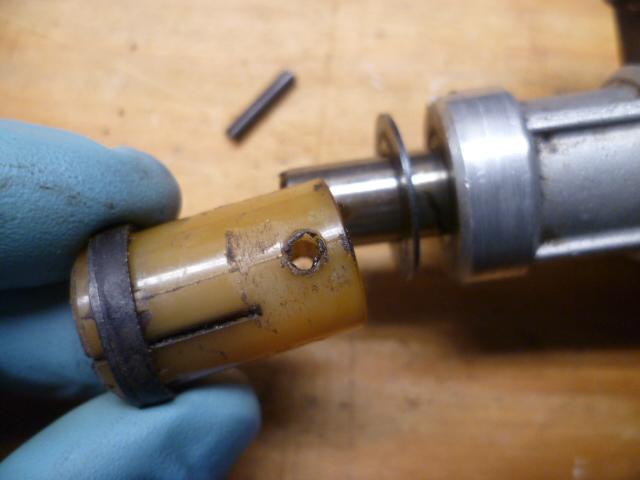
That part affects is the axial end play of the distributor shaft in the housing. If you switch over to a different piece (whether that is plastic or metal), you should check the end play and adjust the gap filling washers accordingly if necessary.
-
Yeah, the timing kits seem to be all over the place, but regardless of which one people use, there doesn't seem to be a lot of chatter about failures due to cheap or inferior versions. In other words... The timing kits all seem to be acceptable. That said, there are two things that I would really try to avoid. 1) Master links, and 2) cam gears without timing marks. I'd really prefer a continuous chain. What brand is that? As for the bright links, you can just do what you did and it's fine. Those timing links line up every 22 rotations of the crank (11 rotations of the cam), so you really only need them once: https://www.classiczcars.com/forums/topic/62752-bright-links-on-timing-chain-line-up-every-11-rotations/ The timing gashes on the back of the cam gear are more of a nuisance. If everything you're putting in is new, you can/could/should be able to assume that there is no stretch and the timing is fine on hole #1, but it would be nice to have those marks. That's the Cloyes aftermarket cam gear, right? So how new are you to this hobby? You seem to be doing pretty good for someone new?
-
Yup. You still got it. And you're clearly a more comfortable man.
-
Yeah, I didn't even mention inspecting the threads on the head. So between sketchy heli-coils which probably led to uneven pressure, and the burrs on the rear journal, it's no surprise you had issues with alignment. Aren't PO's wonderful? So I bet you feel pretty good about it now that you have that cam spinning free, don't you? It's great when you find the real underlying issue(s) and fix it! Awesome!
-
LOL. Every pose anyone ever did is on the internets somewhere. But don't forget... Use the approved poses if you want to be a meme'r... Peace sign, bunny ears, fake wiener.
-
I have heard it said that "The original gasket (for the ZX) was made by NRZ Nippon Reinz". However, at some point Nissan changed sources because the last one I bought (from Nissan about a year ago) was made by Stone.
-
Excellent. And then not so excellent. I guess I'm a little relieved that sort of stuff doesn't happen to just me! So I'm unclear on the assembly lube you forgot. You don't need it between the towers and the head... You only need the assembly lube on the cam journals where they ride in the bearings. And you don't need to dismount the towers to put that lube on.
-
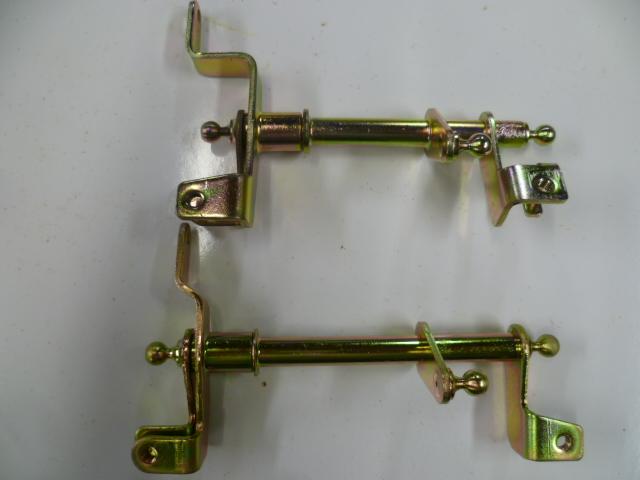
On that rearmost tower, I've seen situations where the cam journal was slightly narrower than the bearing in the tower. And that can result in a small lip in the tower bearing surface at the rear edge of the rearmost tower. Since the front/rear positioning of the entire cam is controlled by the hardware at the front of the cam, it's possible to insert the cam "too far" into the journals when doing a test fit. And if you do that, you can push the cam into and over that lip on the rearmost journal resulting in it being difficult to spin. I don't know if all of the heads work out this way, but in my limited experience I've seen that. So, the question is... Does the cam slip into the rear most journal almost all the way before it gets harder to turn? Or does the difficulty in turning it start as soon as you start to get that rearmost bearing engaged?For me, that Memphis ZCON was the start of faces to a screen, but it has continued since then. I've hopped into a car with a Z guy I had never met before... In the middle of traffic. And after verifying that neither of us was carrying and axe, we went on a pub crawl. I've met for pancakes in Princeton with Z people I had never met before. I've met for project show-and-tell and food north of Toronto with Z people I had never met before. In Orlando, when you've seen enough of the Great Mouse and the other tourist attractions... I've met up with Z people there. I've even been invited to a meal at the parent's house of a Z guy who used to live close to me but now lives completely at the other end of the country. When traveling on completely non-Z related events, I've made stop-offs to see some friends and make new ones. I've met for coffee (and hopefully provide a short respite from the rigors and boredom of work travel) with Z people who find themselves in the area for a layover. I'm wondering if it's just the food and drink.....Right. I should have mentioned that. But once they have seated, things should, or at least "COULD" be good. And something else I didn't mention... When you're tightening the bolts. the torque should shoot up real quick like. You shouldn't need to use the bolts to jack the towers down onto the head. It should go from nearly zero torque to turn the bolt head to significant torque in a very small amount of rotation. That's the sign that you had every thing clean, had no burrs, have the towers aligned on the dowels and seated properly with the plastic mallet tapping. if you find that you have to use a wrench and turn the bolt a significant amount* before the torque shoots up, you should stop... Take it apart again and find out why. * More than a half turn maybe?And one more pic just to round out the collection... I'm always mentioning that the center linkage for the round-tops is longer than the linkage for the flat tops. Here's the two side-by-side so you can see the difference(s). I tried to line up the right ends for the pic:
 And just so the flat-top guys don't feel out in the cold... Here's a pair of linkages for between the two flat-top carbs. Same scenario as above. One has had the throttle opener arm removed, but the washer is still present: It looks like it was done with a hacksaw or cutting disk. Again, I (probably) did this some time ago, but don't remember the details. Whoever did it was clever enough to place the saw slit on the underside where it wouldn't be noticeable when installed. I like to think I'm that clever. Here's a pic:
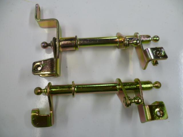
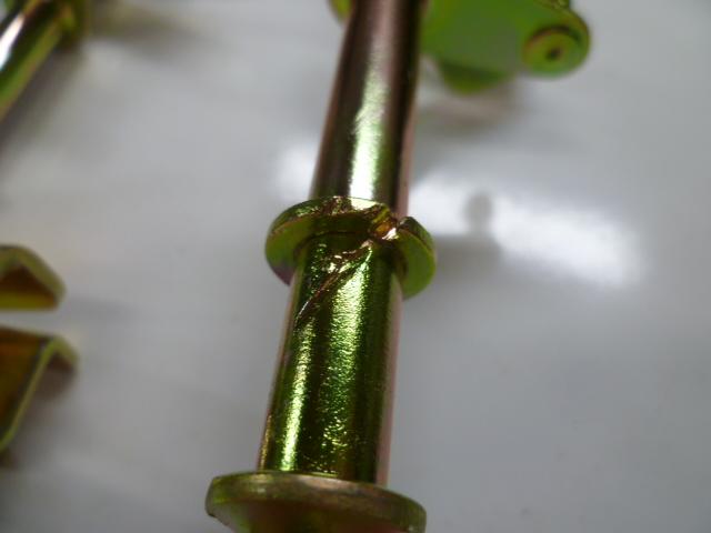 I took some pics. Here's are a pair of linkages for between the two round-top carbs. (Obviously) the top one has the throttle opener pivot, and the bottom one has had it removed: Shot from the end showing the throttle opener arm: And here you can see the file marks from where the pivot was removed from the other linkage. I (think I) did this, but it's been so long that the details have faded. In any event, here's the linkage with the pivot and brazed washer mechanically removed:

 First thing I would do is make sure the mating surfaces (bottoms of the towers and mounting pads on the head) are clean enough to eat off. And I would (under magnification) make sure there were no burrs or "upset" metal anywhere on any of the mating surfaces. One might wonder how burrs might get kicked up? Well in the case of the head on my car, my PO used a screwdriver between the towers and the head to pry some of the more stubborn the caps off. That screwdriver wedging caused burrs that prevented the towers from sitting properly after that. So if you (or a PO) did anything like that, you need to look into it. As for the percussive finesse... I would put all the caps in place, lightly tap them with a plastic mallet to seat them, put the bolts in and snug them up to a low torque. Maybe a third of the final torque. Then put the (well oiled) cam in place and see how it spins. If it spins free, then tighten up the towers to 2/3 spec and see how it spins. If it still spins free, tighten the towers to spec and see how it spins. If it still spins free at full torque, congrats... You're done. Let's start there and see what happens. If it DOESN"T spin free, then you need to start the percussive adjustments. But I'm going to start off hopeful and see what happens?Cool. So are you going to drive around for a while with that attached? I still haven't looked closely at the wiring diagram to see how things are really connected. I will do that when I get a chance.What he said. I went to ZCON Memphis as well, and during that trip a whole bunch of us jelled into a collection of good friends. More than just a bunch of people who owned similar cars, but people who honestly like each other and like spending time together. I really hope I have a vaccine in time to go to ZCON later this year. I've got people I want to see. And the cars are nice too.I think you should google that. "Hummer" "Forum"CanTechZ, The linkage between the two carbs on your Canadian car looks the same as the one they used for Europe. And as mentioned above, the US version is different. Not without a torch. The linkage is brazed together. Best bet (and something I have done in the past) is to remove it mechanically with saws and files. And speaking of such things... @Dadsun , I wish I had known you weren't going to run the throttle opener when I sent those other parts. I think I've got said 240 linkage piece here with that part of the linkage removed. I'll see if I can find it and snap a pic.Interesting. I don't think we ever got that damper device in the US. We got the throttle opener system instead. And the linkages are clearly different between the two systems. I wonder which worked better.Haha!! Actually it was an accidental hit. I was joking that maybe you were printing something more green. On your printing press in the basement.Excellent. I noticed pretty much the same thing. Except in my case, after I replaced my wheel bearings, I could hear the diff whine.


Important Information
By using this site, you agree to our Privacy Policy and Guidelines. We have placed cookies on your device to help make this website better. You can adjust your cookie settings, otherwise we'll assume you're okay to continue.