


Captain Obvious
Community Member
-
Joined
-
Last visited
Everything posted by Captain Obvious
-
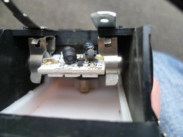
The key ZH is talking about is the same thing I was talking about earlier... "Be very careful of the position of the keyway that drives the harmonic balancer. Make sure it's correctly sitting in it's groove before you push the pulley (balancer) into place. If you don't you could crack the balancer when you tighten the big bolt in the front." That key fits into a semi-circular groove cut into the snout of the crankshaft. The problem is that since the key is semi-circular, it can "rock" in the groove. And if that happens without you realizing it, you may think you have the pulley fully seated onto the oil slinger, but you don't. Then when you put in the big bolt in the front and torque the crap out of it, you crush the key, mangle the oil slinger, and worst of all, crack the pulley casting. It's not pretty. So you have to make sure the key is properly located in the groove before you put the pulley on. And I would recommend you use a bright light and look down the pulley groove to make sure you see the key in there looking like it should before you put the big snout bolt in.
-
Yeah, that looks good. I would probably stop there. So this peroxide and UV combination thing... Is this internets science? Most times UV makes plastic worse, not better. Not arguing with the results, but wondering if the UV was really adding any value?
-
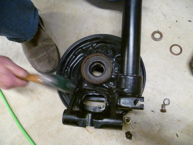
Yes, the seal on @Av8fergs pic looks good. Too bad the timing cover is so shiny.
-
Haha! I got two parts to the answer to that... First is that the pics of that backing plate work was a special situation where I had other people over for a "rear bearing party". I was doing mostly directing and telling other people what to do (clearly, as it should be). On that day, I got to hold the camera and take pics of other people doing real work. That's not me swinging the hammer, it's one of the other attendees. The second part to the answer is "I've found it worth the effort to try to make it happen." By that, I mean... I do so many car projects (that I have to refer to again sometime in the future) that I really now try to take pics along the way. Still, there are plenty of projects that, just like Jeff, I'm in hurry-up mode and can't deal with the camera at the time. And as Murphy dictates, those hurry-up jobs are invariably some of the ones I WISH I had pics of at some point later.
-
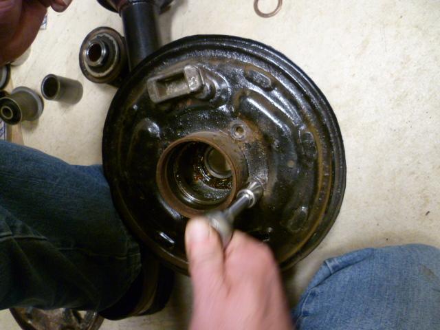
They are not one piece. They just need a little persuasion. Take the bolts out: Turn it over and give it a judicious whack. Don't go postal on it, but some BFH persuasion might be necessary. And here's a shot with the plate removed:
-
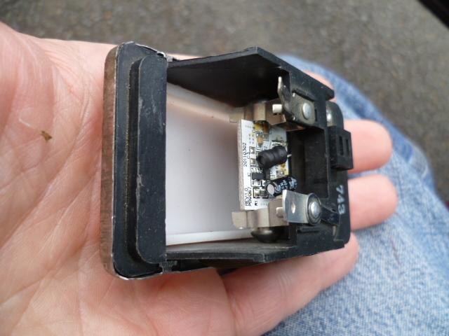
The newer ignition switches had a little set of contacts inside that would activate a beeper if you left the ignition key in the slot. They called it an "anti-theft" feature and I'm assuming that it was a reminder to not leave the keys in the ignition switch when you left the car (like anyone does that anymore...). The earlier cars did not have that feature and the little beeper switch was not present inside the ignition switch. So I don't know what year you're working on, but the wires in question are related to that feature.
-
I sent out a batch of parts to be plated late last year. As part of the prep of those parts, I did a citric acid soak to dissolve (chelate) rust and strip off the original chromate and zinc. Some of the parts I soaked (like throttle linkage and ash-tray slidey bracket) had plastic bits on them that had yellowed. After the citric acid soak, they looked great. So if your peroxide doesn't do what you wanted, you might want to try citric acid. Do be aware, however, that the citric acid will eat the yellow chromate and zinc plate off the metal stuff (which is why I was using it). But the point is, if you want to preserve the original zinc/yellow, you can't do the citric.
-
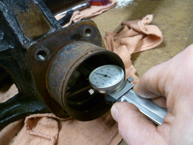
Yeah, sorry to be the bearer of bad news, but there's no way that bent one would ever seal. It's important to get the seal pressed evenly and squarely all the way around. If you don't have a press (that can help assure squareness during assembly) and you're doing it by hand/eye, you need to make sure you don't get it cokked on an angle while you're pushing it in. Those seals have a thin metal reinforcing structure molded inside the rubber. If you bend that internal structure, you're screwed.
-
No, that does not look OK. Not only is it pressed in too far, but the seal is damaged. Bent and creased on the left side in the pic. You cannot use this seal anymore. If you haven't already, you need to pull that one out and throw it out and start over. Sorry. And also... Be very careful of the position of the keyway that drives the harmonic balancer. Make sure it's correctly sitting in it's groove before you push the pulley (balancer) into place. If you don't you could crack the balancer when you tighten the big bolt in the front.
-
Pot... Meet kettle. Kettle... Meet pot.
-
I dug out my order info for the map light. I got that map light from superbright as well. The part I ordered (five years ago) was WLED-WWHP15-TAC But it appears they have changed the numbers and that part is now listed as 921-WWHP15-TAC https://www.superbrightleds.com/moreinfo/miniature-and-subminiature-bulbs/921-led-landscape-light-bulb-15-smd-led-tower-miniature-wedge-retrofit-100-lumens/2508/ There are different tabs for the different "colors" I like warm white (because I'm old).
-
Yes, it's warm white, and I love it. As for a P/N, give me a little bit and let me see what I can dig up...
-
Haha!!! Next time we're together, remind me about taking a wing man on potentially risky excursions. And how not all people are cut out for the job!
-
Yeah, that's what I was looking for. Something easy. I know you don't have a lot of time and are just looking for a patch at this point. So if that works for you, just tell the hauler guys to turn the key to ON and wait five or ten seconds before cranking the car. You could even tape a sign to the steering wheel if you need to. Haha!
-
LOL. Just stay safe!!
-
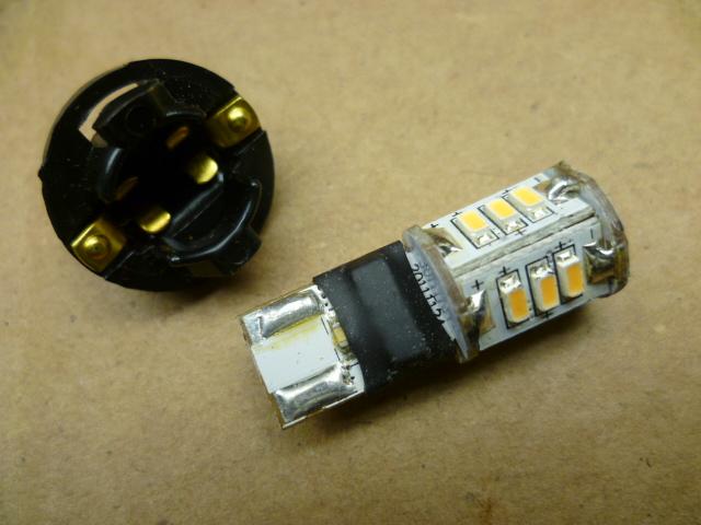
I did the map light as well. I think I posted some details about that somewhere... But if I did, the pics are probably dead on that too. Here's what I used and I think it's fantastic! I'm not sure all years used the wedge base though.
-
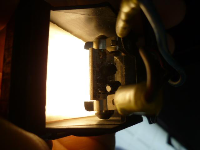
Yeah, it was a little bit of work to get the larger 6-LED bulb in there, but I really like the way it turned out. Great brightness, and warm white, so no blueish harsh stuff going on. If you didn't know better, you would assume it's an incandescent. As for the old dead photobucket sucks pics... I think I can post them here. Here's some pics showing what I had to do to the mounting clips to get the bulb to fit. I used a carbide burr on a dremel. Don't get tiny brass slivers stuck in your fingers (or eyes): And even though you can't tell much because there's nothing else to compare it to, here's the obligatory "ON" pic: And again, if you don't want to deal with grinding off a little of the brass fingers to fit the 6 LED festoon in there, you can get a 4 emitter version instead. And since they keep making LEDs brighter and brighter, I wouldn't be surprised to learn that todays 4 LED bulbs are as bright as the 6 LED bulbs from 7 years ago when I did this mod.
-
Another simpler option would be to simply disconnect the oil pressure sender connector and let it hang. The fuel pump will run any time the key is ON.. Of course, the oil pressure gauge won't work with that connector off, but for the trip to AZ, it would be OK.
-
Oh, and I took a quick look at the wiring diagram for the 78. There are two relays up in the engine compartment that deal with the fuel pump. The "fuel pump control relay" (which has five wires) and the "fuel pump relay" which has four. If you pull the connector completely off the relay with five wires, there should be two W/B wires leading into the connector. Short those two W/B wires together and it disables the interlocking. The fuel pump should run any time the key is in the ON position. Let it hanging off the relay with just those two wires shorted together and put some tape on it? As a quick alternative, that might get you through the time crunch? However, I just took a quick look... If you're going to do this mod, let me know beforehand and I'll look into it a little more thoroughly.
-
Yes, when the check valve is working, then everything after the pump stays full of fuel and pressurized. Supply line from pump the engine bay, filter, rail, injectors... Everything between the pump and the pressure regulator. And yes, if you put the check valve up in the engine compartment, then you will not have pressure in the line between the pump and the engine bay, but everything else should be pressurized. I'm not sure the problem is the pump losing prime. I've found that if you disconnect the supply line to the pump, fuel comes out. Implication being that the pump is gravity primed. I'm thinking that maybe the fuel is "siphoning" out of the rail somehow to achieve an equilibrium point where everything is even. That point may not be as low as the pump, but it might be lower than the rail. If that's the case, you would have to run the pump to refill the rail, but the pump itself has not lost prime. In other words, I'm thinking that the check valve does two things: 1) It keeps everything pressurized 2) It prevents "backflow" through the system that would allow the rail to drain from gravity? Just a theory.
-
The original check valve is screwed into the outlet side of the pump. So in "circuit" it's installed between the pump and the rail, not between the tank and the pump. That said, for a quick fix, I think you could put something right before or after the filter. Putting something up in the engine compartment would certainly be faster and easier than dealing with anything underneath the car back by the tank. Another option might be to do a (simple?) wiring modification so that the fuel pump is always running with the key in the ON position? Wouldn't have the safety feature of shutting off the pump in the event of a collision, but you would just hope the movers don't get involved in a big pileup with the car loading it onto the trailer. I'm thinking that would allow the fuel pump to prime like the newer cars do. Just tell the movers to turn the key to ON and count to five before trying to start the engine?
-
IMHO, there's no need for the switch to be a waterproof type. If you're limiting your search to switches that are sealed, you might get more results if you are willing to accept something that is not weathertight.
-
I put O-rings on the shafts. I'm sure it's not as good as installing completely new unworn shafts, but it's something I can do here with the machines I have.
-
Couple of questions/comments... In your box of things to be plated I see a piece of throttle linkage with the plastic ends. Some people send those out for plating and they turn out fine. My experience was not so great. Not sure if my guy used stronger acid or a longer soak time, but the plastic shows some damage from the process. Still usable, but damaged. Also if you are going to send the linkage bits, I would take the adjustable end and lock nut off first. My thought is that you don't want to end up in a situation where future adjustment exposes a part of the linkage that did not get fresh plating. Lastly, I see the outer ring from the master cylinder cap. Are you planning to send the other portion with the rubber seal on it? Is that in there somewhere?
-
I've been wondering about the changes made to the round tops through the years as well. I mean, I know that the four screws were used from the start through the 71 model year, and then they switched to the 3-screw version for 72, but that's about all I know. There seems to be differences in the 4-screw versions used over the years (as described on the Z-therapy spotter's guide), but the pics are so small and the details so vague that I'm looking for something clearer. Do we have any experts on the finer points of the different versions used over the years? There was some stuff mentioned in that thread about the supposedly 31K mile car on BAT (the one that had the 3-screw carbs on it when it should have had 4-scew). They talked about tabs on the linkage ears and rear pointing vacuum ports... Anyone know the details? Tab width (seems all the 4-screws are narrow) Float chamber lid shape and mounting screw tabs Steel or plastic dashpot knobs Vacuum tab location on balance tube Hook or no hook on the linkage between the two carbs Linkage ears (is this the same as the hook?) Here's the post from the 31K BAT car: https://www.classiczcars.com/forums/topic/64539-31k-miles-series-i-240z-up-for-auction-on-bat-over-100k-on-first-day/?page=3&tab=comments#comment-608149


