


Captain Obvious
Community Member
-
Joined
-
Last visited
Everything posted by Captain Obvious
-
Have you put a vacuum gauge on the balance tube to see how the vacuum looks? I'd try it at both your more centralized PCV connection, and also at your brake booster connection on the end. Just to see if you can glean any useful info from the gauge?
-
Or maybe.....

-
Oh, and what caught my eye first was the mention that it was "For a ’72 240Z". Like the year matters for what film would work. So by saying it out loud, I guess I'm risking making the bots better, but that's what really started me wondering.
-
Well honestly, those were my words. I was trying to highlight the fact that it looked fishy (to me) that someone would go through the time and effort to create a brand new account... Just to say that useless thing. 🙂
-
@Mike
-
I believe that piece of plastic is known as a "strain relief". The purpose is to help prevent damage to the softer delicate fusible link wire when you are pulling on the harness. In other words, if you pull on the wiring, that plastic strip is supposed to protect the link wire. But yours, like so many others is broken and not doing anything.
-
That method will not work for the Z because the Z ignition lock uses a solid pin for retention, not a roll pin. I mean, I guess you could drill directly into the pin and then thread it and use a puller to yank it, but the geometry is all just so small. Last time I removed a pin, I drilled into side of the lock cylinder (figuring that I didn't care if there was a hole in it since I was replacing it anyway). Something like this:


-
Hahaha!! We all have our strengths. 😀
-
You get the picture. https://www.youtube.com/watch?v=-9NMt42il4Q
-
Sorry, I'm further out on my limb than I should be. I said "from what I've seen", but in reality, I should have said something like "I've not had direct experience with the new OEM knobs, but as discussed here on the forum...." So let me try again with that in mind. I've not had direct experience with the new OEM knobs, but as discussed here on the forum, Nissan changed the size of the shift knobs somewhere along the years. The knobs originally supplied on the Zs are smaller than what was supplied as a replacement some years later. As for the timing, the first time I saw mention (with supporting pics) of this situation was in 2006. Posted by Arne: https://www.classiczcars.com/forums/topic/20489-restoring-origional-shift-knob/page/2/#findComment-189573 There was also a second confirmation about the size change where GongZ bought a new "Genuine Nissan" and the set out to maybe modify it to the original smaller dimensions: https://www.classiczcars.com/forums/topic/44587-5-speed-knob-reproduction/page/7/#findComment-408076
-
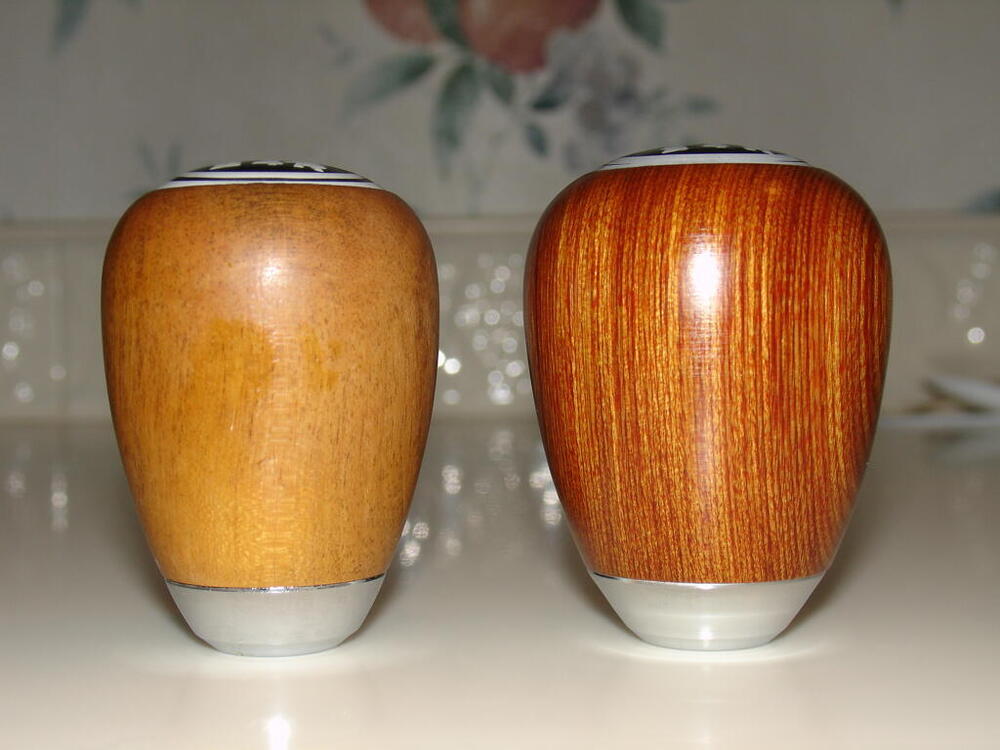
Yes, from what I've seen, Nissan changed the size of the shift knobs somewhere along the years. The knobs originally supplied on the Zs are smaller than what was supplied as a replacement some years later. Here's a pic showing an older original Z car shift knob and a genuine OEM replacement that could be purchased some years later. Both are genuine OEM, but the newer version is larger than the older original. Original 240 knob on left, newer Nissan replacement on right: So yes... For your car, NOS isn't good enough. You want an "ONOS" (Old New Old Stock). 🙂 I thought I had pics of the ONOS knobs I have here, but I can't put my finger on them. I'll have to take some fresh pics when I get the chance.
-
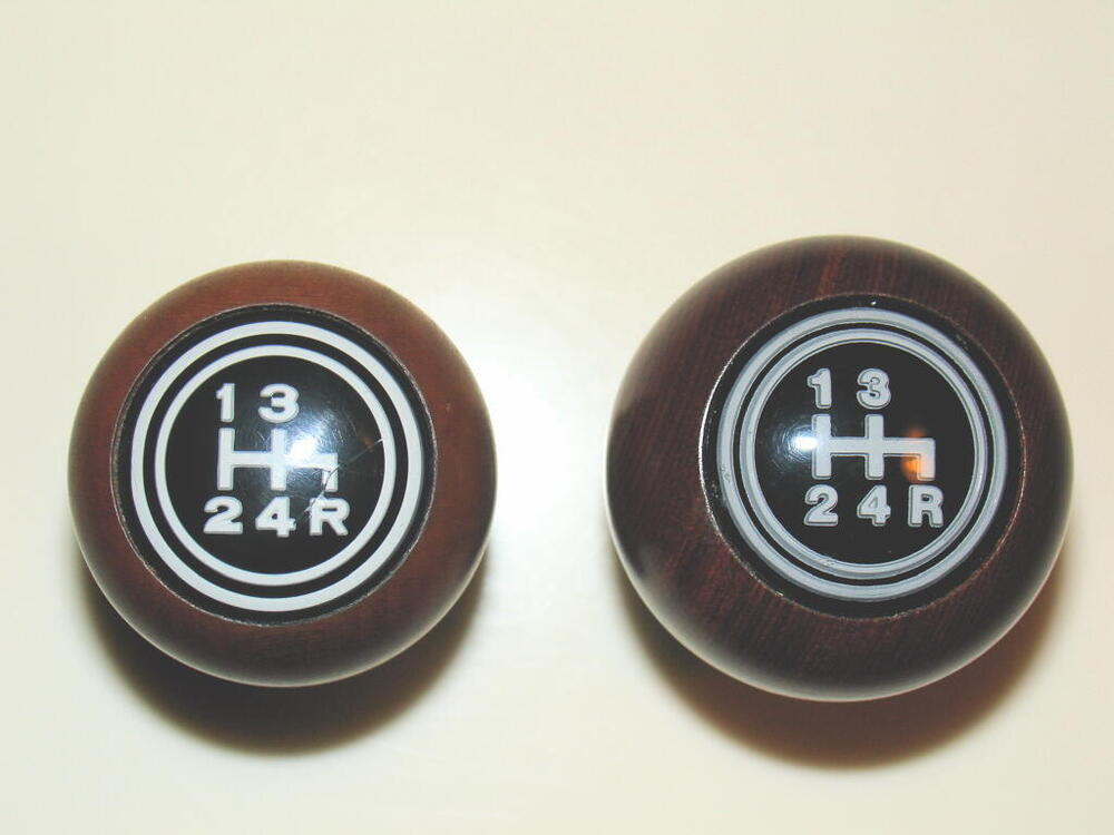
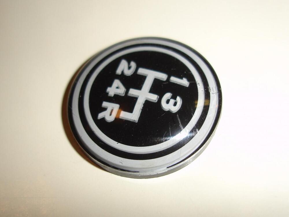
Beautiful car. I'm certainly no expert, but I think I see a couple minor things that are not quite correct. For example, I don't think the shift pattern emblem on the shift knob is quite right. It looks like a flat bottom (presumably second surface screen printed) emblem instead of the reverse embossed that was originally used. I don't see the "depth" that should exist on the shift map: This pic shows the 3-D "depth" of the original map: And (hopefully not being too self-serving), I've got a beautiful NOS shift knob on the shelf here if you're interested. Haha!!
-
@Yarb https://youtu.be/Or4Fq31kl3Q?list=RDOr4Fq31kl3Q
-
Spot The Bot!! Wonder what it is about this thread that is attracting the bots...
-
Excellent. Glad you got it working!
-
-
Can you post a video of this test? And can you make sure it's possible to see the state of the front turn signals as well? Don't need a mirror or anything that complicated... Just make it such you can see the glow or reflection from the fronts so we can see what they are doing at the same time? Your description of the results didn't make sense. Probably just a simple typo, but it would be best to just post another quick clip. You mentioned right side twice?
-
Weird. It should not be doing that. So the first thing that catches my eye is... When the hazard flasher is in it's OFF state, neither side should be lit. At all. And when the hazard flasher is in it's ON state, both sides should START their sequential slide across the bulb face. Yours get completely out of sequence and sometimes your left side even remains lit when the hazard flasher is in it's OFF state. That should never happen. The sequential feature requires the running of a new power wire (pink) to the rear of the car, but that wire is not necessary if you are running the lights in standard mode (not sequential). My spidey sense is telling me to check the integrity of that wire. Can you program your assemblies to function in standard non-sequential mode and see what happens? Next, can you put just the left side in standard mode and see what happens? (Left side in standard non-sequential and right side in sequential mode 3 - in to out and back) Also, what year are you working with? I'll look at the wiring diagrams.
-
Well without being there and looking things over in person, I can only theorize. And the theory is that the rear circuit WOULD work if you could get enough pedal travel to actually build pressure. But all the other forces at work (having to fully compress the front circuit spring, having to shuttle the brake warning switch piston, having to move the guts of the proportioning valve, having to take up the play in the rear wheel cylinders before the shoes contact the drums......... all that) are making it such that you just don't have enough pedal travel available to build pressure before the pedal hits the floor. That's why I was suggesting that a couple rapid pumps might get the rears to work enough to stop the car. My suggestion at this point would be to tell the mechanic to fix the front circuit... Make a new hard line, bleed the master, bleed the fronts thoroughly, bleed the backs thoroughly, make sure there are no leaks anywhere, and then see how the brakes feel. If they feel good, you're done. If they still don't work, then lets go from there.
-
So... You're asking "Why does the description of how it is SUPPOSED to work differ from the way it ACTUALLY works?" I'm not sure. I'm thinking you'd need to check with the guys who designed the thing. 🙂
-
With oil in the dampers, it is supposed to be difficult and slow to lift the pistons. So for proper operation, BOTH of them should have heavy resistance when you try to lift them. Sounds like you have a problem, but that problem is with the one that's easy to lift. The one that's hard to lift is the one that's working correctly.
-
When one circuit in the master is empty (doesn't matter which, front or rear), the master cylinder travel will be very large compared to normal. That's because you have to completely compress the spring in the dead circuit before the system builds any significant pressure. Normally, neither spring inside the master is compressed much because both chambers in the master are full of fluid (which is not compressible). But with an empty circuit, that is not the case. One circuit has to compress completely before the other one does much of anything. So.... What does that mean to you? It means that when you push the pedal, nothing happens until you get waaaaaay down to the floor. And even then, you also have to shuffle the little warning switch plunger and the proportioning valve movable bits. Both of those things take up some fluid volume, and In the end, you might not have enough pedal travel to ever build enough pressure to get a firm pedal, even near the floor. Sometimes a couple quick pumps of the pedal will help because the drain back valves built into the master may slow the flow back to the reservoirs enough to build some master pressure. Bottom line, I think your proportioning valve is fine. I think this is all related to your empty front circuit.
-
Most of the sway bar links I've messed with include a feature that limits the amount of tightening travel long before the bushings get all squished out like that. In other words... The nut usually bottoms out on the threads when the proper amount of bushing squish has been achieved. It looks like the links you are working with have way more threaded length than necessary.
-
Spot The Bot - The Sequel!!
-
Spot The Bot!!!


