Namerow
Community Member
-
Joined
-
Last visited
Everything posted by Namerow
-
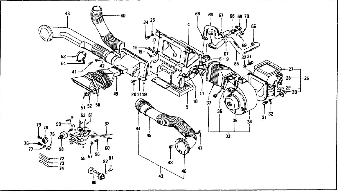
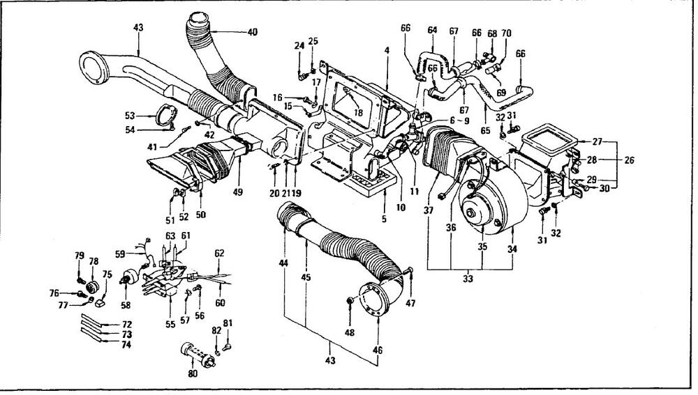
Item 50 in the FSM illustration (exhausts through the rotating chrome grille, Item 80). Cutting and then gluing the foam pieces around the duct's inside surfaces is finicky work. I can only assume that Nissan decided the benefit outweighed the additional manufacturing cost. You need to use open-cell foam for this location.
-
Maybe too late now, but I posted printable templates for all of the heater boxes, flaps and ducts in 'Resources - Knowledge Base'. Might save you some time. Don't overlook the foam liner for the centre air outlet duct. It's there to reduce air rush noise. Also: Be careful with the edges of the vinyl-faced flap coverings. They may need some edge profiling or cutting back to keep them from snagging as the flap moves from 'open' to 'closed' position. You don't want those things coming loose after you've installed everything back under the dash.
-
I don't recall seeing any restoration write-ups that have been specific to the centre console. I think you'll find (limited) discussions on the topic as part of broader write-ups on Interior restoration. If memory serves, the full-restoration thread done by CSCZ member @wheee! was based on a 280Z, so you might find some tips there. Most of the coverage that I remember deals with repairing the consoles for earlier 240Z models, which were prone to cracking where the choke lever assembly attaches. Perhaps it would help if you provide some details about the condition of your console, which will help us to understand why you think you need to replace some of the hardware. As for the removal/reinstallation process, the Factory Service Manual (downloadable for free from the 'Resources' section) should be your first pint of reference. SEM 'Landau Black' paint is generally considered the go-to paint for reconditioning the Z console. Most members use a 'chrome' pencil to restore the trim highlighting. Cracks can be repaired with cautious use of the ABS plastic cement used for plumbing. If its a long crack, you should probably reinforce the back side with a secondary layer (an old credit card or hotel key card works well for this purpose).
-
Agreed. @cgsheen1 Would you mind spending a couple of extra minutes to post your write-up in the CZCC 'Knowledge Base'?
-
Well, the good news -- maybe -- is that Pilkington (Britain-based, with manufacturing operations in several countries worldwide) has been owned by Nippon Sheet Glass in 2006 and now operates as a NSG subsidiary. Pilkington's website describes their automotive business as follows: " Operating as a single global organization serving the Original Equipment (OE) and Local Automotive Glass Replacement (AGR) Aftermarket sectors... The North American aftermarket operations supply laminated and tempered glass for the automotive glass replacement market. All products meet or exceed Federal Motor Vehicle Safety Standards. Products are shipped from its distribution centers in Columbus, Ohio and Phoenix, Arizona to external retailers and wholesale customers and its network of company-owned wholesale service centers throughout the US... Windshields, sidelites, backlites, accessories and specialty AGR products are included in the customer offering of Pilkington North America AGR". The British Pilkington website includes 'Pilkington Classics' products and lists hundreds of replacement items for older cars. That list includes both a 240Z windshield and backlight. It looks like they operate on a custom-order basis and no prices are shown. I suspect they wouldn't be interested in filling single-unit orders, but would be amenable to an order for 20+ from someone like MSA.
-
I believe that the 'XXX"' moniker is Pilkington's short-form for their 'Triplex' line of laminated automotive safety glass. Pilkington has been manufacturing automotive glass products at a plant in Collingwood, Ontario since 1973. Hard to believe that they'd be engaged in short production runs of replacement glass for vintage cars, but you never know. A brief write-up that I found for Pilkington North America says, "Its sales are made up of 70 percent automotive products (57 percent Original Equipment and 43 percent Automotive Glass Replacement) and 30 percent architectural". It would be interesting to know how long ago your MSA-sourced windshield was actually made.
-
Some suggestions for new gaskets: - thin (1/32") , closed-cell neoprene sheet (Michael's craft store) - the material used in those stretchy exercise bands (Canadian Tire - sporting goods section) - lid from a margarine tub (soft polyethylene) I really don't think there'll be an issue with vibration damping, but at least it'll be easy to go back to paper if there is. If you want to try sealant instead, how about strippable window sealant (DAP product, available at CTC). I just cut new ones from paper gasket sheet 🙂
-
Nice to have you back again! Looking forward to your always-insightful assessments and always-creative solutions.
-
I may be completely off the mark here, but I wonder what it would cost to ship a rough-but-solid 240Z chassis from the US west coast to your location in Perth. I'm going to guess US$10,000. Add, say, $2,000 to hire someone trustworthy in the US (CZCC member?) to act as your buying/shipping agent. Add $US 10,000 to buy the car. Let's say, US$25,000 when all is said and done. Using this approach, the car might need a bit of metal work but it should be within your means as DIY work. I wonder if this might prove to be a much faster route toward your end goal? Keep in mind that you never know where you'll end up if you hire a local commercial shop to do the metal work on your current Z. Unknowns: 1) total cost; 2) days/months/years to complete; 3) quality of work delivered; % of work actually completed before either the price goes up or you lose patience). As tempting as it might be to turn your Z over to a commercial specialist, it may just open up a completely new can of worms. It can be de-risked by using progress payments based on completion milestones, but I doubt that most shops are going to be willing to sign such a contract.
-
Thanks for the explanation and photos. It takes a brave man to drill a 3mm-dia hole down the 6" length of a wheel spindle.
-
Re Q1 and Q2, go to 'Resources' - 'Knowledge Base' - 'Wheels, Tires and Brakes'. I just uploaded a summary on the topic. Hopefully, it ill provide you with the guidance you're looking for. Re Q3: In its OE form, this hose (comes in two sections: 1) engine-to-check valve; 2) check valve-to-mastervac) is molded to some very shapes. If you go with aftermarket braided hose, you'll need to figure out how to route it so that it clears all of the surrounding componentry. It will be nearly impossible to achieve the bends that are molded into the OE hoses. Both hose sections have the same ID, OD and wall thickness. By my measurements, these are: 9.5mm, 17mm, and 4mm (the fittings over which the hose ends fit measure 10mm OD). I was not able to find any aftermarket braided hose that exactly match these specs. You can go either slightly under on ID (9mm) or considerably over (12mm). The best choice seems to be 9mm, but you'll probably need to soak the hose ends in boiling water prior to installation to make the rubber pliable enough to stretch over the fittings. One vendor selling high-quality braided ('Continental' brand) aftermarket hose is Bel-metric. If you can find NOS hoses, that would be the best way to go (but expen$ive). Good luck.
-
Please explain how the drive for the Halda unit's is accomplished.
-
Reading recommended torques for fasteners always makes me scratch my head. It's my understanding that these values are usually* aimed at achieving sufficient 'thread bind' (my term) to prevent the fastener from loosening in service (* notable exceptions being locations like head gaskets, where the goal is to generate a required clamping force). They'll also keep you under the point of snapping the fastener or stripping the threads. It's also my understanding that these recommended torque values are predicated on clean, dry thread surfaces. That's certainly the case during factory assembly, but rarely so after the vehicle has entered service. For those of us who live and drive in the 'salt belt' areas, oiling the threads or applying Copaslip or some other type of anti-seize lube is normal practice (to ensure that an impact wrench won't be needed to take things apart a couple of years later). I can only assume that 'thread binding' goes out the window because of this, leaving just the lock washer to keep things buttoned up. Except that I think I recall reading an article which said that split-ring lock washers don't really work very well... And you can't use thread-locking compound on threads covered with lubricant. Comments?
-
Truly unfortunate that the suspension aftermarket suppliers are so biased toward 'performance' in their choice of the urethane grade they use for these bushings. I suppose it makes sense for a 3000 lb + American muscle car or for competition use, but it's way too stiff for a small coupe of sportscar being used on the street and highway.
-
-
Here's an informative, UK-based website that explains the process of rubber hardening and offers some procedures for restoration. https://www.martins-rubber.co.uk/blog/restoring-damaged-or-weathered-rubber-seals-a-guide/ In line with dutchzcarguy's comments, they say: "For smaller, lightly weathered rubber seals, a simpler method is sometimes just as effective; boil some water in the saucepan, add a small amount of soap, and submerge the seal. Every 5 minutes or so, remove the seal using tongs and test its flexibility and condition. The time taken for the rubber to be restored will vary from case to case, but it can be just as effective, and less labour intensive than the previous method! Scrubbing smaller, lightly soiled rubber seals with almond oil is also an effective, simple option, restoring lost flexibility and cleaning away dirt and grime."
-
-
-
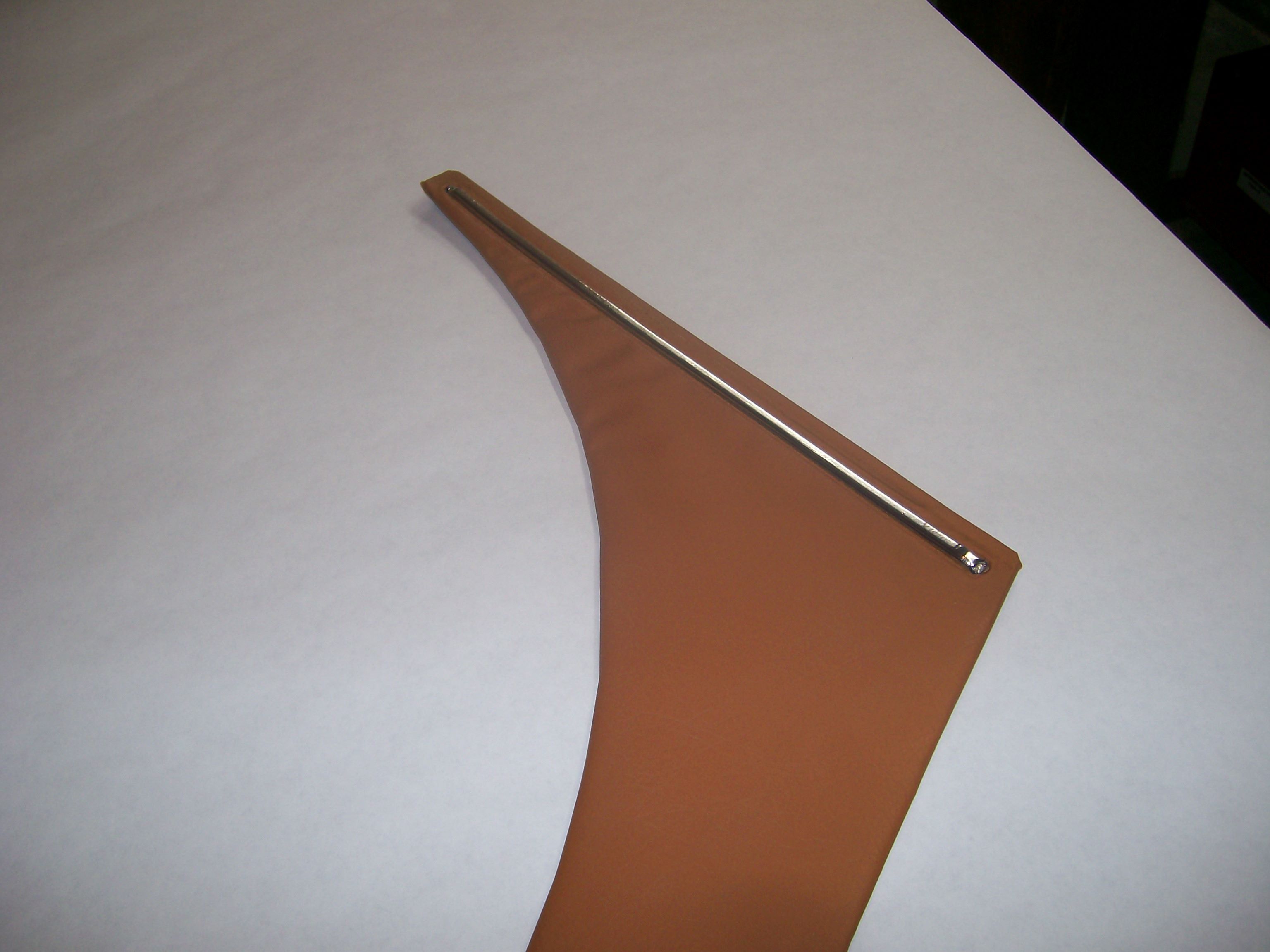
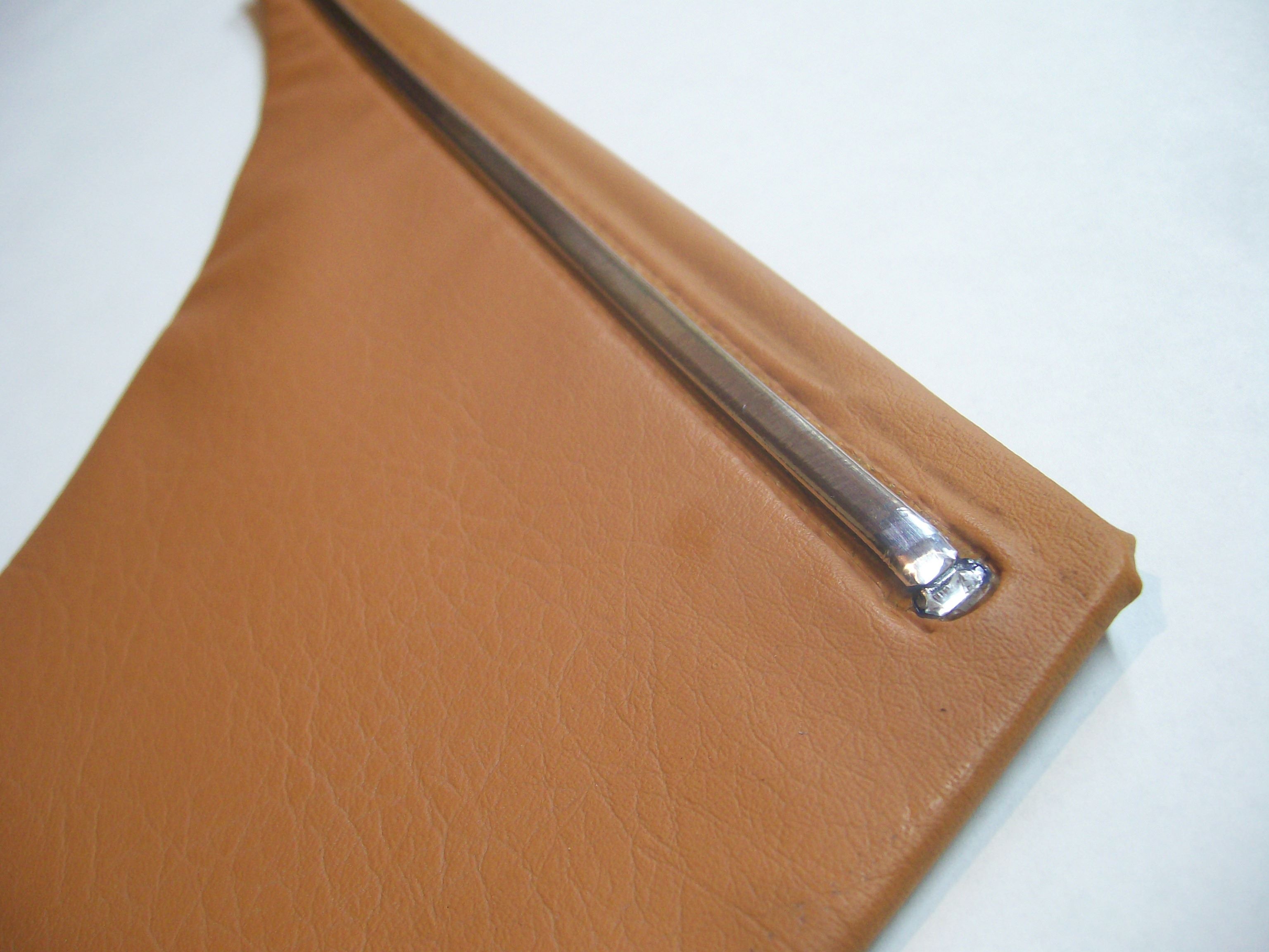
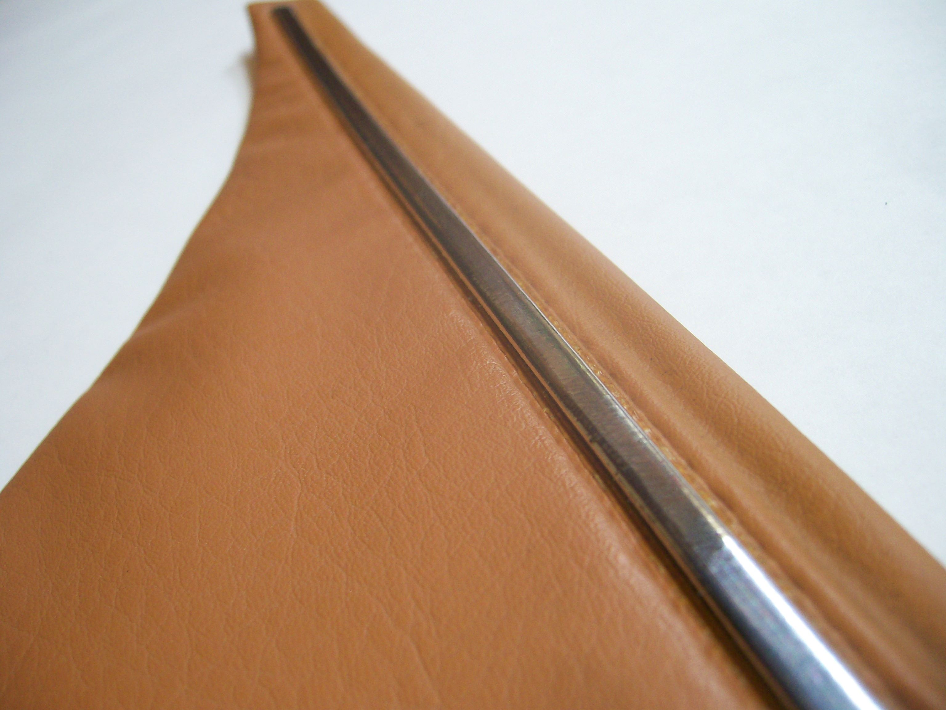
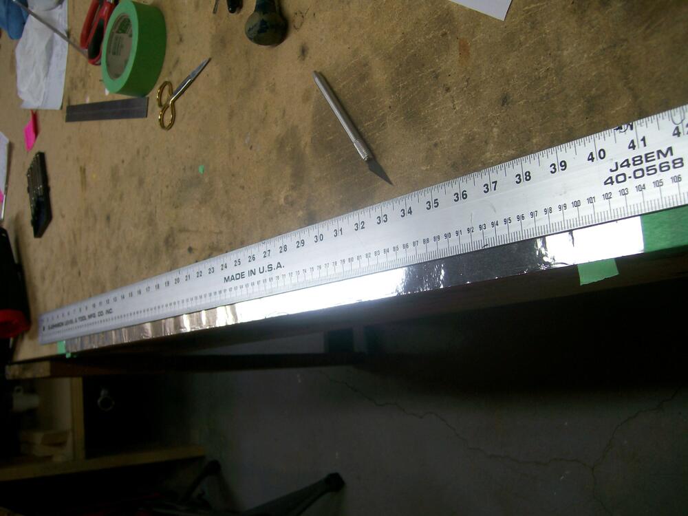
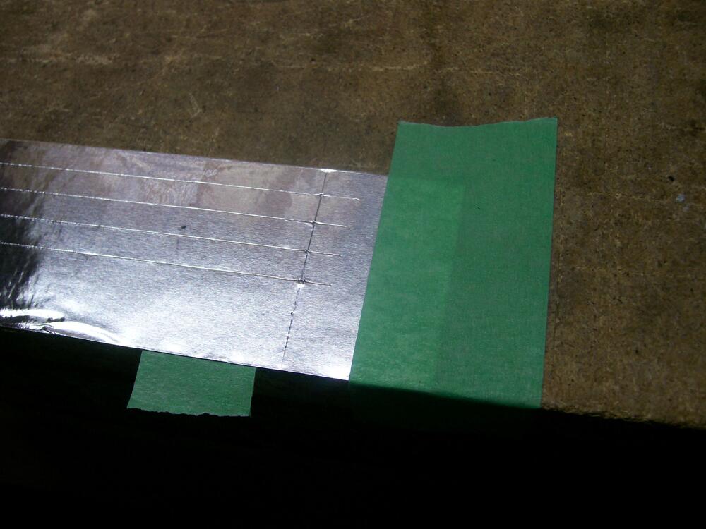
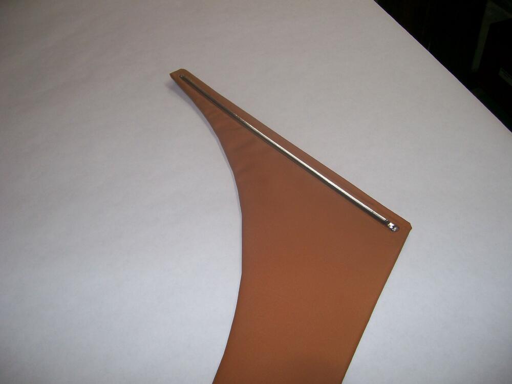
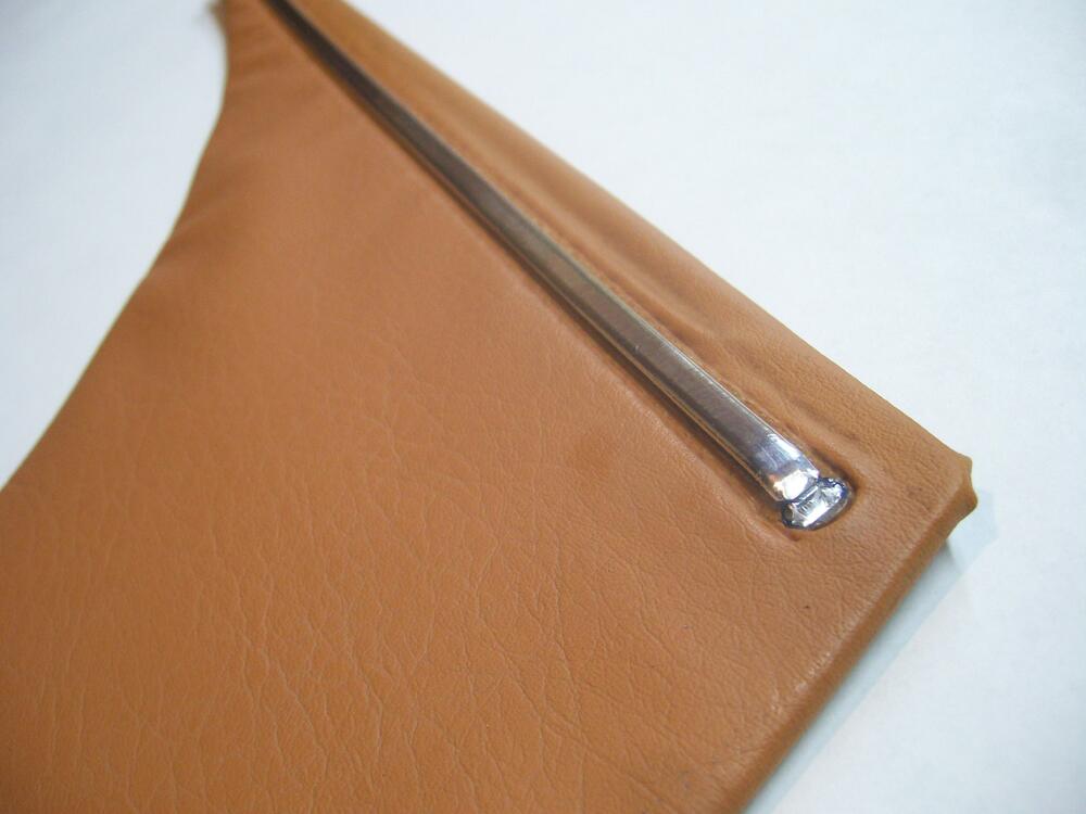
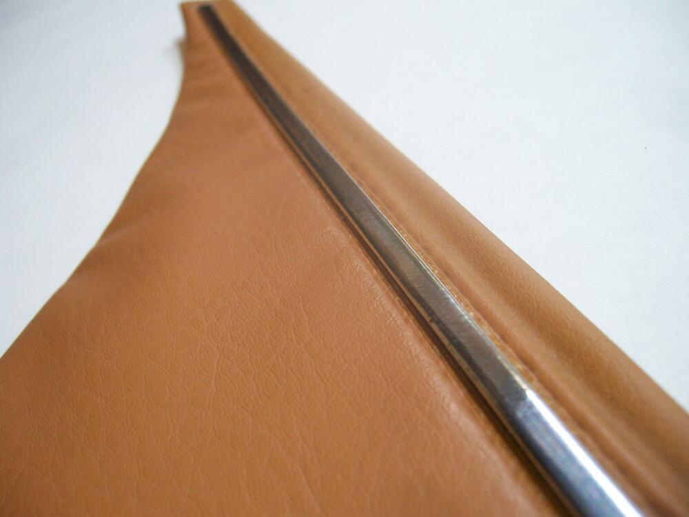
A few photos to go with my write-up. I didn't take any photos of the work that I did with my door trim panels. These pix show the same technique used for the rear kick panels...
-
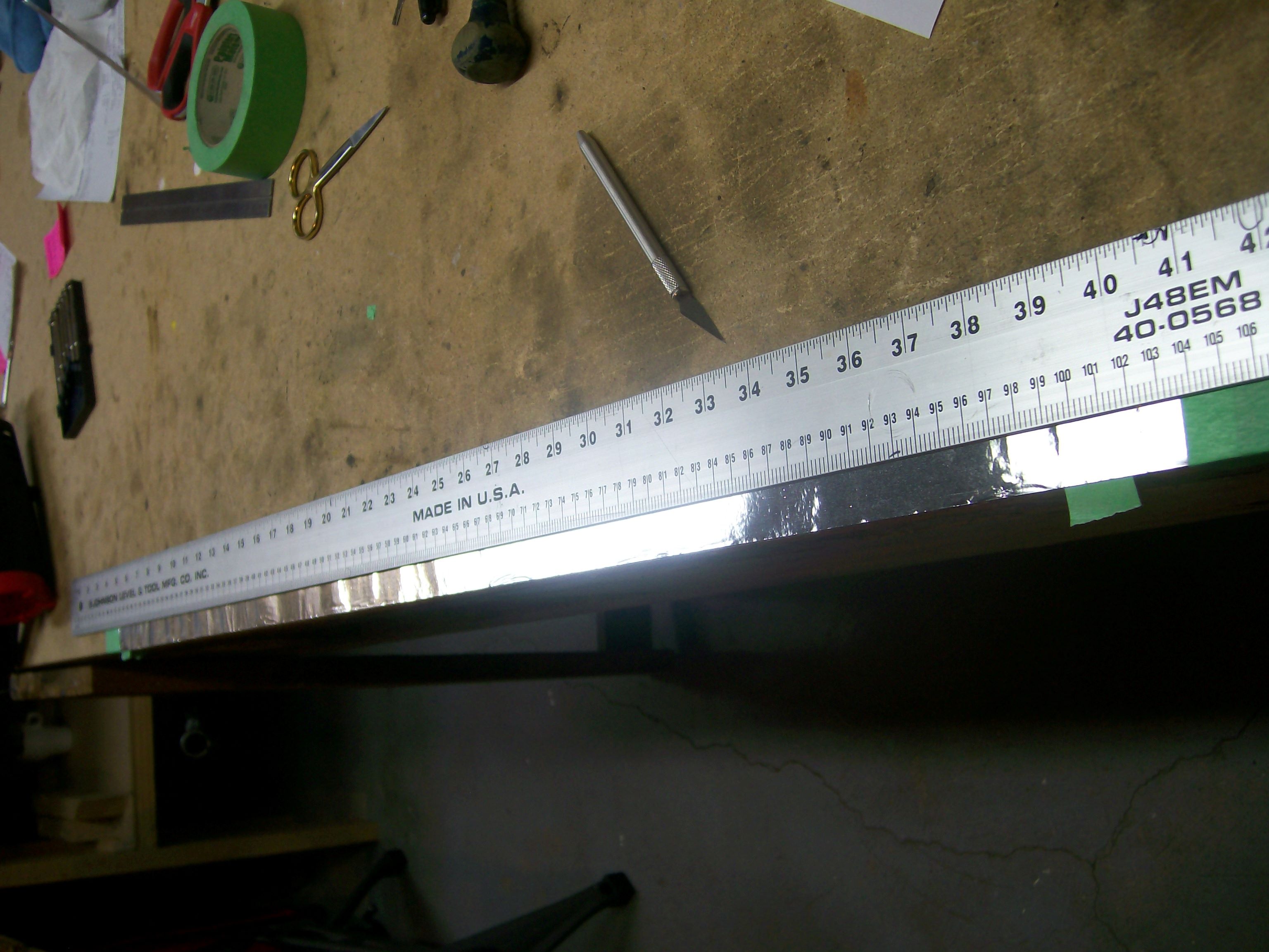
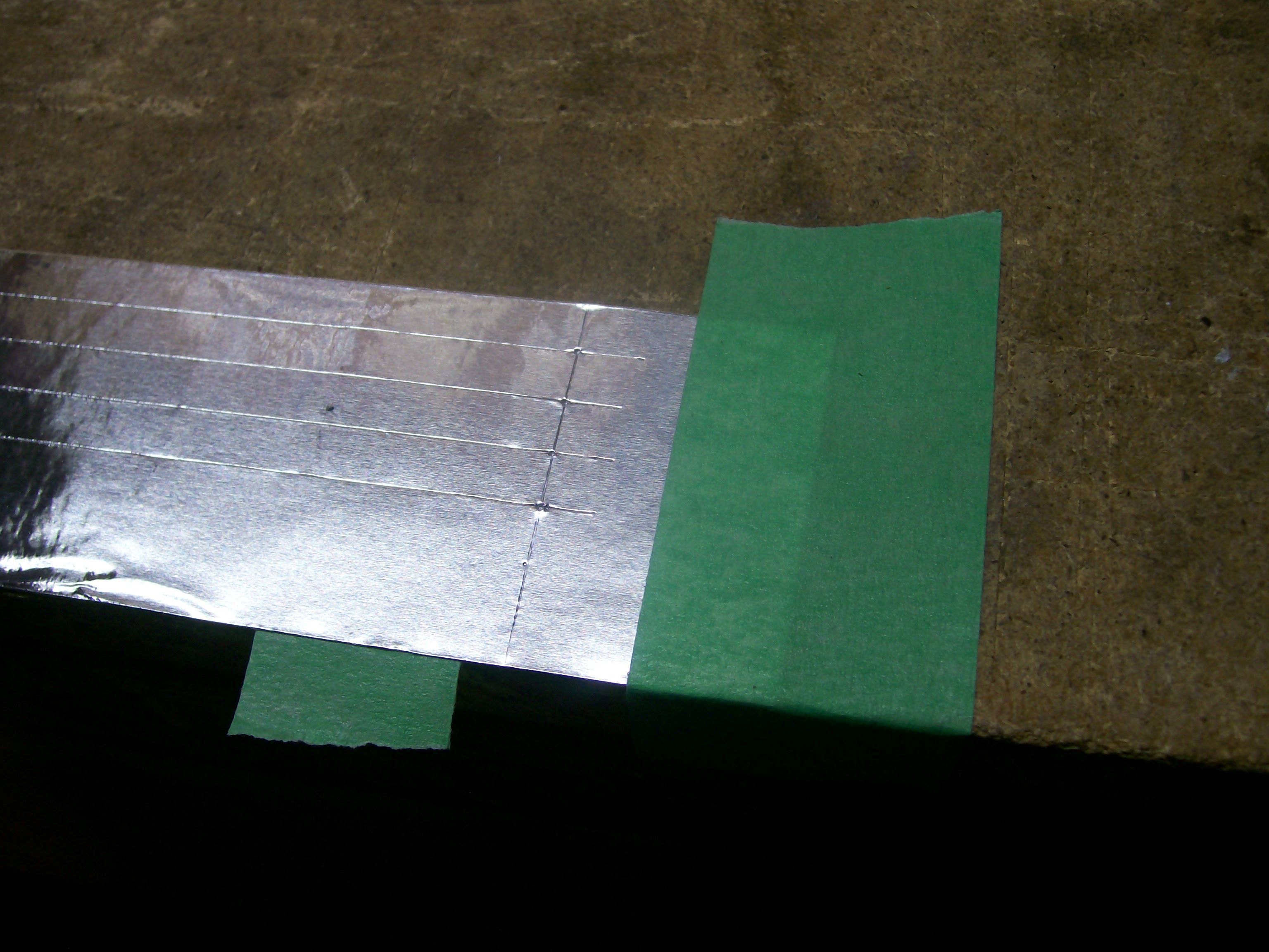
For your consideration: HVAC duct-sealing foil tape (adhesive backing) can, with care and patience, be used to replace the chrome film. The result has a finish that's almost indistinguishable from the original. I used this foil to restore my door cards and rear kick panels. Five years later, the tape remains securely in place. Steps: Leave the trim strip in place, but peel off the 'chrome' layer. It comes off as a thin film and you should be able to remove 100% of it without needing to use chemicals. Left behind will be the blue-coloured plastic strip. It has a 'D' cross-section. Measure the perimeter of that cross-section by shaping a piece of aluminum foil over the surface and marking the base of the 'D' on each side with an awl or straight pin. Flatten out the foil and take your measurement. I measured it at 9mm for the rear kick panel. I'm not sure whether it was the same for the door card accent strip. Cut a length of HVAC duct-sealing foil that's about 6" slightly longer than the door trim strip. Secure it to a flat surface, shiny side up, using regular 'duct tape' at each end. Mark off several strips, using the 'D' perimeter measurement to define the width of each strip. Using a long straight edge and a utility knife (with a fresh blade), cut at least full-length 6 strips (you eventually only need two, but you'll probably ruin at least two at the start as you practice stripping off the backing sheet and then applying to the door strip). For each lengthwise cut, work from the inboard edge of the widthwise duct tape at one end to the similar point at the other end. Then, after making your six lengthwise cuts, use a shorter straight edge to cut widthwise at each end. Tip: It helps if you clamp the long straight edge to the table/bench top, so that it can't move while you're making each long cut. Clean the surface of the blue plastic trim strip thoroughly. I used denatured alcohol. It's particularly important to get the top and bottom parts of the 'D' clean (where the strip meets the door trim vinyl). As noted, it takes a bit of practice to figure out how to pull the backing strip off the aluminum foil strip without putting a kink in the foil and/or having the foil accidentally bond to some unintended surface before you have a chance to start laying it down on the intended target (i.e. door card's blue plastic strip). It also takes a steady hand to keep the tape properly centered on the blue plastic strip as you lay it into place along the length of the plastic strip. The application technique is to lightly lay the foil onto the crown of the D. Press it into place at the front end of the plastic strip, then align while gradually lowering the full length of the foil down into place. It may take a few tries to get this right. Unfortunately, every failed attempt will ruin the foil, so you'll need to use a new strip for your next attempt. Once you get a good result, the next step is to cut the excess off at the front and rear ends of the foil. You'll need to judge the position of these end trim cuts so that, once pressed down, the cut end of the foil will align with the end of the blue plastic strip. Getting an acceptable result here requires a little additional work because the end of the blue plastic strip is rounded. The foil will not stretch to meet this contour. The only way to avoid a crinkled surface is to make two short lengthwise cuts so that the foil is now divided into three short segments. Eventually (but not now), you'll be able to press the center part down first, and then press the top and bottom segments into place. There'll be a slight overlap. Returning to the main job, your foil strip at this point is lying flat along the length of the blue plastic strip, touching only the crown of the 'D'. You now start working the foil down over the 'D' contour. Use a soft cloth rub lengthwise, gradually working the tape down over the 'D' contour. To avoid 'bunching', work from the center out to each end, rather than from front to rear. Work from the crown of the 'D' outwards, alternating from the upper half to the lower half. I think you'll be very pleased with the final result. My only caveat for this technique is that I haven't tested the effectiveness of the foil adhesive under extreme temperatures (e.g. car parked outdoors in the summer with the windows up). If you're concerned about this and think you know of a better adhesive, you could always try gluing chrome mylar film over the blue plastic trim strip. Personally, I like the foil because it's metal and actually bends to into shape over the 'D' contour, meaning that there's very little residual force trying to lift the edges. At extreme temps, the adhesive may temporarily get a bit gooey (technical term), but I don't think the foil will lift unless it's disturbed by the side of your arm. I take some consolation from the fact that this foil is designed to be reliable for use on air distribution ducts that carry both cooled and heated air.
-
'Performance improvement'? Please explain.
-
After looking at Sean's website, I was unable to find any mention of these parts (window trim pieces, oil pump gear). Did I miss something? If not, how did you learn that they were available?
-
When I re-built my heater box several years ago, I left all of these flaps in place. After cleaning up the inner and outer surfaces of the plenum and flaps, I sprayed the inside with a rust-inhibitor paint and then the outsides with matte black. I then cut replacement pieces of foam (adding an outside layer of soft vinyl for the pads destined for the big flap). If you go to the 'Resources' section, I think that my full write-up is still there. Also included at the time was a set of templates for all of the foam pieces (these were designed to be printed at 1:1 and then glued to the peel-off backing sheet of the foam). If you can't find these docs, let me know and I'll re-post them. It's finicky work, but doing it properly produces a heater/blower that works effectively and quietly.
-
I remember that post, but I don't have a link. Here's a compendium of articles that I put together several years ago on the topic. No mention of the forming spring. but a useful suggestion for simulating the 180-degree bend using a 90-degree coupling and a section of a donor hose (EFI?) that has a 90-degree bend and the right ID. S30 Fuel Hoses & Hard Lines.docx.pdf S30 Fuel Tank Vent Hoses - Rating the factory replacements - ClassicZCars.com - 2011.docx.pdf
-
Whenever I read these discussions about Goertz, I'm reminded of another 'design consultant' of the same era, Raymond Loewy (automotive credits include the Studebaker Avanti and the Greyhound SceniCruiser bus). Both were European ex-pats -- Loewy born in Paris, Goertz born in Germany. Both gravitated to the US -- Loewy to NYC in 1919, Goertz to LA about 17 years later. While Loewy's credentials included some university-level engineering training (which he apparently did not complete), Goertz appears to have had no formal technical training and his career appears to have been based on not much else beyond an interest in performing Euro-customizing of pre-war Ford sedans. Apparently, he rented a garage with a showroom in LA to build and sell his handiwork (I sense that all of this activity may have been backed by a family trust fund). Somehow, he managed to get one of his kustoms (named the 'Paragon') exhibited at the New York World's Fair in 1939, where I'm sure that it attracted the attention of Mr. Loewy. It's not entirely clear whether the two met by accident of by design, but meet they did and it would appear the Loewy -- Goertz' senior by about 20 years -- decided to take Goertz under his wing. Or maybe Goertz just pestered him for a job. Loewy is said to have arranged for Goertz to get work with Studebaker, but this might have been nothing more than a piece-work role as a design sub-contractor (Loewy's industrial design firm was big and had enjoyed a significant consulting contract with Studebaker going back as far as 1936). It's worth noting that Goertz, after the end of WW2, had decided to shift his base of operations from Los Angeles to NYC and in the mid-1950's was busy enamoring himself with Max Hoffmann, the principal US East coast importer of many European brands (BMW included). One wonders how this led to his involvement with the Type 507 project. So: Interesting that the two knew each other and collaborated in some fashion. With their similar European backgrounds, it's easy to see how a dialogue of sorts got started. I wonder what was going through Loewy's mind when Goertz started promoting himself as a consultant for the BMW 507, Porsche 901, and Datsun Z? Loewy had put together a major industrial design firm by the 1950's, with over 100 staff (Loewy had even been featured on the cover of Time magazine). Goertz does not appear to have ever got past the status of 'sole proprietor'. While both men were, I'm sure, relentless self-promoters, Goertz 'chutzpah' really stands out in light of his 'one-man-band-with-no-followers' status. As HS30-H has pointed out, it can be tricky to try to assign the origin of a design to any one particular person -- as tempting as that might be. As a noteworthy example, the design of the original Corvette String Ray is often attributed to a sketch done by Pete Brock (designer of the Shelby Cobra Daytona coupe) while he was a junior member of the GM Styling department, working under Bill Mitchell, in the late 1950's. While the Brock sketch certainly displays many of the design details that became hallmarks of the Sting Ray prototype, it would be incorrect to claim that Brock was the designer (and, to his credit, Brock appears to have never made such a claim). I suspect that Goertz -- like Brock -- produced a sketch for concept that eventually became an icon (the BMW 507 in Goertz' case). Unlike Brock, however, Goertz appears to have no hesitation in claiming status as the sole-designer. Or, perhaps more accurately, he never said that he was but never denied that he wasn't. The same would seem to apply to his roles with the Toyota 2000GT and the Datsun Z. BTW, Raymond Loewy claimed personal credit for some of the most hideous automotive styling exercises that I've ever seen. Perhaps his real talent lay in assembling a group of talented people around him and then promoting and managing their efforts.