Namerow
Community Member
-
Joined
-
Last visited
Everything posted by Namerow
-
It seems it's hard for some painters to un-learn what they've picked up in the insurance-driven collision repair business.
-
-
In your last photo, is the light-green panel (so-called 'K-box') a KF piece or is it something that you made on your own?
-
Colombia, as in South America. When I dealt with them in 2019, the sales office was based in Florida (Miami, IIRC), but the parts are stamped in Colombia. If you do a little snooping on line, you can find some pictures of the factory. They made their rep supplying the VW microbus community and then decided to branch out into other types of vehicles. Datsun and Toyota models were chosen to lead the way.
-
Without meaning to shill for this vendor, they have really taken the Z restoration process a completely new level when compared with the bad old days of Tabco-or-make-your-own. I just checked their website and was pleasantly surprised to see that they've pretty much doubled their range of Z repair panels from the time when I last checked in 2020 (the 240Z catalog now includes 44 items). Some of the noteworthy additions: radiator bulkhead front inner fender patch panels, c/w separate 'pocket' piece for the crossmember join area and separate 'doubler' panel for the K-box area firewall repair panels (lhs and rhs) battery tray - separate, or c/w inner fender patch panel dogleg repair pieces - inner and outer, plus lower B-pillar piece front fender lower-rear patch panels, c/w mounting details Worth a look. KF Vintage JDM 240Z Separate catalogs for 280Z, 510 and 620 (!)
-
Who makes it? Or, who was the supplier that you bought it from?
-
Here's an article on re-bushing the SU's that I found in my e-library. Credited to Delaware Valley Triumphs club member, Tony Rhodes (www.dvtr.org -- based in Philadelphia) . It provides some insights into the symptoms, the cause, and one of the cures (re-bushing). In essence, this approach assumes that the majority of the wear problem occurs in the steel bushing ('ovaled'), not the ends of the chrome-plated brass shaft. That seems counterintuitive, but I miked a set of worn shafts and found very little difference in the diameters of the unchromed ends vs those of the chrome-intact sections. Maybe someone else can verify by doing some measurements on used throttle shafts that they have on hand. SU Carbs - Rebuilding - Bushing Reaming.pdf
-
I wonder if Nissan had some build tolerance issues with the earlier cars' structures and used this strategy as a cheap-and-dirty way to get all three engine/trans mounts points to line up with the structure after the engine/trans was put in position (i.e. secure the transmission mount first, then bend the engine mounts to line up)?
-
Intriguing idea. Not so much 'outside the box' thinking, but more like, 'What if we turn the box upside down?' Some pix would be nice.
-
While the Z community is well served by a couple of specialty manufacturers of replacement body panels, there remain certain large panels that can usually be sourced only by taking a replacement panel from a donor vehicle. Examples would be the hood, roof, hatch, outer and inner door panels, firewall, inner front fenders, rad bulkhead, and the tail panel. Nissan has recently previewed a new technology that permits large, complicated-shape panels to be formed without a die. While it's probably intended to serve the collision repair industry, it's conceivable that they might be talked into doing short runs of panels for older classics like the Z and Skyline. Here's a video from the auto industry daily blog, Autoline Daily:
-
-
Even if CO had completed that undergrad course in fluid dynamics, it wouldn't have taught him anything about the behaviour of bubbles entrained in fluid flowing through a pipe. That's pretty specialized stuff. It definitely wouldn't have taught him anything about dislodging a bubble trapped in the corner of a casting. It's worth pointing out that applied science (engineering) is usually based on observing a behaviour first and then finding ways to apply the theory so that it generates a decent prediction. Grannyknot makes a valid point about the ratio of the bubble diameter vs the brake pipe diameter. However, even if the brake pipe was 1/2" in diameter I suspect that the bubbles would stay small and would still be swept along with the flowing brake fluid. This would be a great weekend project for CO: Build a demonstration rig using clear tubing and some drilled-out clear acrylic 'castings' and then pump some fizzy brake fluid through it to see what happens at the high points and inside the casting voids. Somewhat off topic, but microbubble technology is a pretty hot topic these days in the field of medical treatments and drug delivery technology.
-
Based on what I can see from the photos, it sold at a fair price. It might have pulled $15K on just the right day, but that rarely arrives on time. The floors need to be replaced. Maybe the front frame rails, too. The interior has been rode hard and hung up wet. Dash is really bad. Door cards are incorrect. Seats look shot. The sunroof is unfortunate. Most Z buyers don't want this and it's hard to restore the roof to as-new condition without grafting in a completely new panel from a donor car. We also don't know whether there may be collision damage lurking in the dark areas. The only offsetting feature that I can see the set of first-gen wheel covers. And even they need restoring.
-
You did a great job with that build, Chris. We all knew that you could cut and weld, but the paint job that you pulled off on the 510 in that small garage was truly impressive. It will be interesting to see what kind of price it brings. As they say on BaT, 'GLWTS'. For your next project... ???
-
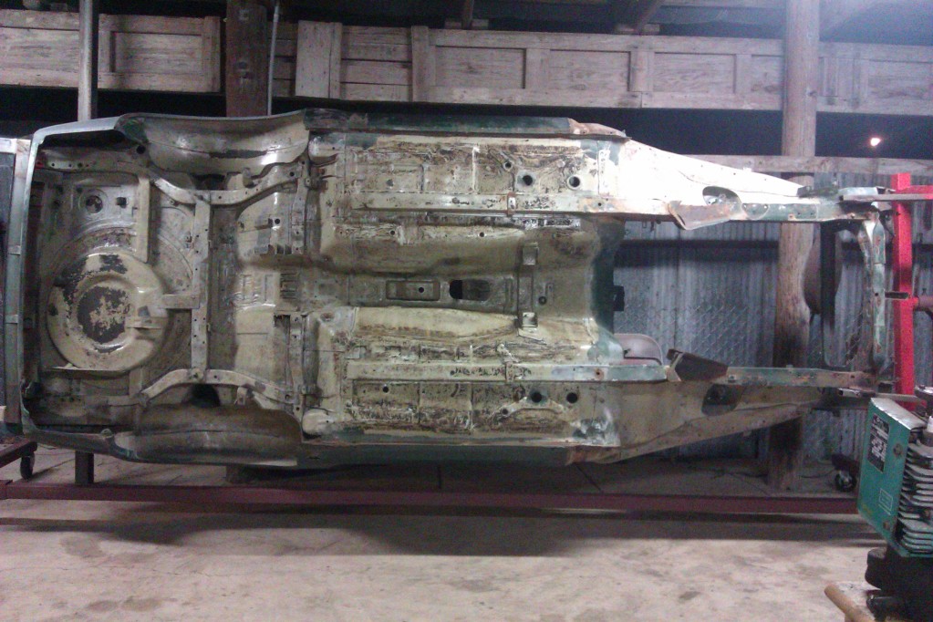
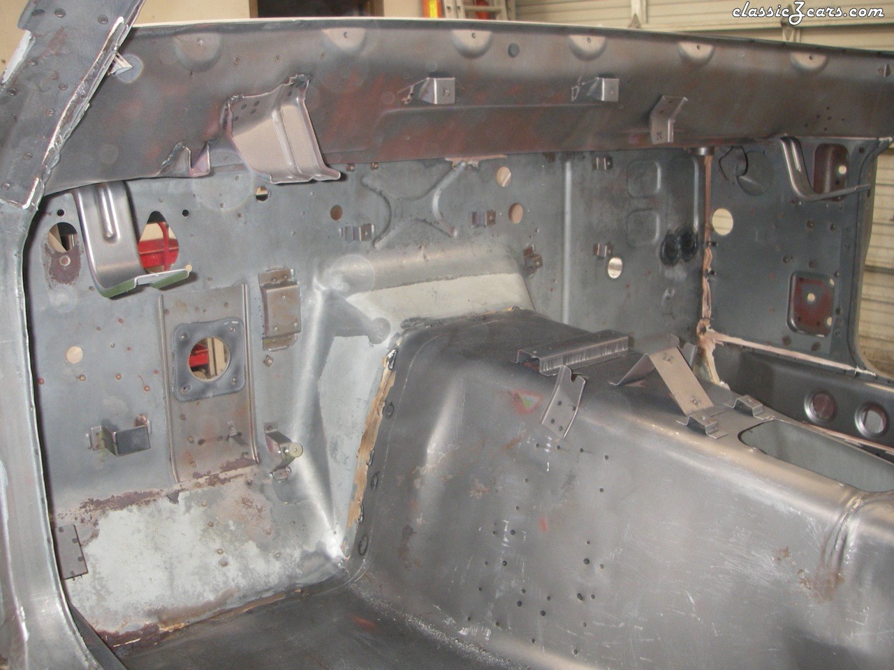
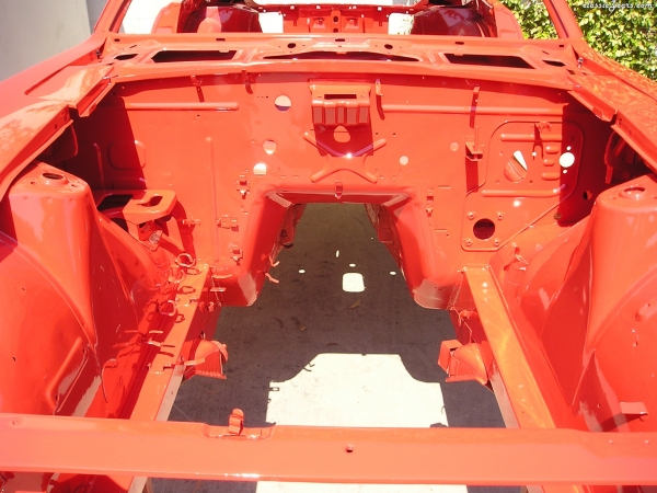
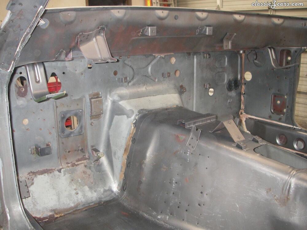
Grannyknot's explanation is on the right path and identifies a key part of the S30's structure whose importance is often overlooked: the transmission tunnel. Your question seems to be focused on braking loads (i.e. rear-directed loads that occur in the horizontal plane) and your supposition is that the rocker structures are the only elements of the structure available to absorb these loads. Were that true, than the braking loads would, indeed, need to be transferred to the rockers by the firewall panel. Not an ideal situation, as you've guessed. In fact, the braking loads are largely absorbed into the transmission tunnel (note: 'largely', not 'entirely'), which then distributes some of those loads out into the floor pans. The pictures below will, hopefully, help you to see this... The rocker structures may eventually take up some of the braking loads, too, but I don't think it's a very large component. The rocker panels' job in the structure ure that everything was kosher.

-
The company is Auto Panel Solutions, located in Thirsk, Yorkshire, UK. No website. They advertise only via Facebook. Prices seem reasonable and the CZCC members (not many) who have done business with APS seem happy with their purchases.
-
Patcon is correct. The 'inner fender' (which you might see as being the engine compartment side wall) forms the fourth side of the box. Thar inner fender panel has a horizontal flange along its bottom edge. For its part, the 'frame rail' has a vertical flange along its top surface. The frame rail is joined to the inner fender by two rows of spot welds: the first along the horizontal flange and the second along the vertical flange. I agree that it can be a head-scratcher until you stop and stare at the details.
-
There is no such thing as 'a good impact socket to fit the transmission bolt'. In fact, there is no such thing as 'a good socket to fit the transmission bolt' -- unless you buy the special 'double-square' socket that I recommended in my earlier post. A regular 6-point or 12-point socket is guaranteed to ruin a square bolt head. You'll be better off using a big pipe wrench. Also: When you're using the heat gun, you need to focus on the aluminum casing around the bolt, rather than on the bolt itself. The idea is to make the casing expand. It's not the same as when you're trying to break a bolt free where the threads are corroded. In this case, you're simply dealing with a big bolt that's been over-torqued into a giant, thin-wall aluminum casting.
-
Don't consider heat as a 'last resort' strategy. Instead, make it part of your basic strategy. As mentioned by someone else earlier, don't use a flame source (i.e. don't use a torch). Instead, use an electric heat gun (inexpensive, easy to find, easy and fairly safe to use). I would suggest that you heat the area around the plug for about 2 minutes. Then you can go with whatever wrench strategy you decide to use. The square-head type of plug (whether male or female) isn't designed for high-torque, so it's not too hard to round off the corners if you get sloppy. Make sure that you choose a wrench that fits as closely as possible. In fact, a pipe wrench (a big one) may prove to be the most suitable because these are designed to self-tighten (if you use them properly, that is). Another option is an 8-point ('double-square'), 1/2"-drive 17mm socket fitted to a 24" breaker bar. The type of socket that I'm talking won't be available at your local tool store. You can order one from Toolpan.com ($7.50), but it may be a few weeks before they can ship. No matter what wrench you choose, one of the challenges can be positioning. With a four-sided plug head, a pipe wrench can only be installed in four positions -- i.e. stepping around the plug head at 90-degree intervals. An open-end wrench is much the same, although they're designed so that the wrench end is about 10 degrees off centre, meaning that if the plug head is oriented at 12 o'clock / 3 o'clock / 6 o'clock / 9 o'clock then the wrench end will be at (for the 3 o'clock example), either 2:45 or 3:15, achieved by flipping the wrench over. The double-square socket on a non-ratcheting breaker bar will let you adjust the breaker bar position at 45-degree increments.
-
I like your wheel/tire choice and I like the stance as is (picture 2). Also the amount of wheel/tire 'fill' within the fender openings. The problem, however, is that your tire to top-of-wheel arch gap appears bigger the front than at the rear. I think it's a bit too big at the front and a bit too small at the rear. But maybe the shadows make it difficult to tell. If I'm right, though, perhaps the best starting strategy would be a half coil off the front and a bit more spacer at the rear. The visual part is subjective. Messing around with the suspension too much can have undesired consequences.
-
Mike at Whitehead is an honest, but busy, guy and not famous for replying to emails. I suggest you go old school and call him by telephone.
-
Was the OE bush split?
-
@zKars Are the OE bushings split, like this one appears to be? If so, it adds some interesting wrinkles to how the ID and OD specs should be interpreted.
-
I've never been very enthusiastic about poly bushings. I know they appeal to the 'go fast' group, but they punish the car's occupants on roads that are anything other than perfect. Here in the salt belt region, perfect roads are hard to find. With wide, low-profile tires, poly bushings in the steering will amplify every seam and step in the pavement and feed the result right back into your wrists. You may end up 'communicating with the road' a lot more than you really wanted to. That said, I see you live in North Carolina, so winter-damaged road surfaces may not be a concern. And if you're only going to use the car for occasional fun blasts, you probably won't be behind the wheel long enough to notice. Back in the day, a lot of 'enthusiast' owners decided that the original Z's steering system was too mushy. Before poly bushings arrived on the scene, the solution was to: 1) substitute a hockey puck for the shaft coupler bush, and; 2) shim the mounting faces of the rack bushings. While I don't recommend the hockey puck, you might consider the shimming strategy so that you can retain the rubber rack bushings. It's a low-cost (and reversible) strategy for reducing compliance in the rack mounting. A suggested shimming material: 1mm polyethylene sheet stock (no worries about rust).
-
My 5/70 also has this plastic clamshell motor cover. I wonder if Nissan switched to the soft-vinyl bag because it made the wiper system installation a little easier during the vehicle assembly process.