Leaderboard
-
Captain Obvious
Free Member8Points10,081Posts -
kats
Free Member7Points2,215Posts -
.JPG.cfcada9cf1c1b502df3f5f2f2ca3ff36.JPG)
SteveJ
Free Member4Points9,646Posts -

Zed Head
Free Member3Points19,238Posts


Popular Content
Showing content with the highest reputation on 09/02/2022 in all areas
-
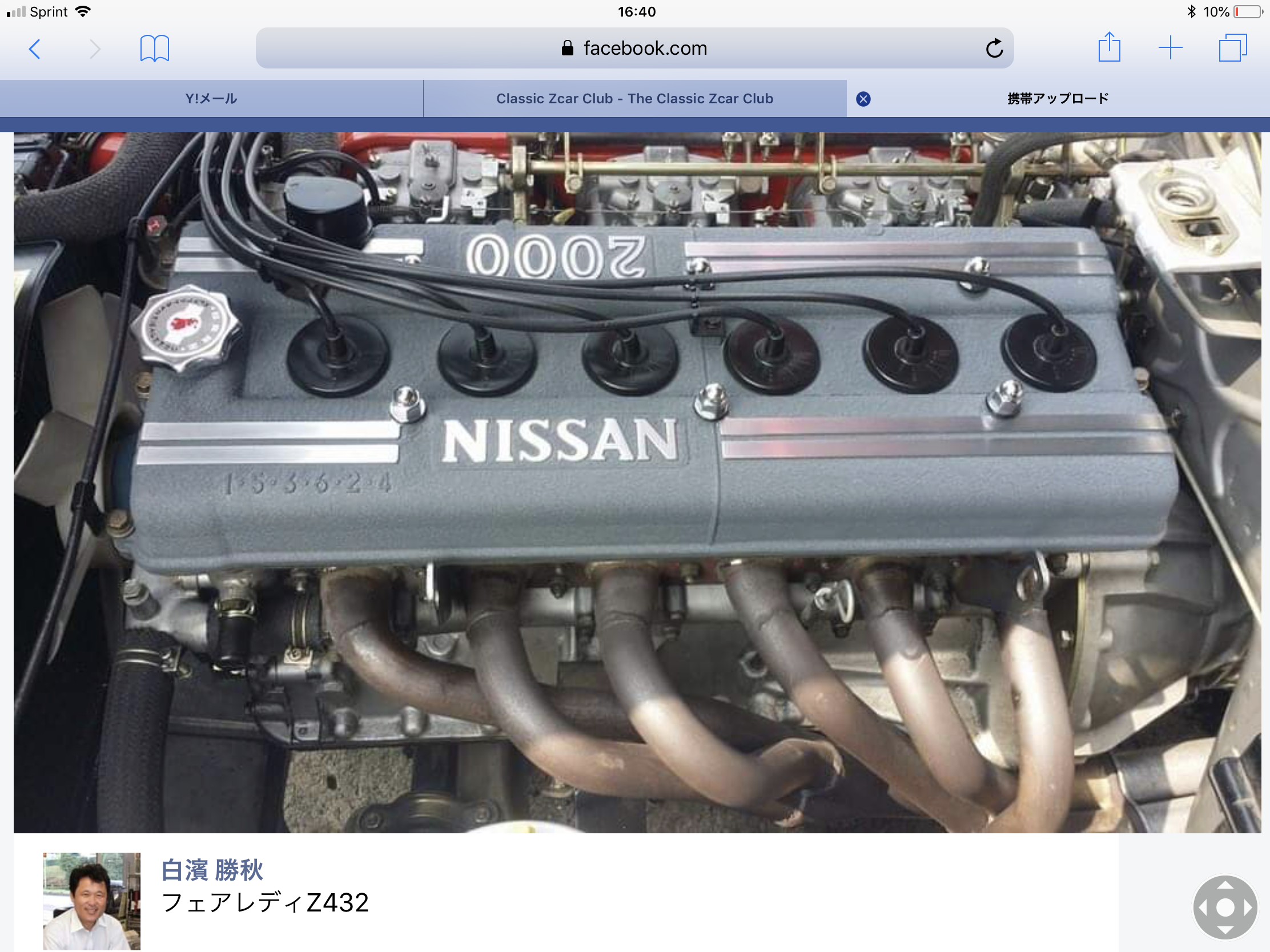
5 pointsToday I touched up a choke lever facia of HLS30-02146 . I have heard of ‘ GUNDAM MARKER ‘ which is a marker pen for painting ‘GUNDAM’ robot. I tried , and I am so satisfied with the results. To achieve the best results, sand it and get it smooth before painting. Kats IMG_7584.MOV FullSizeRender.MOV


 5 points
 -
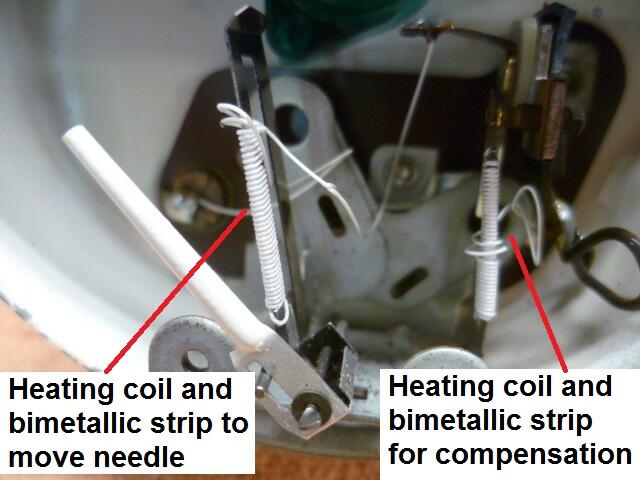
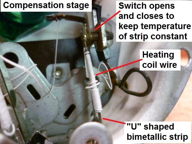
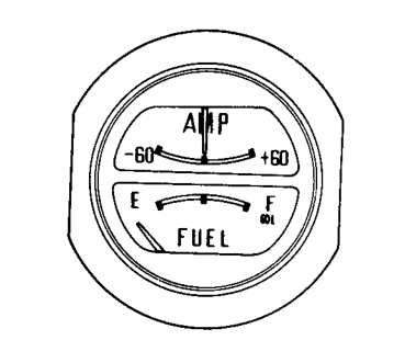
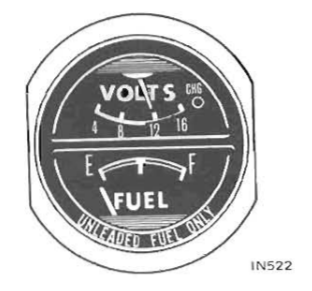
3 pointsHere's a pic of one of the gauges. You can see the two different heating coils wrapped around two different "U" shaped bimetallic strips. Interesting to note that internets research indicates that "U" shape is part of the compensation as well. The concept is that the unheated side will compensate some for changes in ambient temperature. "They say" it doesn't get rid of all of the temperature based effects, but it helps some. Between that "U" shape and the compensation stage, the gauges seem to be really stable. So this is an example of the compensated gauge with the two stages: And here's a closer-upper pic of the compensation stage showing it's parts: The switch opens and closes to keep the temperature of the compensation strip at a constant temperature (ave). If you put a Voltmeter on the sender unit, you'll see that it isn't a steady voltage, but is instead a square wave.
 3 points
 -
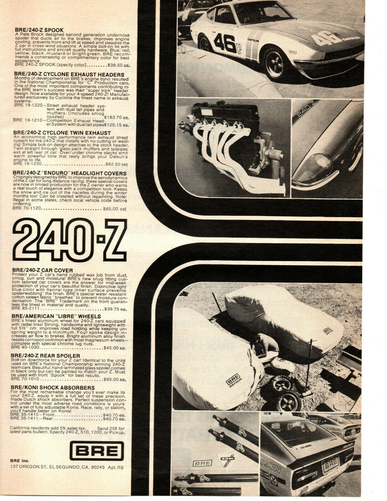
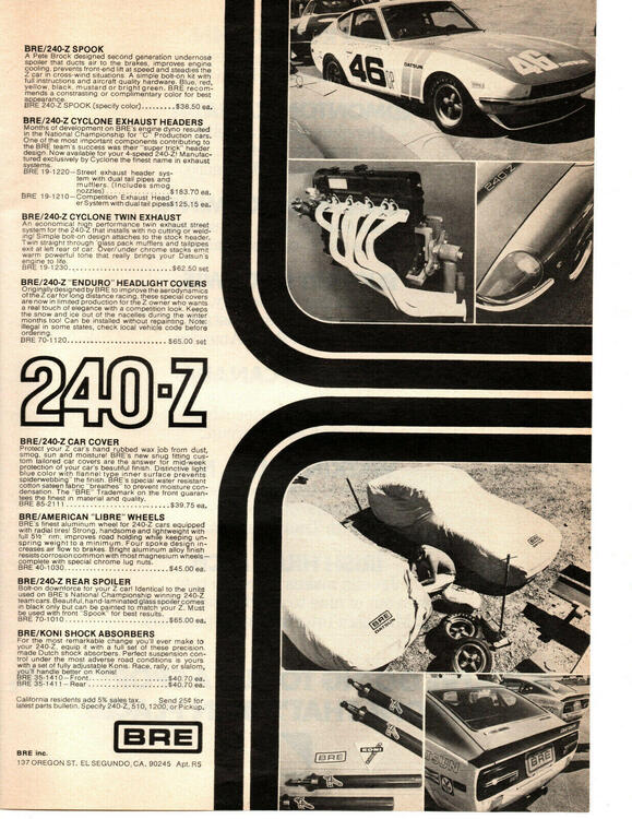
2 pointsAs an owner of a 1970 240Z with many original BRE parts fitted to it back in period by the original owner, I wondered how many other 240Z are out there so equipped. I found parts were sold by both BRE and later Interpart from 1972, covering every aspect of the 240Z from body to suspension and the engine as well. Seems everything from improved road performance to all out racer were catered for. There was a 1971 240Z on BAT recently that had lots of the original upgrades: https://bringatrailer.com/listing/1972-datsun-240z-177/

 2 points
 -
2 pointsI still have the BRE "Spook" front spoiler that I put on my '71 Z in 1972. It's no longer installed, but served well in holding down the front end at speed for many decades. It also worked fairly well as a an unintentional snowplow when I lived in Kansas.2 points
-
2 pointsDatsun put one regulator device in each of the gauge cases. So the TEMP/OIL gauge has one regulator that is in series with both of the needle moving heating strips, while the FUEL gauge has it's own regulator. Note that the AMP and VOLT gauges do not use a regulator because they do not use a heated bi-metallic strip to move the needle. The AMP and VOLT gauges use a D’Arsonval permanent magnet method instead of the heated strip, and hence do not need a regulator. So the TEMP/OIL gauge "can" contains one regulator shared (in series with) by both of the meters, and if that regulator develops a problem, that problem will show up in both gauges. As for what may be happening... If the shared regulator has dirty contacts and isn't making good contact, both gauges drop to zero at the same time. Note that the problem may be in the incoming power wiring and not the regulator at all, but based on the cyclical nature of the issue, I suspect the regulator. When it's stone cold, key just turned to ON, the regulator strip will be it's coldest and the pressure on it's contacts will be at it's greatest. Once that strip warms up and the system moves closer to equilibrium (PWM equilibrium), the contact pressure will decrease. I'm thinking when it's stone cold, the higher contact pressure makes a contact, but once it warms up and the contact pressure decreases, it goes intermittent. Of course, troubleshooting electrical stuff over the interwebs is never an exact science. But that's my read from a distance.2 points
-
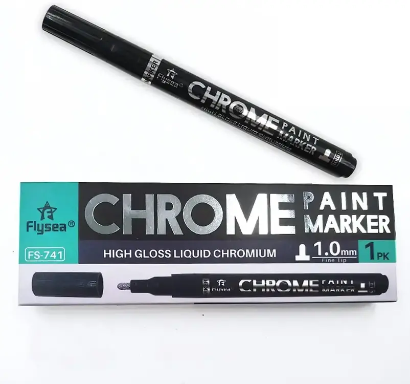
2 pointsI found similar results with CHROME markers. CHROME has different tips to choose. GUNDAM has colors; gun metal and a clear coat.
 2 points
 -
2 pointsSo the basic gauge system described above works, but there are inaccuracies caused by ambient temperature (cold day vs. hot day), and variations caused by system voltage (low alternator output voltage vs. higher alternator output voltage. In order to compensate for those real world conditions, the gauges are a little more complicated than the simple system described above. There are two "stages" to the compensated gauge. One of those stages is he simple gauge we already talked about above. The other stage is the compensating or regulating stage. It's job is to compensate for changes in ambient temperature and varying system voltage. The compensation stage consists of another heating coil wrapped around another bimetallic strip. This bimetallic strip forms an electrical switch such that when the strip heats up, it breaks contact. And when it cools down, it re-establishes contact. The trick is, that it makes and breaks contact to it's own power source and the power source for the simple gauge stage. The result is that this second strip/heating coil combo will make and break the power source such that it will always achieve the same average temperature. Of course the temperature is rising and falling some, making and breaking connection, but the AVERAGE is always the same. Colder day? Power to the compensation strip will have to be on longer to reach the temp that bends the strip to the point where it breaks the switch connection. Hot day? Just the opposite. Power will be on for a shorter time. Low system voltage? Again, power will have to be connected longer in order to heat the strip to the desired temperature,. And conversely, if the voltage is higher, it'll take less time. The result is that the compensation stage creates an ON/OFF/ON/OFF pulse train whose duty cycle and frequency will change depending on the ambient temperature and system voltage. This effectively creates a voltage source that will always supply a constant amount of POWER to the gauge system under all conditions. Clear as mud? Connect that constant power source to the simple gauge from above, and you have this: If you put your key in and turn it to "ON" you should see the gauges start to rise. Don't start the car. Just pick a needle and watch carefully. You'll see the needle start to rise, but probably before it reaches it's final position, it'll pause... Then start rising again. Then pause again. This will continue until it finally reaches it's final position. And even then, if you watch carefully, you'll see the needle actually wiggles a tiny bit. This effect can most easily be seen with a needle that's moving well above minimum like a full tank of gas. That pausing and wiggling is the compensation stage opening and closing.
 2 points
 -
The Youtube "short" only shows you starting the engine. Not much info in it. In your first post you were talking about volts but as I noted you should have an ammeter in your car, if it's a 1975. Are you sure it's not a 76? The build date can be in 75 for a 76 model. The voltmeter came in 1976. Do you have a hand held meter? Volts and resistance? If not you should get one. There are good options available for about $30. You need it if you're going to diagnose electrical problems. Here's an ammeter and a voltmeter. Not sure what you're working with.
 2 points
 -
1 pointA while back I found that there was an H4 headlight kit for the Toyota Land Cruiser that used Koito H4 housings. This got my attention since Koito supplied many bulbs to Nissan, including sealed beam headlights. The website I found with the best price said they were sold out, so I put myself on the waiting list. Earlier this week I saw a post on Facebook where someone said he bought this kit from Toyota for his Z cars and supplied a part number. Using that part number, I searched dealerships online that said they had the part. One of the dealerships is on the other side of town, so I pulled the trigger and ordered a set. The kit arrived today. It has a nice relay harness that I won't need. I am just after the H4 housings. I'll put H4 LED bulbs in them and install them in the 260Z. If you're interested in a set of Koito H4 housings, the Toyota part number for the kit is 81110-60P70.
 1 point
 -
1 pointSure wish I could find a Interpart rear window louvers set like I had on my '73. Install required no drilling, top had hinges and the bottom had little latches and there was a kickstand for the louvers so you could wash the window.1 point
-
1 pointIt would be about as difficult as replacing a sealed beam headlight. Wait! There's a video for that...1 point
-
Got my nubbins!! They look good. Have a major issue though. My wife threw away my springs. WTF!!!!!????? I have no words. Anyone know where I can get these or do I need to find someone to manufacture springs. I found this company - https://www.jamesspring.com/our-capabilities/compression-springs/
 1 point
 -
1 pointI just bought a pen on eBay and will have it shipped here, I've got a couple of steering wheel horns to restore along with Hitachi Radio surrounds and centre choke assembly finisher panels in my S30Z's. Also my door cards are missing the original chrome vertical line. I was going to try chrome tape, but this might be just as good! If anyone else is looking the code for the product is XGM100 and I found a cool video review showing how good the chrome can look here also.1 point
-
1 pointThanks Gavin, this time I skip doing prep , So it is not the best . Next time I will take care much better than this , I will see more shining chrome . It is really fun to paint ! Kats1 point
-
1 pointCool, I've used a Silver sharpie before for similar but that looks more "chrome" like the original.1 point
-
1 pointhttps://www.classiczcars.com/forums/topic/64427-no-oil-pressure-after-rebuild/#comment-6072211 point
-
1 pointI don't know how the internal "voltage regulator" works but Nissan said if both gauges go bad at the same time that's probably the source of the problem.
 1 point
 -
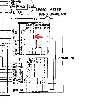
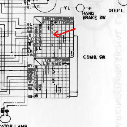
The headlight circuit wiring changed some time during 71 or between 71 and 72, I believe. The original circuit had the headlight switch completing the path to ground from the high/low beam switch as shown in the 70 and 71 FSM. In 72, the headlight switch controlled the wire going to the fuse box. (white/red to red wires) The high/low beam switch connected to the ground wire instead of going through the headlight switch. This later design was used for the rest of the S30 run. The change in the 260Z on is the type connector used at the headlights. I periodically search to see if anybody has found a source, but I haven't had any luck so far. Dave mentioned the wiring change in the headlight circuit to me many years ago, and I dug through the wiring diagrams to understand what he was saying.
 1 point
 -
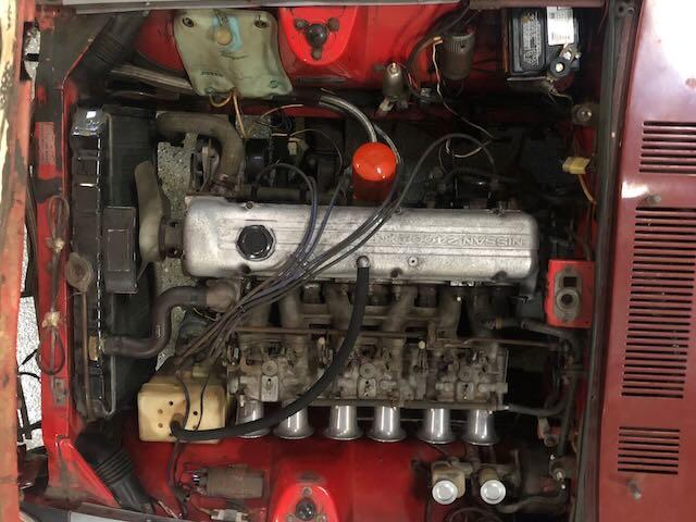
1 pointSome kind of rubber sealant they used to keep the joints from leaking around the frame. I cleaned it off and duplicated it as best I could with Ultra Black RTV. Seems to work ok.1 point
-
1 point
-
Why replace the alternator without testing the charging system, the starting system, and load test the battery? Simply guessing and throwing parts at a car is the worst way to go about troubleshooting. Test, prove what is malfunctioning, repair, then test again. That said, follow the testing procedures in the service manual. Find the problem and correct it. Most auto parts stores can test the alternator and the battery, to either confirm they are serviceable or not. Testing the voltage regulator should be covered in the service manual, and can be done with a voltmeter.1 point
-
So $2250 sold; BIN was $3144. Serious money for seats but they look perfect. Just like new. That seems like a reasonable price for what NOS seats would cost1 point
-
Charging problems with two alternators first points to the voltage regulator, especially since you didn't say whether or not you changed it. Keep in mind that if the voltage regulator is original, it is adjustable. The EE section of the FSM has the procedure. In addition to the link @kickstand80provided, you can download the FSM from here: The EE section is available, but unfortunately some other sections are not. (This applies to either download site.) If the voltage regulator is not an OEM part, it's probably time to replace it. You should test the alternator first, as was suggested. It looks like MSA has the best price for a VR, https://www.thezstore.com/page/TZS/PROD/12-4083. You may want to bite the bullet and order it today so it ships before they are closed for the long weekend.1 point
-
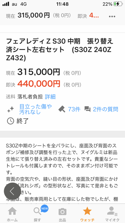
Hi Patcon , the winning bid was 315000 yen , the buy it now was 440000 yen . Bidding rule is a bit different from eBay . I think it is a god price for those nice seats . Now JPY is weak against US dollar, it might be a good timing for foreigners. But I think people in overseas don’t need to pay such a big money for seats , do they ? Or if there is an exceptional high quality of S30 seats , it might be different. Kats
 1 point
 -
1 point
-
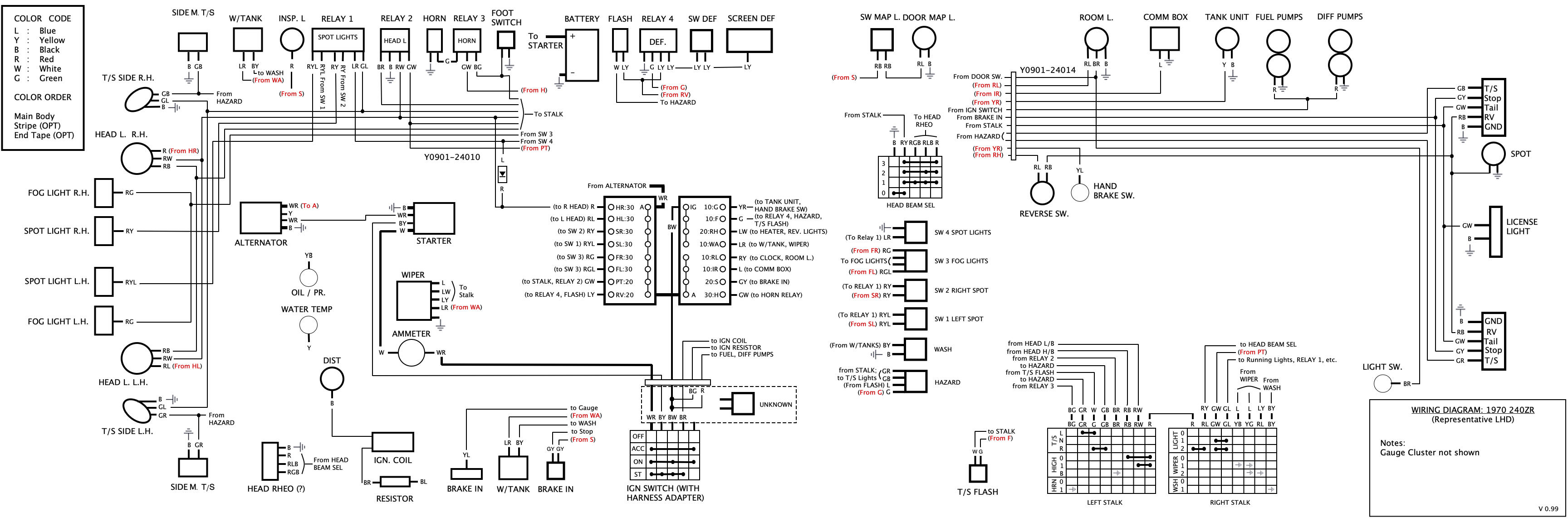
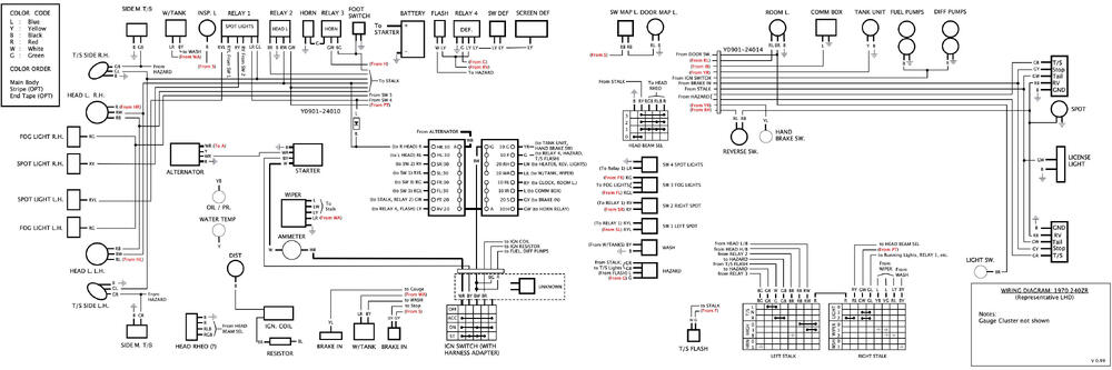
With respect to the CDI - the car currently has a special points-based distributor on it, which is the same kind as found on another Works car, and is potentially the same as an early L24 distributor, AFAIK. I've mapped out the entire wiring harness as shown below - this harness is in 2 parts (split at the fuse boxes) and has 2 Works part numbers, and date codes of 9/70 and 8/70, respectively. On the assumption that the wiring harness gets installed first, I've used this information to date the Works build as likely being 9/70 to 10/70, which would give the team about 45 days to test and ship the cars off to Monte Carlo. This particular harness contains no additional wiring to accommodate a CDI, as would appear in a Z432 with CDI of the same era. That said, there has been some private discussion about whether a CDI was used via an alternate means, as there is evidence of it's use in similar period Works cars. In the case of my car, it's use would likely be facilitated via a separately wired harness, which is no longer with the car. As to an interface to the existing harness: there is a missing 6" sub harness at the steering column that has been replaced with a later-period custom harness. This could very easily have been the junction point where a CDI could have been connected, as much of the relevant wiring would be there. This is marked as "UNKNOWN" on the wiring diagram. It should be noted that this is just pure speculation at this point. FYI, the above is my most current information, based on what I've already mapped out. It's entirely possible we may find more wiring surprises buried under the dash when we start the restoration process. Barring any revelations re: CDI, I'll likely restore it as-acquired, without it.
 1 point