Leaderboard
-
zKars
 Subscriber
 5Points3,770Posts
 -
.JPG.cfcada9cf1c1b502df3f5f2f2ca3ff36.JPG)
SteveJ
Free Member5Points9,646Posts -
dutchzcarguy
Free Member3Points2,677Posts -

Jeff Berk
Free Member2Points620Posts


Popular Content
Showing content with the highest reputation on 10/17/2021 in all areas
-
You have to be careful bench testing the fuel gauge. From the positive wire going through the gauge, there are two paths. One goes to ground, and the other goes through the fuel gauge sending unit and then to ground. Some people don't ground the first path and ruin the gauge. Power for most of your circuits goes from the battery to the ammeter and then down to the various circuits. (The brake light circuit is a notable exception.) If the wires at the ammeter are not going through the ammeter or not connected to each other, you're not going anywhere. As @zKars warned, if not using an ammeter, you have to insulate the connection between the two wires well, or you may end up with a smoking pile of rubble.2 points
-
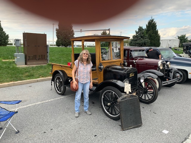
2 pointsGee, someone who knows what they're doing has had their hand in this presentation! Congratulations Again Jim
 2 points
 -
As long as you joined the ring terminals that were on the ammeter posts, then everything should work just fine. If you left them separated (and insulated I hope!) then ain’t nothing going do much of anything.2 points
-
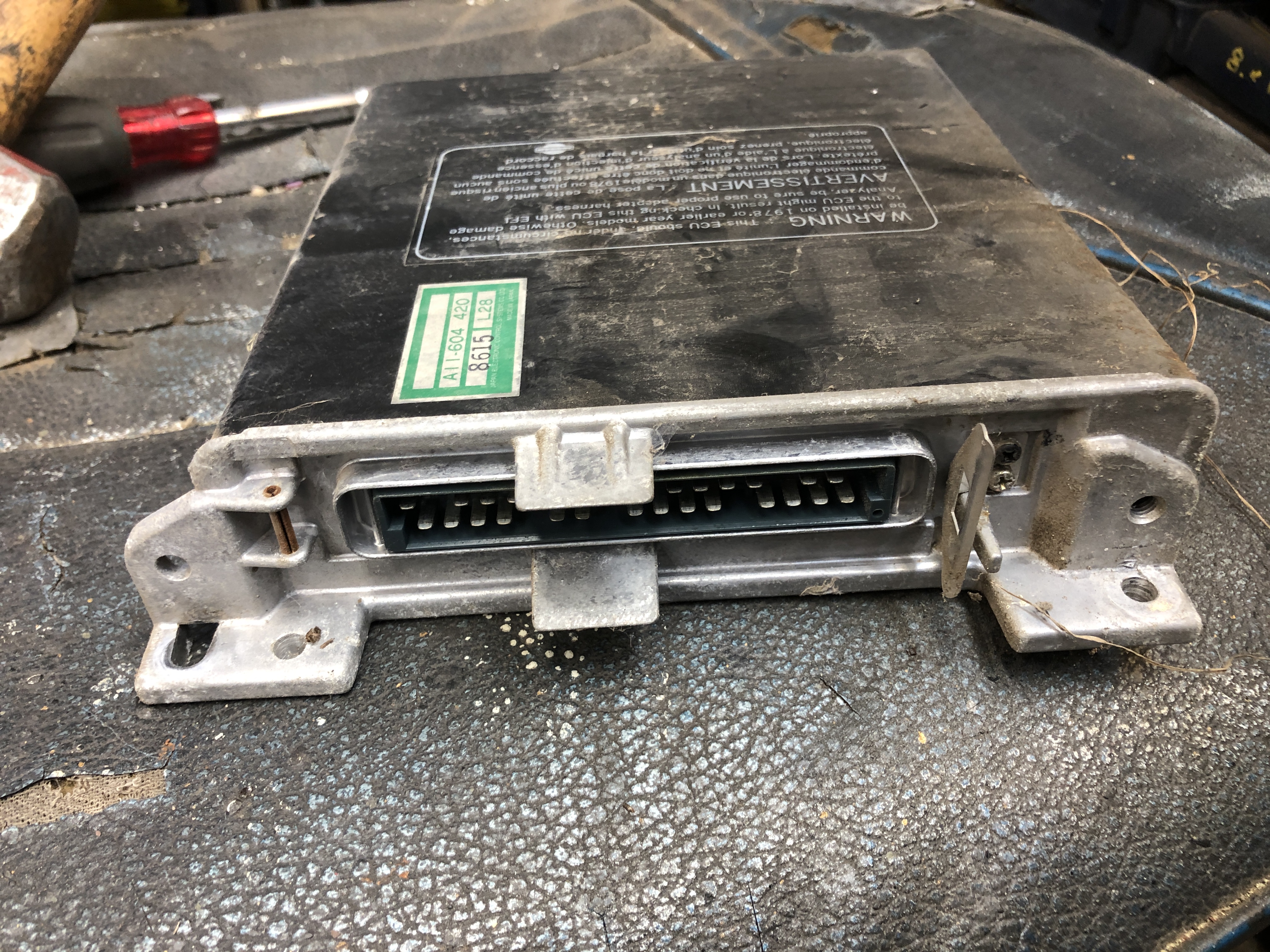
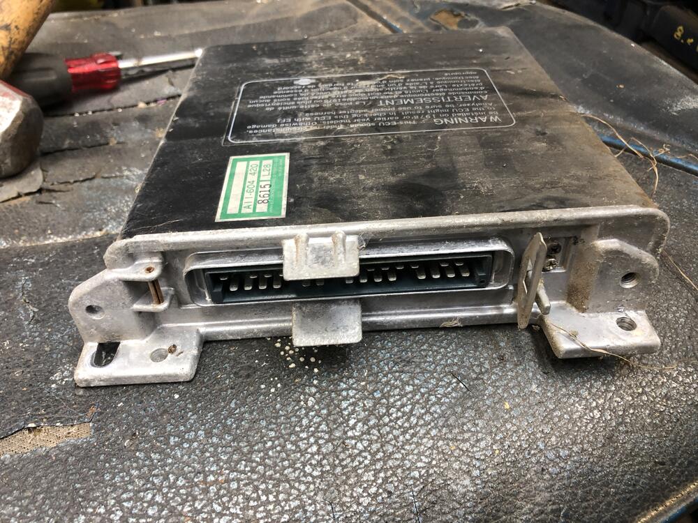
I just finished parting out what was left of a extremely rusty 79 slick top 2+2. I have the AFM and ECU if you want them for spares. Very very cheap. Only other things worth saving were the instrument cluster, steering wheel and maybe the right tail light.


 2 points
 -
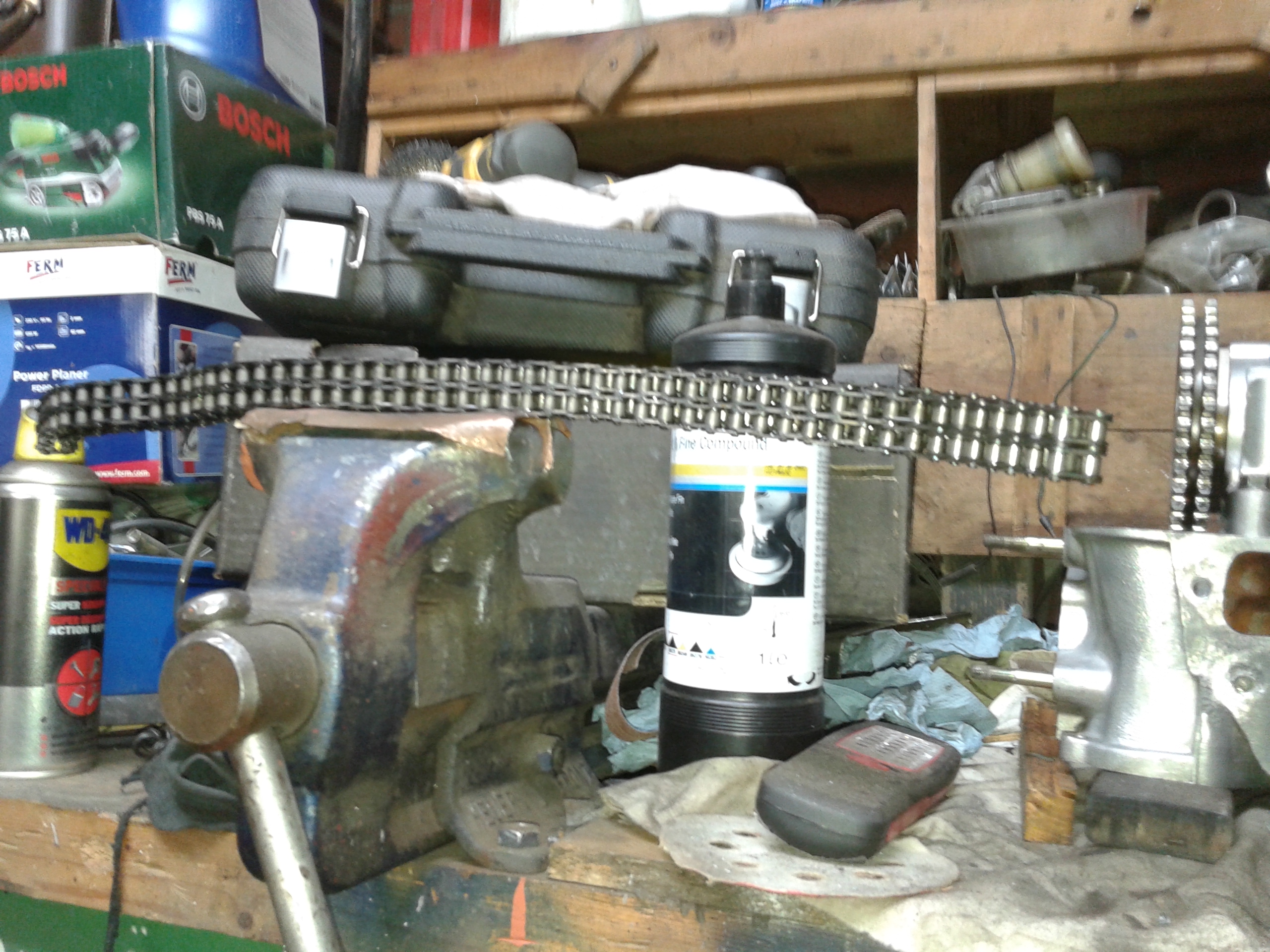
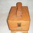
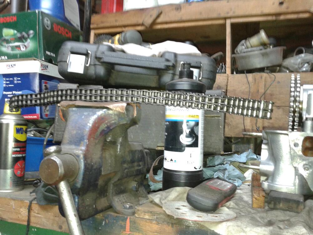
2 pointsAs i'm just in the proces of closing the front of my L28 (last week) I have a nice pic for you.. This is my reusable chain of 42 years old and 120000 Km on it ! It's in excellent condition if you ask me , By laying it on the vice you can see how much it bends.. this is normal for a used chain.. If it bends much more it's gone.. (I put it back with the big camshaftgear still on number 1 ! Meaning there is no stretched chain here..)
 2 points
 -
2 pointsI have the same problem with Pinterest and it's gotten to the point where sometimes I add -pinterest to the search to try and filter out Pinterest results.2 points
-
1 pointI was also looking at a 93 Honda Civic wiper motor on RockAuto.com. It looks the same as what ZCarDepot has.1 point
-
Now THIS is the way to frame a request for help. If you are worried about having a short that will fry the fusible link, there are several ways to assess the risk. Remove the fusible link and use a voltmeter and measure from the wire coming off the solenoid (for the fusible link) to the positive battery cable. If there is not a short, that should read 0V Measure resistance between the wire coming off the solenoid (for the fusible link) to ground. If it reads less than 10 ohms, you have a significant load or short. If you have less than 1000 ohms, you will have a pretty good battery drain. Use a 12VDC test light between the wire coming off the solenoid (for the fusible link) to the positive battery cable. If it lights up, you have a short. (Be sure to test the test light across the battery terminals to make sure you have a good bulb.) I would post photos with examples, but I have a gas tank sitting in the way on the garage floor right now.1 point
-
1 pointHi all, My restoration finished and with it my refreshed L28 picked up a Steve Bonk cam and a full head port and polish with intake matching by Reg Samuru. The cam has a great tone and idle and winds right up fast. I definitely notice more grunt mid range (where I drive) and overall am very pleased with it. The head was fully ported - and I do mean ported. Intake and exhaust had a lot of metal taken out an my intake was port matched, including locator pins on the head. Overall it is flowing more air, as measured by the increases in jet sizes to maintain nice AFRs (13.5 ish). There are lots of options out there but do consider reaching out to Steve in Chicagoland and Reg in Edmonton, AB, Canada.
 1 point
 -
1 pointHey guys, I know I'm late to the party here and it's probably been discussed but I finally got my Honda motor to function properly on my late '78 Z. It does it all! Intermittent, low, high and parks it correctly when turned off. I am happy to give complete details but basically it will work without adding any relays or disconnecting anything. I bought the motor from zcardepot and a used connector from ebay. This motor has a 5 pin connector and the Z has a 6 pin. The Z connector wires change colors at it's connector. These are the colors on the harness side, not the original motor side. H=Honda connector, Z=factory connector (H)grn/blk=(Z)blue/rd (H)blk=(Z)blk (H)blue/yel=(Z)blue/yel (H)blue=(Z)yel/blk (H)blue/wh=(Z)yel Leave(Z)yel/grn disconnected1 point
-
1 pointIt lets me browse the profile, but pesters me at every turn to log in or create an account. No.1 point
-
1 pointOh i love to see a pic like mine of a new chain.. i bet it's almost the same.. (It took some time to get the chain lying on the vise as it's very oily and flexing all the time.)1 point
-
1 pointThat is a very ingenious way of measuring/gauging wear on a timing chain. It doesn’t say much about stretch, but it does say something about pin wear. I’d have to compare it to a new chain to get idea of how much deflection is meaningful. Given the pretty reasonable price of a timing set (gears and chain and tensioner) I wouldn’t hesitate to put in a new set if I had the engine apart. I’ve never ever heard of a chain breaking, and stretch just means some mild adjustment of cam timing. At the extreme end of stretch you risk skipping a tooth or teeth and having your valves have a new angle on life (a very short life after that), but that is also extremely rare.1 point
-
1 pointyou can remove the front cover without removing head. as mentioned drop the front of the pan about 1/8 inch. if you want to inspect the bottom of the tensioner then removing the front cover is best. Make sure you get a good seal around the water passages. permatex aviation sealant. also you want good clean surfaces when reinstalling. lasty use a thread sealant on the water pump long bolts.1 point
-
Hmm, maybe they got the coolers because of the higher speed roads available in Europe. Sent from my iPhone using Tapatalk1 point
-
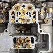
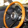
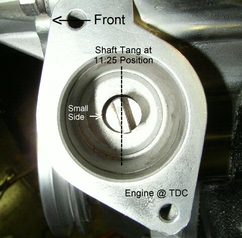
If you turn it full clockwise and idle doesn't raise I think you're spindle drive rod is out of time too. At 0 dead center the dizzy end of that spindle should look like this pic.
 1 point
 -
1 point
-
1 pointBoth are on Facebook and home based Datsun guys. All my dealings were via FB, FB Messenger, and texts. Who needs a website anymore? Thanks. I wonder if these guys know that by using only Facebook they are limiting their visibility to potential customers. I don't know if Facebook knows that I have an account because of my email address and are trying to force me to sign in, or if those pages are closed to everybody without a Facebook account. Either way, I could not look at the page without being a signed-in Facebook member. This isn't a comment meant to imply anything about the Facebook users out there. It's popular. Just pointing out the fact that the way it's set up forces users to join and sign in if they want to see Steve Bonk or the other guy's products. They might not realize that. Pretty fascinating how much control Facebook has, without people realizing it.1 point
-
the spindle that came out with the oil pump sets the timing on the distributor. I expect your ignition timing is advanced. there are many threads on here about timing the oil pump and distributor spindle.1 point
-
fast crickets are the secret to more HP. Keep that a secret you are not supposed to tell people about the fast crickets.1 point
-
1 pointWally-your new alternator looks to be the same design as the one I have, from ZCarDepot. I feel compelled to reiterate this: I also connected the + wire of the car to the ground of the alternator. Luckily, your fusible link worked; on mine, the wire maintained integrity, and burned off the insulation. The rub there: I think it's highly likely I have a short on the +wire to alternator that is hidden in the wire wrap. This seems to be a pretty serious safety hazard, especially if a fusible link doesn't blow. If I were you, knowing you definitely put those wires under a similar duress I put mine under, I'd check the sheathing on your alternator + and ground wires, at least with a DVM. (can anyone report back what an ideal impedance reading would be from battery harness + to alternator wire ground?)1 point
-
1 pointNo, there will not be a lot of leftover wiring. I'm not sure what you mean by extra wires. Pertronix has the basic instructions on their website for installing the ignitor. It shows where each of the wires from the ignitor should go. Notice the specifications. A resistor in series, like the ballast resistor, will drop the voltage. The voltage should still be within specs for the ignitor. The intent of the ballast resistor is for protecting the points. The condensor at the coil also contributes to the protection. However, with the ignitor, you no longer have points. So should you get rid of the resistor? That's up to you. However, you don't just leave the wires dangling in the engine bay. The wires at the ballast resistor have to be connected together if you bypass the resistor, otherwise, the car won't run.
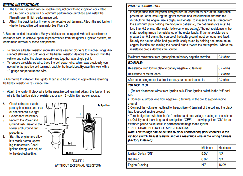 1 point
 -
I am soon going to get the 240z I have been working on for a couple of years painted. It was originally 901 silver. My plan is to have the painter paint it like the factory did it. And so, I'd like to confirm how the factory did it, if possible. Why? While doing the body work for the last many months, I have concluded that the fasteners that secure some of the body panels in place change the final shape of the panel. A good example of this is the front fender. There are two bolts that secure the bottom of the fender panel to the unibody. Tightening those bolts down causes a slight distortion in the panel. If you get the bottom of the fender perfect while off of the car, and then bolt it to the car, you will have more body work to do to get the bottom of the fender perfect again. Additionally, I have found that aligning body panels is a task that takes several attempts before I achieve success. I don't want to risk chipping paint while handling freshly painted doors, fenders, etc., and attempting to align, tighten bolts with wrenches, etc. Therefore, my preference is to achieve correct alignment and fit while the car is in primer instead. So, I have these observations based on close examination of my car (production 6/1971) to share: It appears to me that everything on the car originally painted in 901 silver at the Nissan factory was securely fastened in place when the paint was applied with two exceptions: the rear hatch and the front cowl panel. I deduce this primarily from the following: Hatch panel: There was no silver paint on the 4 large, phillips screws that secure the hatch panel to the hinges. Additionally, it appears that the hinges were bolted in place on the body with the rubber hinge "seals" in place before primer and paint were applied. I suspect that the seals, hatch hinges, alignment shims and hatch panel were installed at the factory and correct alignment was achieved. And once properly aligned, the rear hatch panel was taken off by removing the 4 large phillips head screws that attach the panel to the hinges. Then, the hatch panel was painted while off of the car. This would greatly ease the job of applying paint in the top recess area of the hatch opening which appeared to have very good coverage on my car. Cowl panel: For the cowl panel, I note that the 5 phillips pan head screws that secure it to the car were not 901 silver. They were bare plated screws. And of course the black, plastic "receivers" which seal the body at the back of the cowl panel were not installed when the car was sprayed at the factory. Interestingly, the dark grey primer that was sprayed over the entire car just prior to paint, was not covered in silver in the cowl area just below the cowl panel. Examining the silver paint "overspray" from the factory in the cowl area (through the slats in the cowl panel), I believe that the cowl panel was loosely placed on the car body in its proper location, but without the plastic receivers or pan head screws to hold it in place, at the time the car was sprayed with color. The rest of the panels: Other than those two panels, all indications (to me) are that the rest of the panels which were painted 901 silver were all bolted in place when sprayed with grey primer, and the 901 silver paint that followed. All of the fasteners on the remaining panels were undisturbed after paint. Also, I specifically noted a lack of coverage of both the grey primer and silver paint in the area from the top to the bottom of the front, inside surface (frame) of the doors. In this same general area, I found a few silver paint runs on the doors and the hinges (bottom edge of the hinge springs especially). Other than the hood "alignment blocks", which are painted black, and were clearly installed after the car was painted, the hardware which attaches the front fenders to the body was finished with either in the grey primer (the fasteners accessed under the cowl panel) or finished with the 901 silver, indicating the fenders were bolted in place at the time that the car was sprayed with grey primer and then silver. The back edges of the headlight housings (those on my car are fiberglass) were bare, white gel coat - they were not grey or silver, indicating they were bolted in place on the front of the fender at the time that the car was sprayed with grey primer and then silver. The hardware securing the front left, right, and center valences had 901 silver on them indicating they were bolted in place when color was sprayed. The hardware securing the front left and right inspection panels was 901 silver indicating they were bolted in place when color was sprayed. The hardware securing the tool doors in the interior of the car was 901 silver indicating they were bolted in place when color was sprayed. Here is a picture that reveals a lot when you look closely. Note that the car had been repainted once in gold prior to my purchase of it. You can see that the silver is visible "under the gold" in various places where the gold has departed, such as just forward of where the front edge of the cowl panel seats against the unibody. Note where the grey primer is, and where it is not, such as the bottom left corner in the pic, which is where the fender bolts to the unibody. I'd love to hear from others on this topic. Please share what you have found either consistent with my observations or otherwise! Thanks!
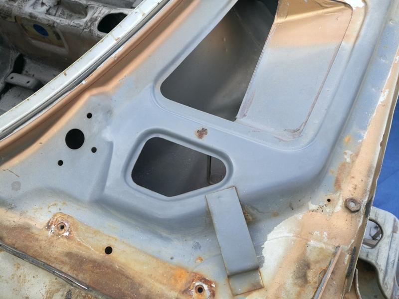 1 point