Leaderboard
-
conedodger
Free Member7Points12,513Posts -
Captain Obvious
Free Member6Points10,081Posts -
grannyknot
Free Member6Points5,158Posts -
JDMjunkies.ch
Free Member4Points637Posts


Popular Content
Showing content with the highest reputation on 05/05/2024 in all areas
-
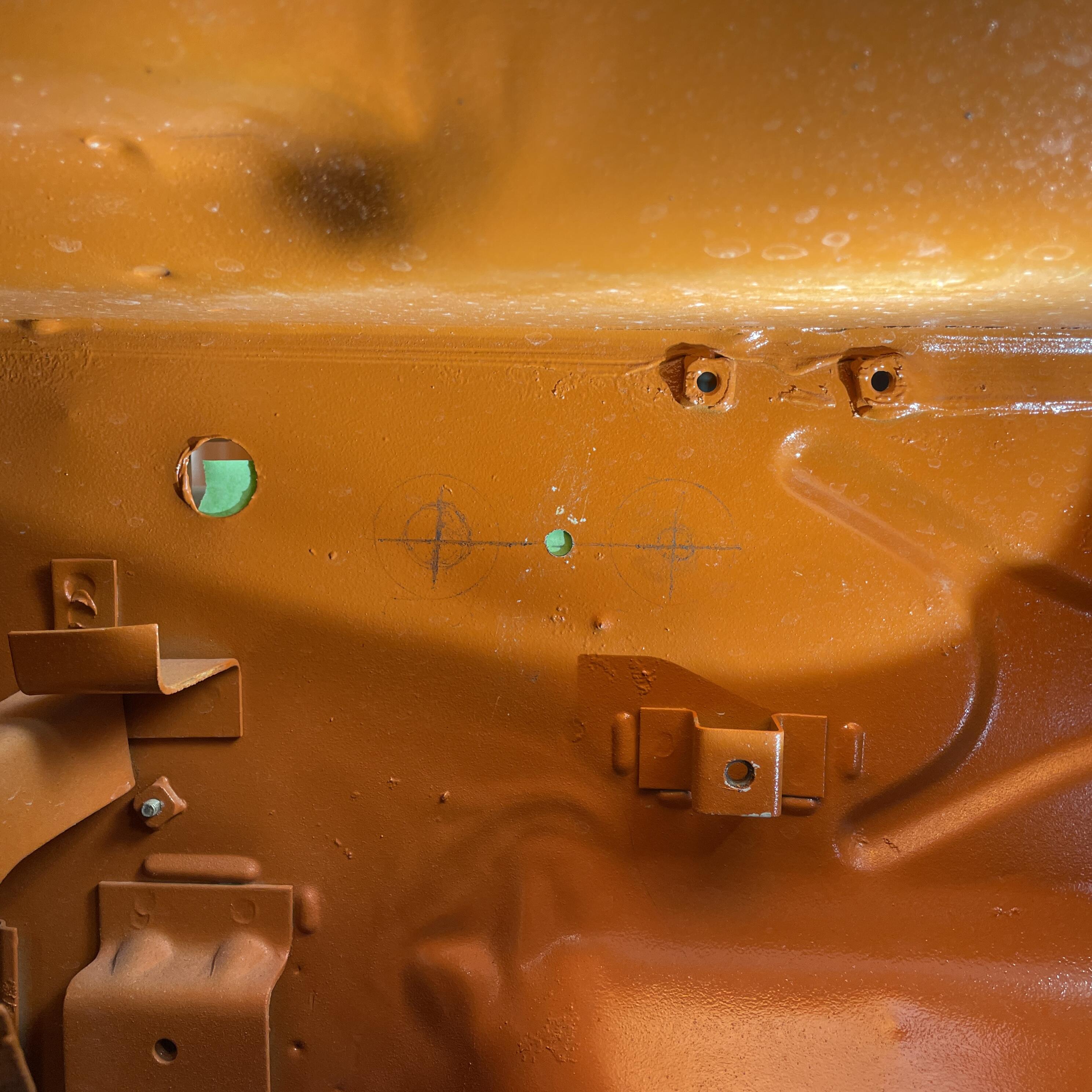
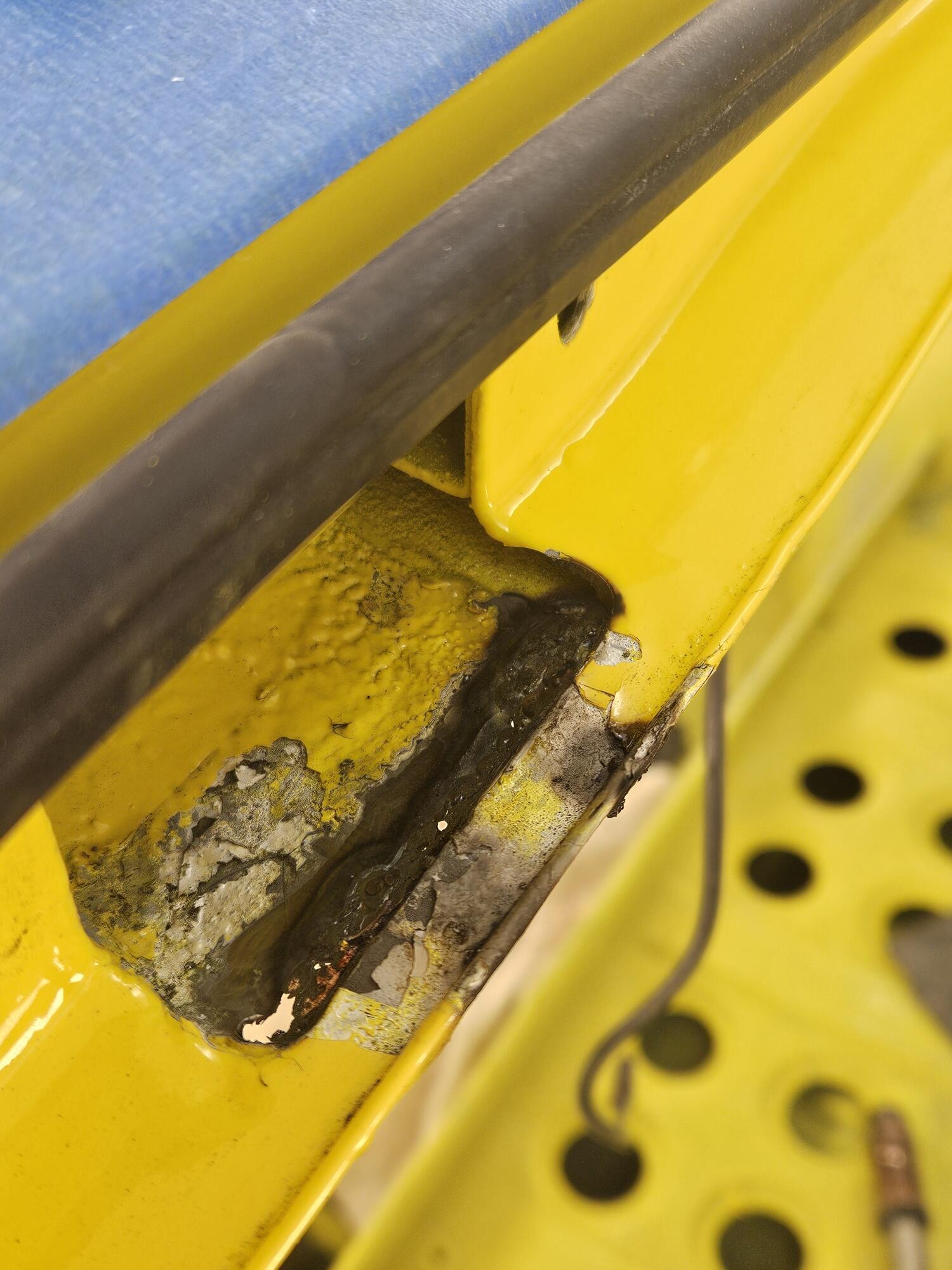
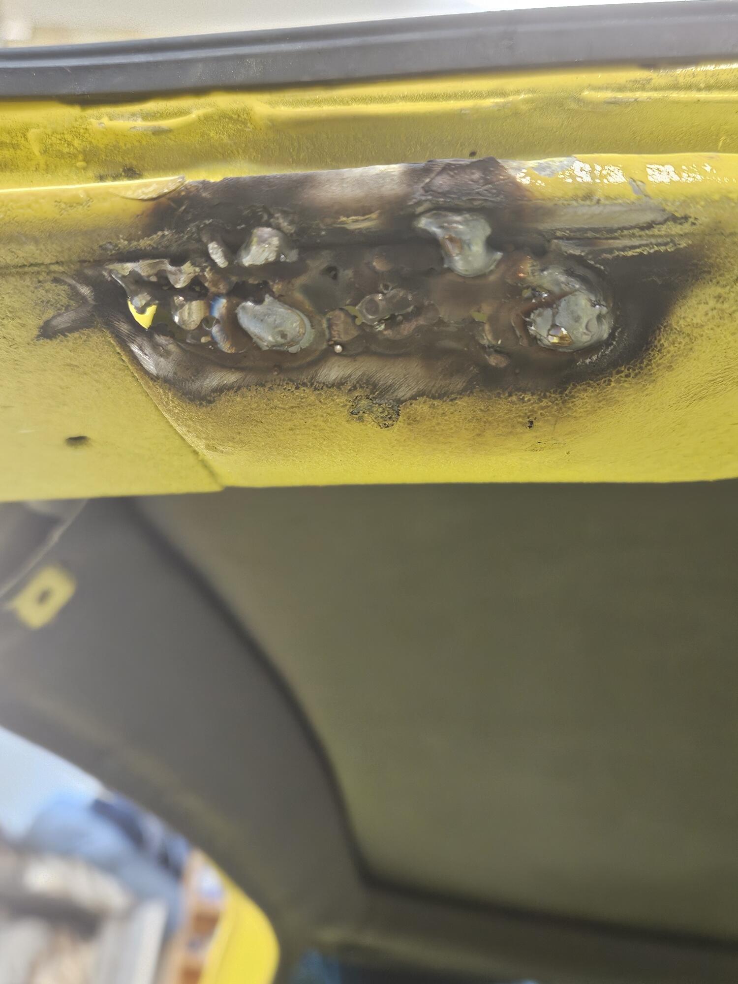
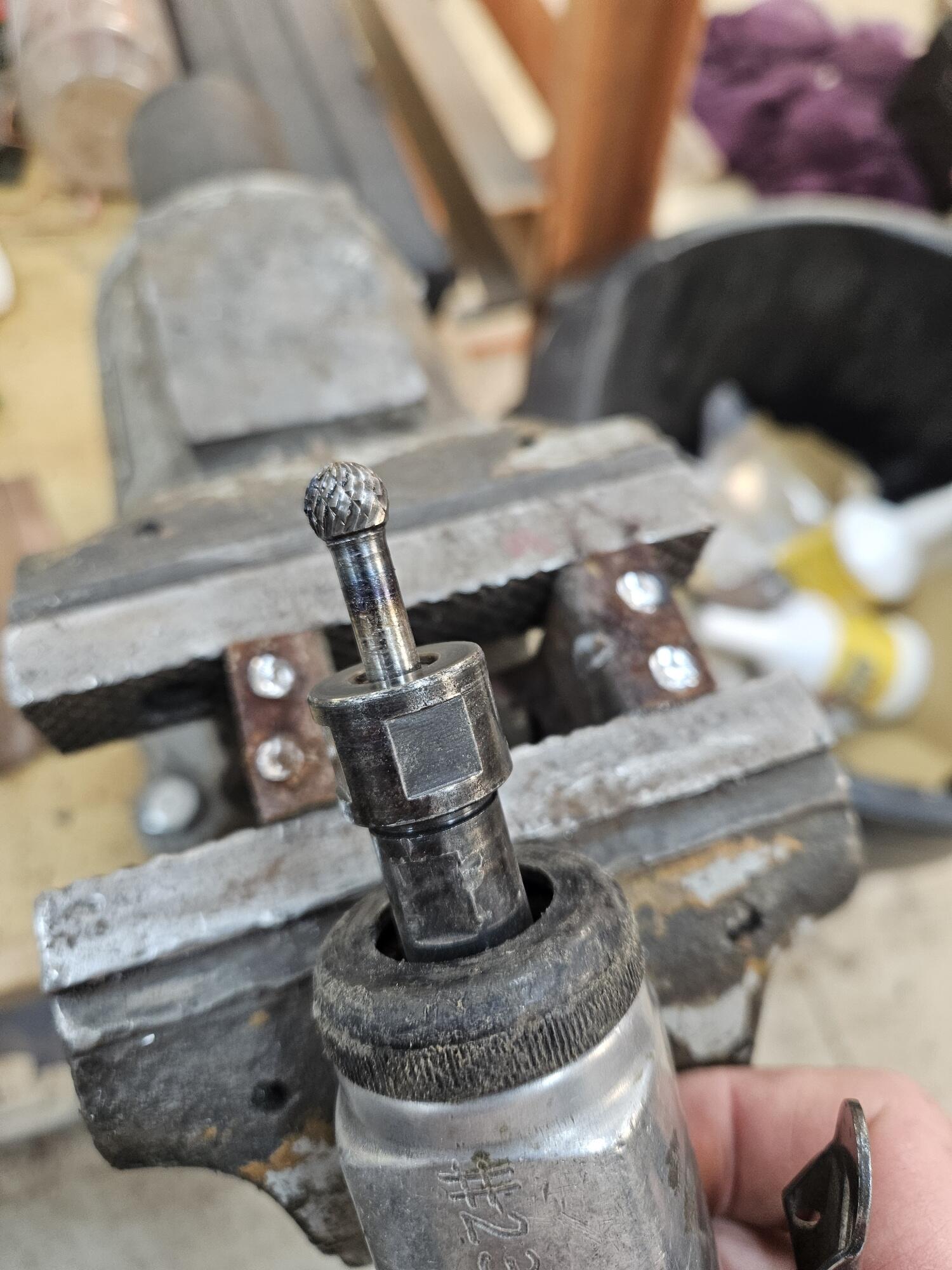
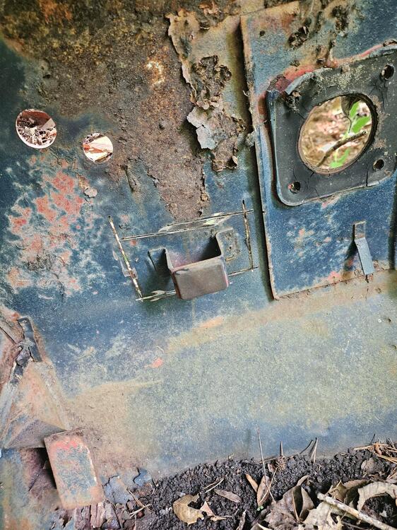
So now that the car is back at my shop. I thought i'd do a little inspection of all the details, to check if i see any need for rework in some areas. Overall i'm super happy. they did the best, especially since they have never seen a 240Z in their shop before my project. Some areas need a bit of work, and the first task of me will be to cover all the bare-metal spaces in rust-protection primer. They wanted to do it but when the trailer was available they weren't able to finish it, so instead they left me two cans of primer to do it myself. I'm happy if i don't have to pay them for something i can easily do myself. And considering it will be a few months in my workshop before going back for the final adjustment, it's a must to protect it against new corrosion. I don't want to describe every photo in detail, so here's just a gallery with random details. On this side the body line has been hammered back in already by the previous bodyshop: Optional footrest reinforcement, as on the japanese cars (that weld needs a bit of a cleanup, to satisfy my OCD). Luckily something i can easily correct) Floorpan reinforcement brackets on the rear, as on the original cars: That's it. I'm now in the mock-up phase of the car, where i have to prepare and test-fit everything and i'll show you some updates soon.4 points
-
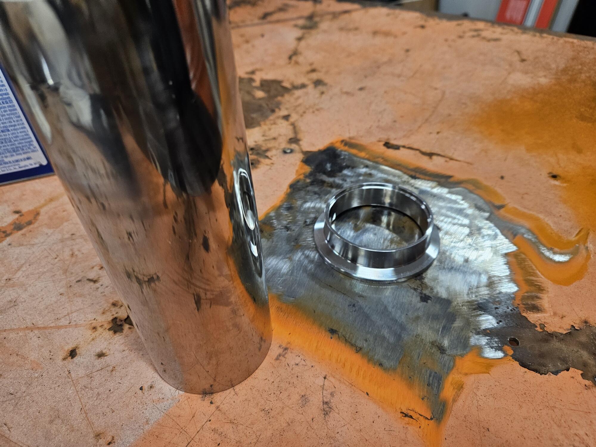
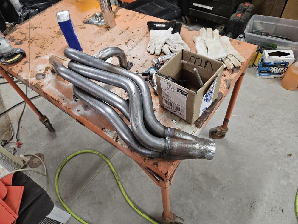
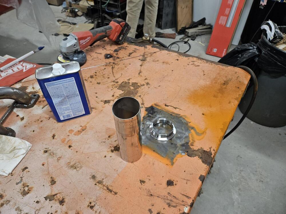
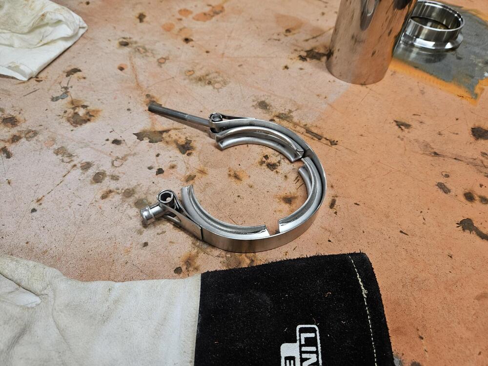
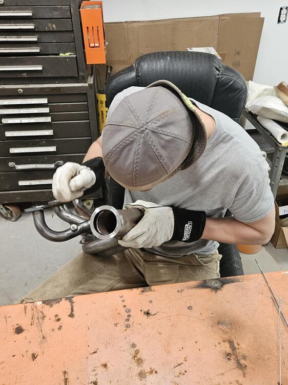
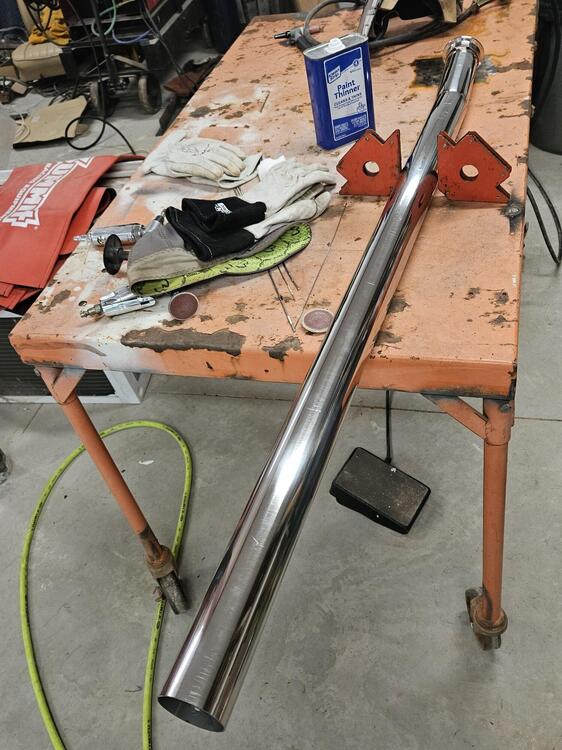
3 pointsSo yesterday Cody and I started building an exhaust for his car. We're running 2 1/2" stainless. No one really offers an exhaust for a 510 wagon Running V Bands at the end of the header. We got this much of the pipe built. I need to order a muffler now. The muffler is actually up under the back seat. It's not at the back of the car. The plan is to tack up the exhaust and then take it to someone else to TIG it all up

 3 points
 -
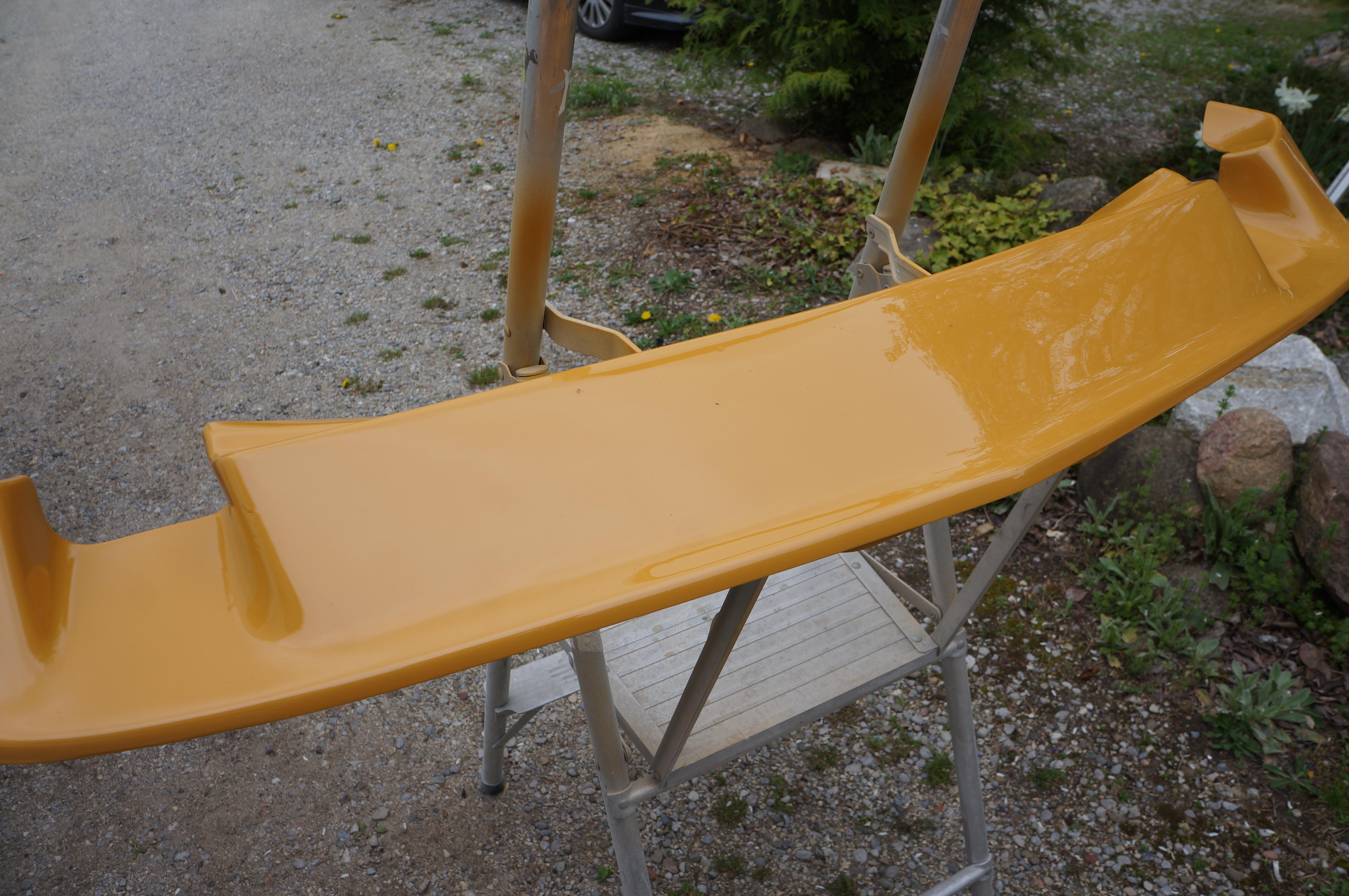
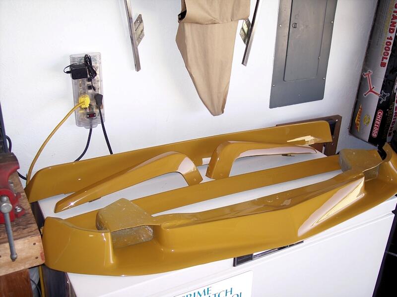
3 pointsI got the chin spoiler primed yesterday and colour and clear on today, I'll give it a couple of days to cure before installation.

 3 points
 -
3 pointsThere's no real reason to leave it up and in the way. It's just four bolts forward of the clamshell to remove and then push it down. Just as easy to raise it and bolt it back up when the dash is back in.3 points
-
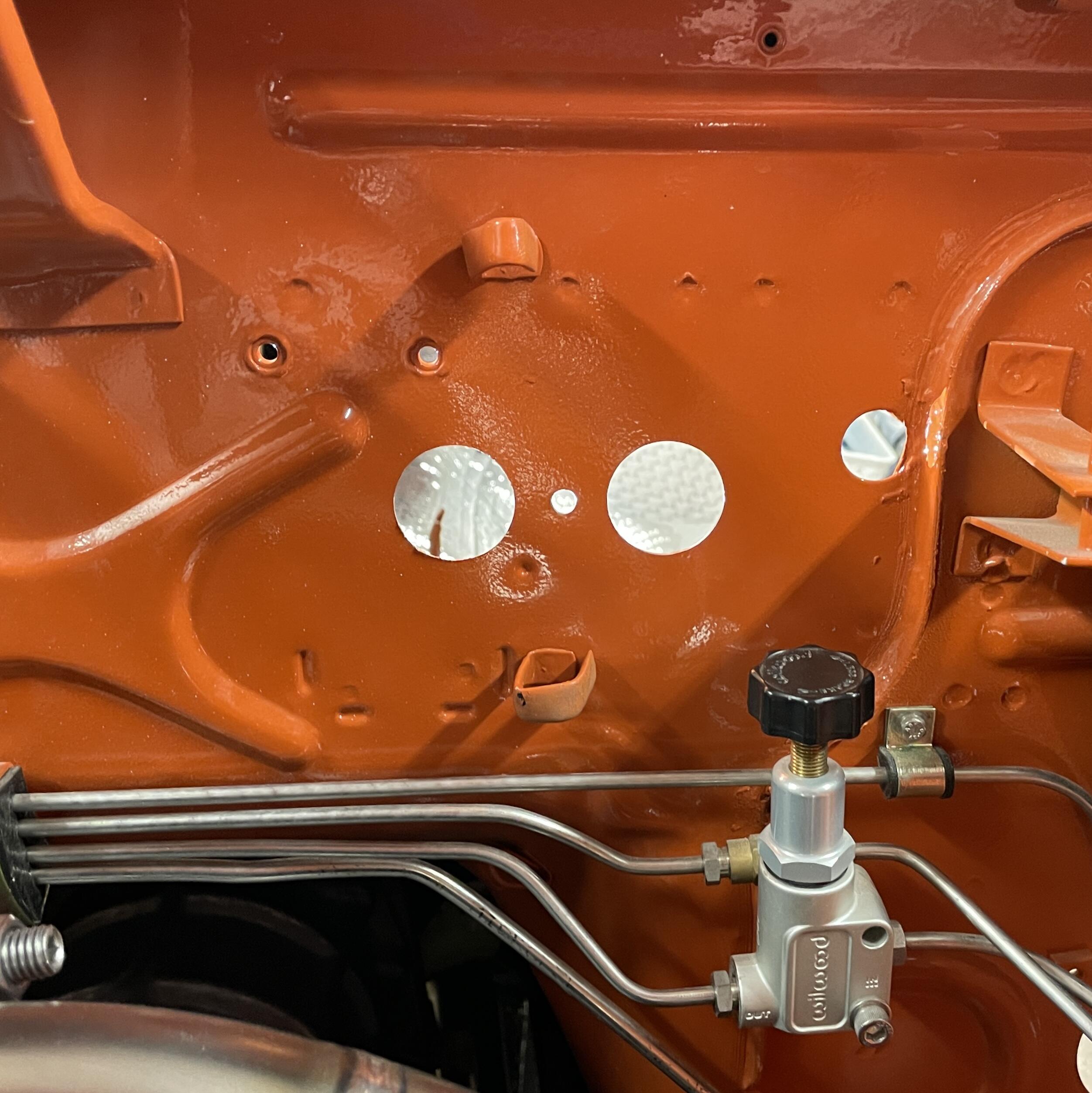
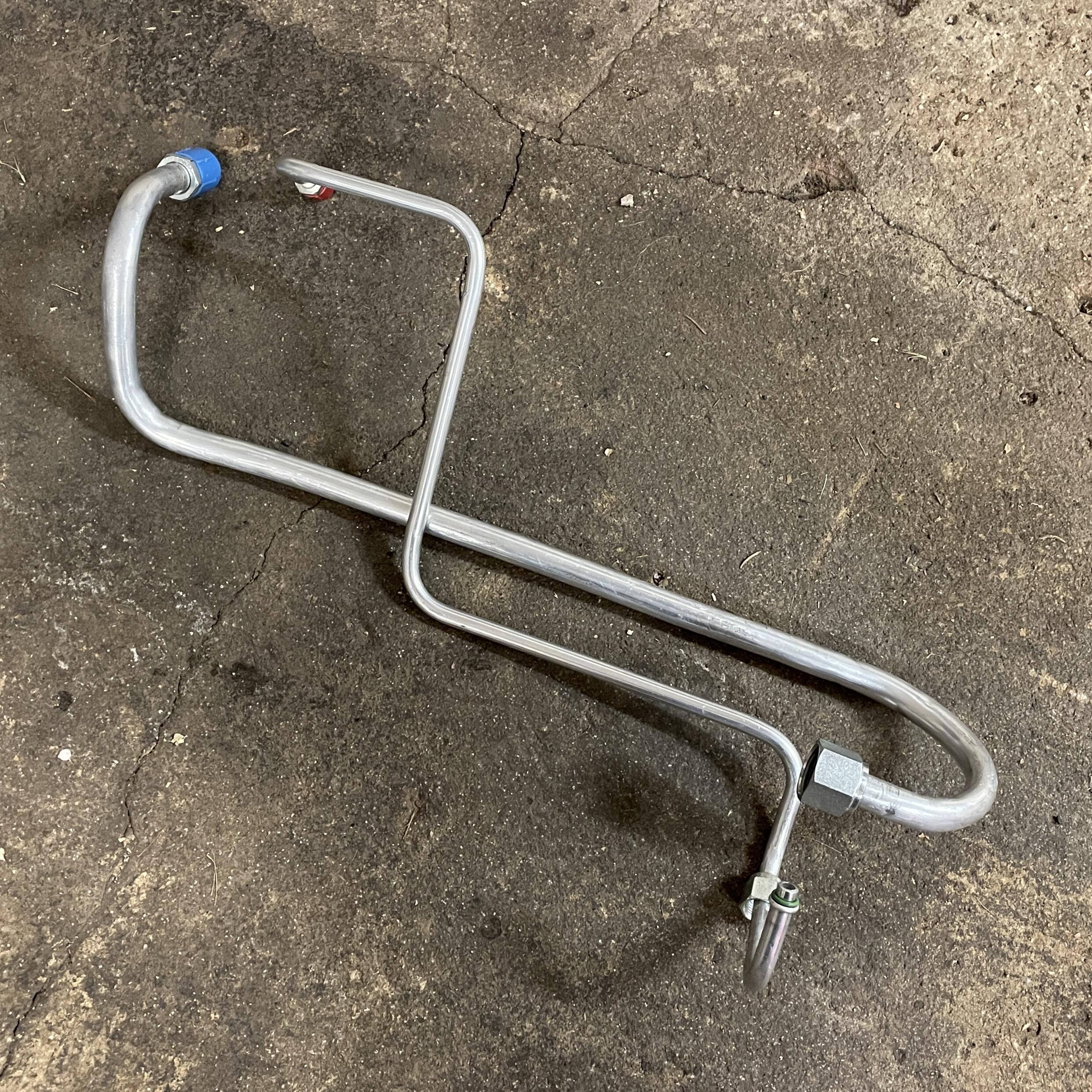
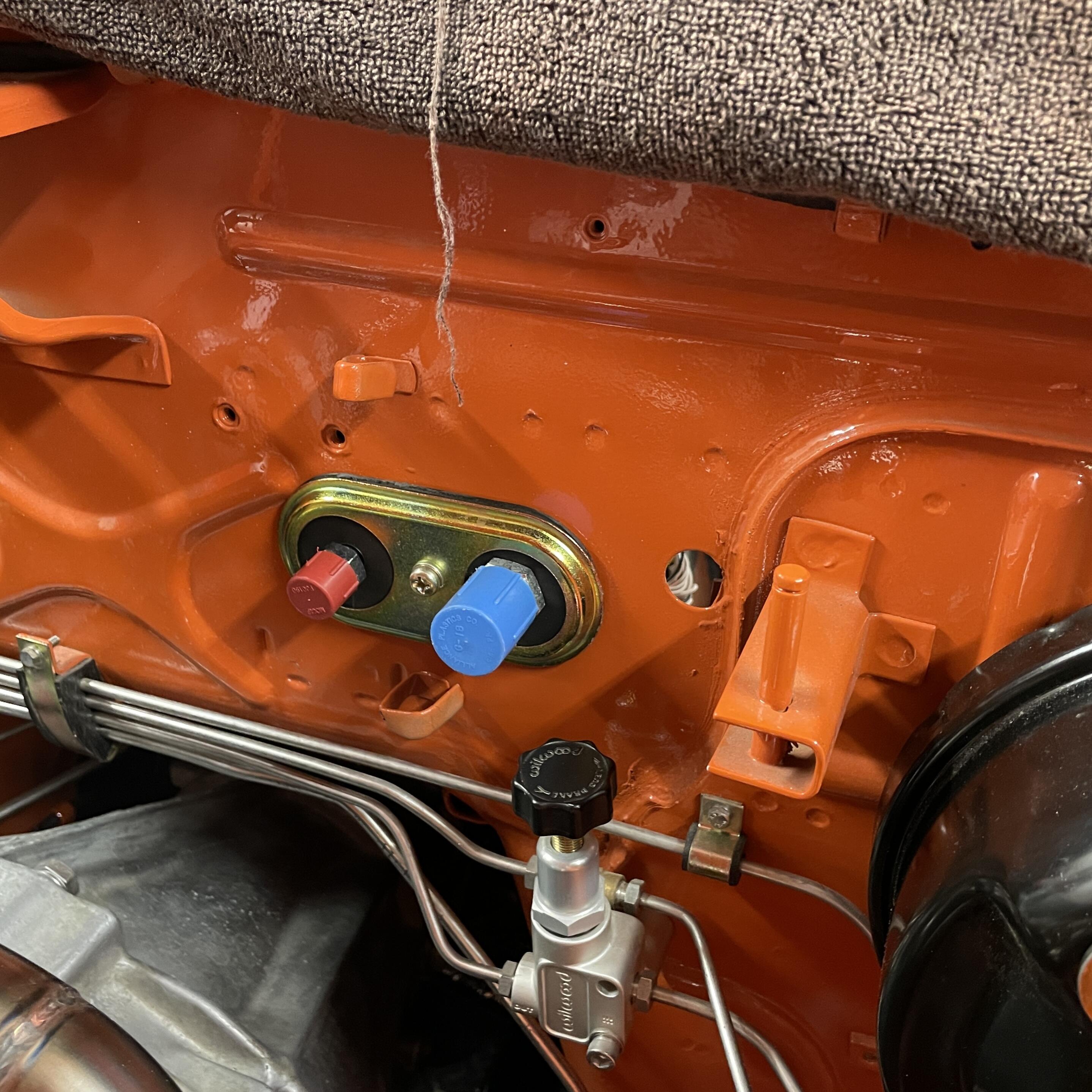
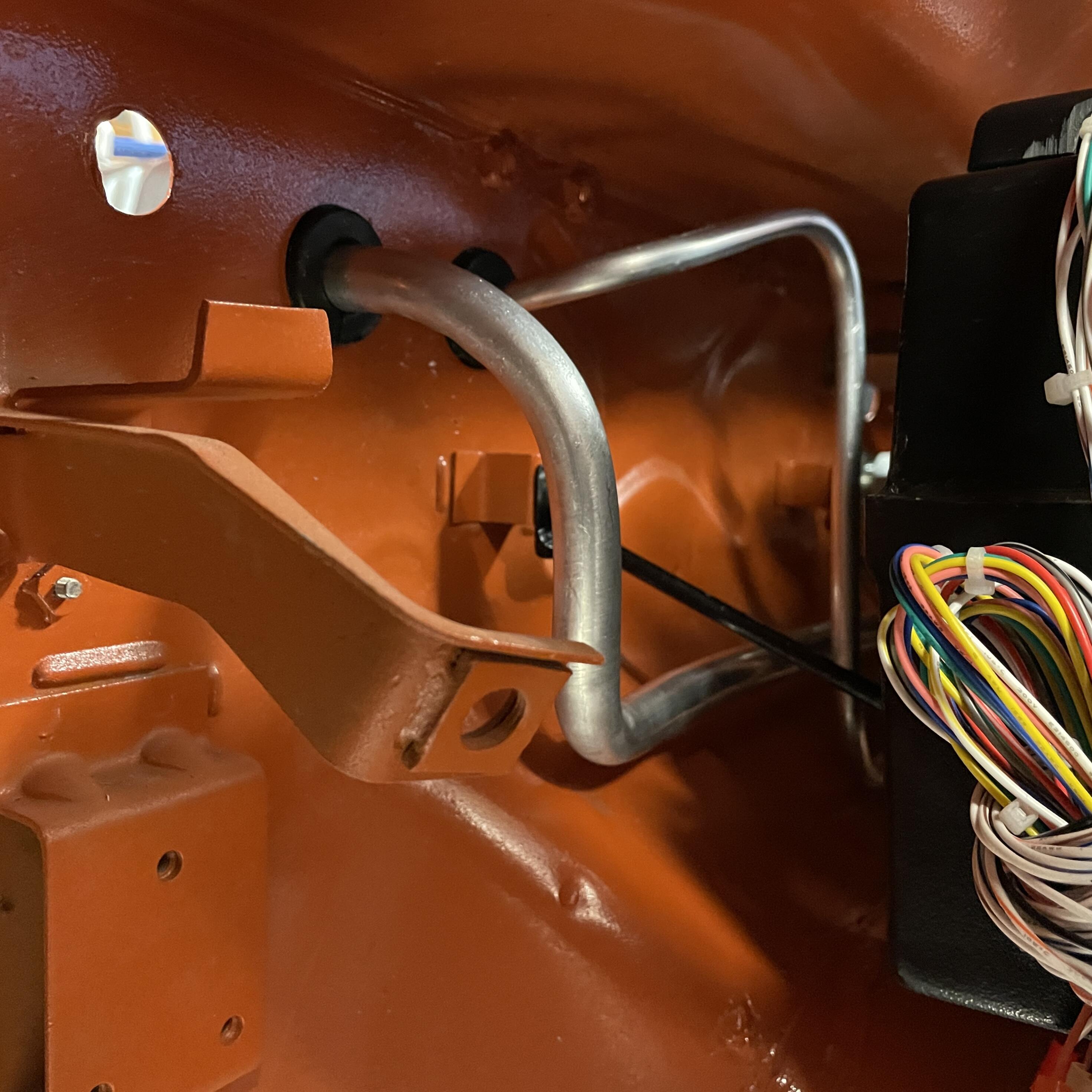
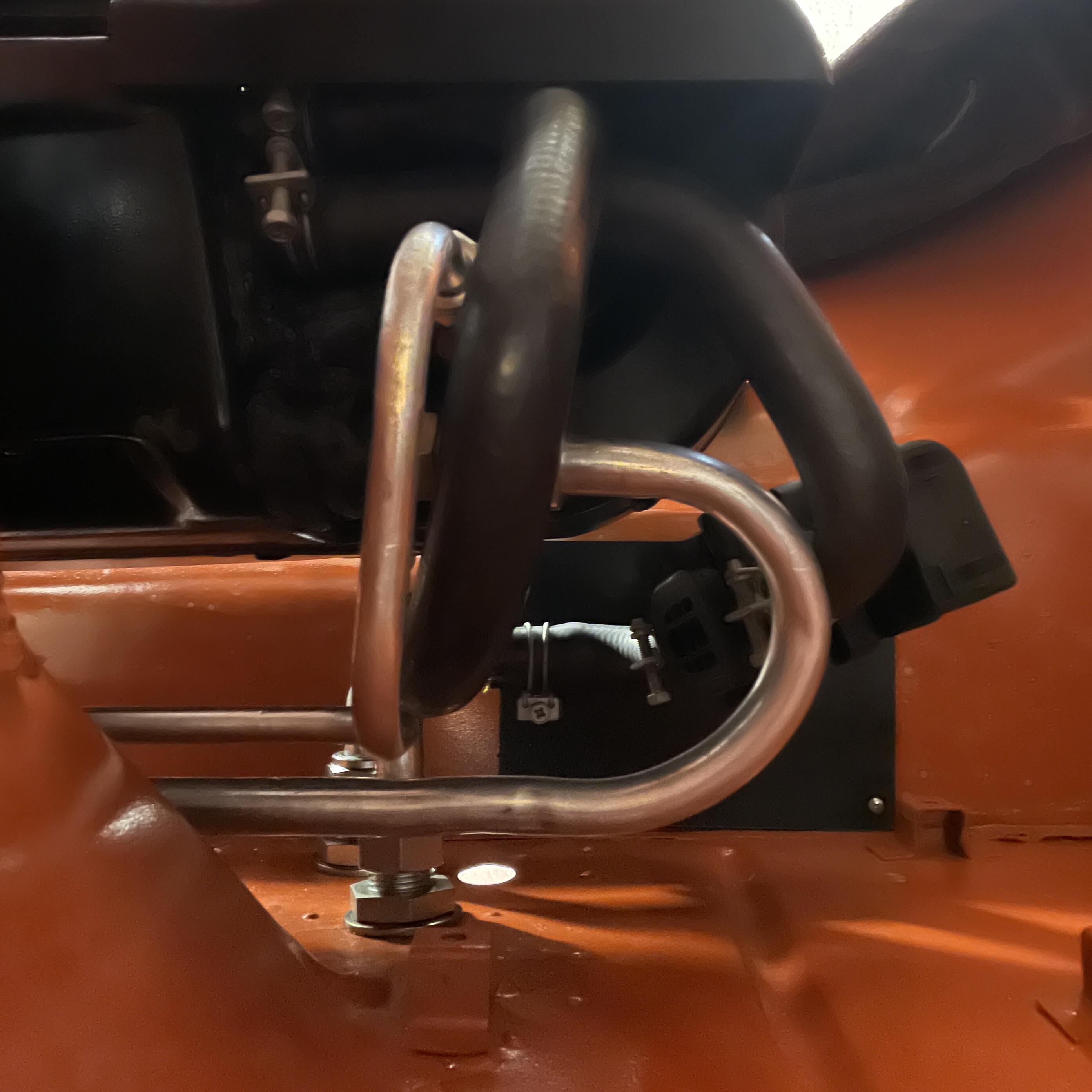
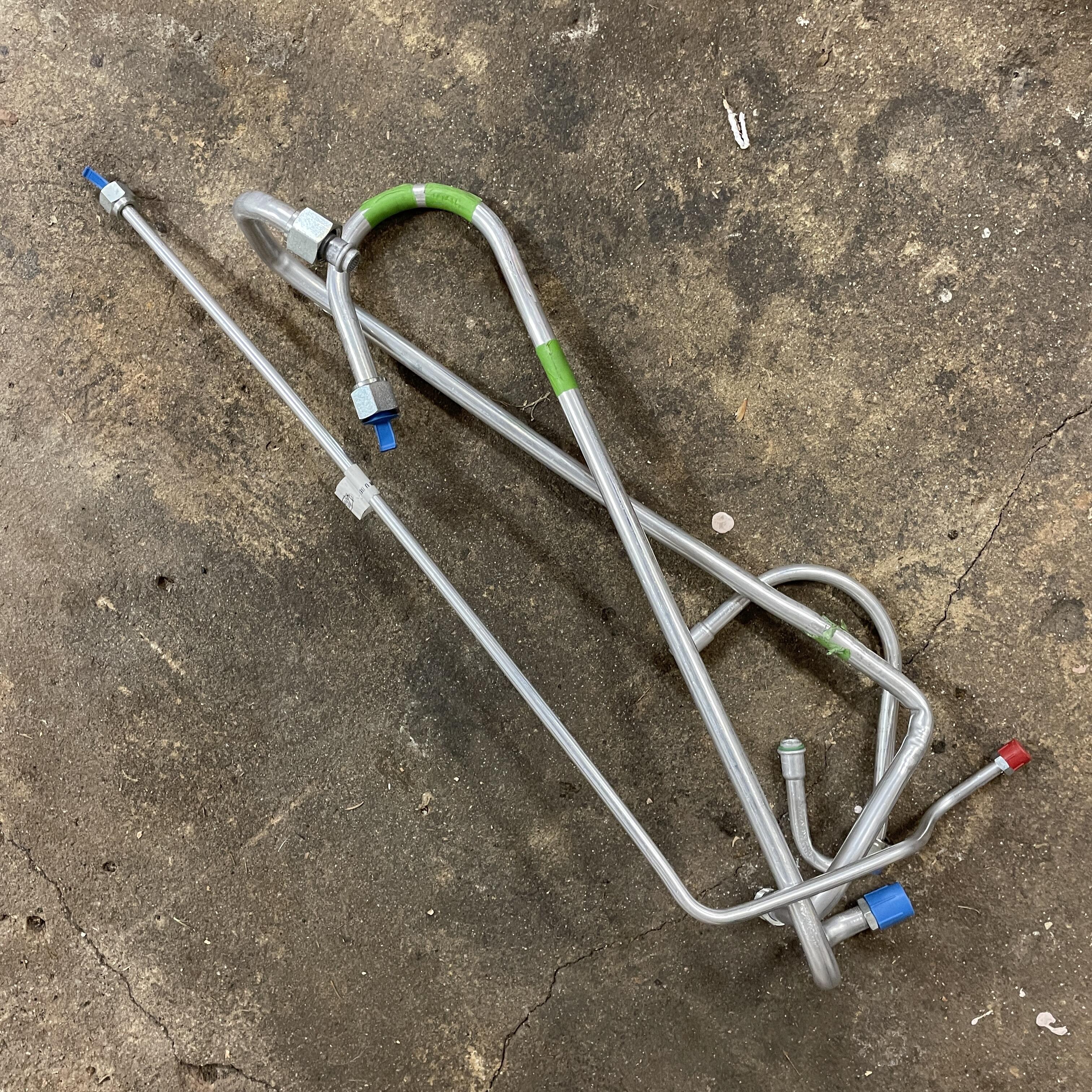
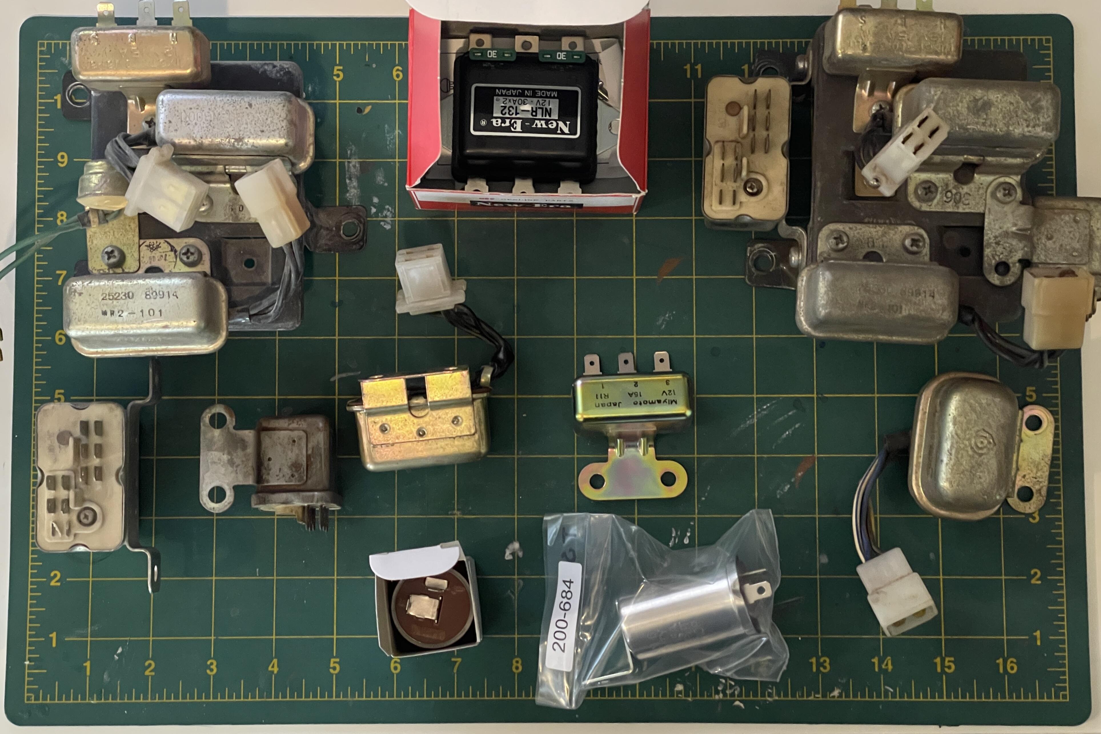
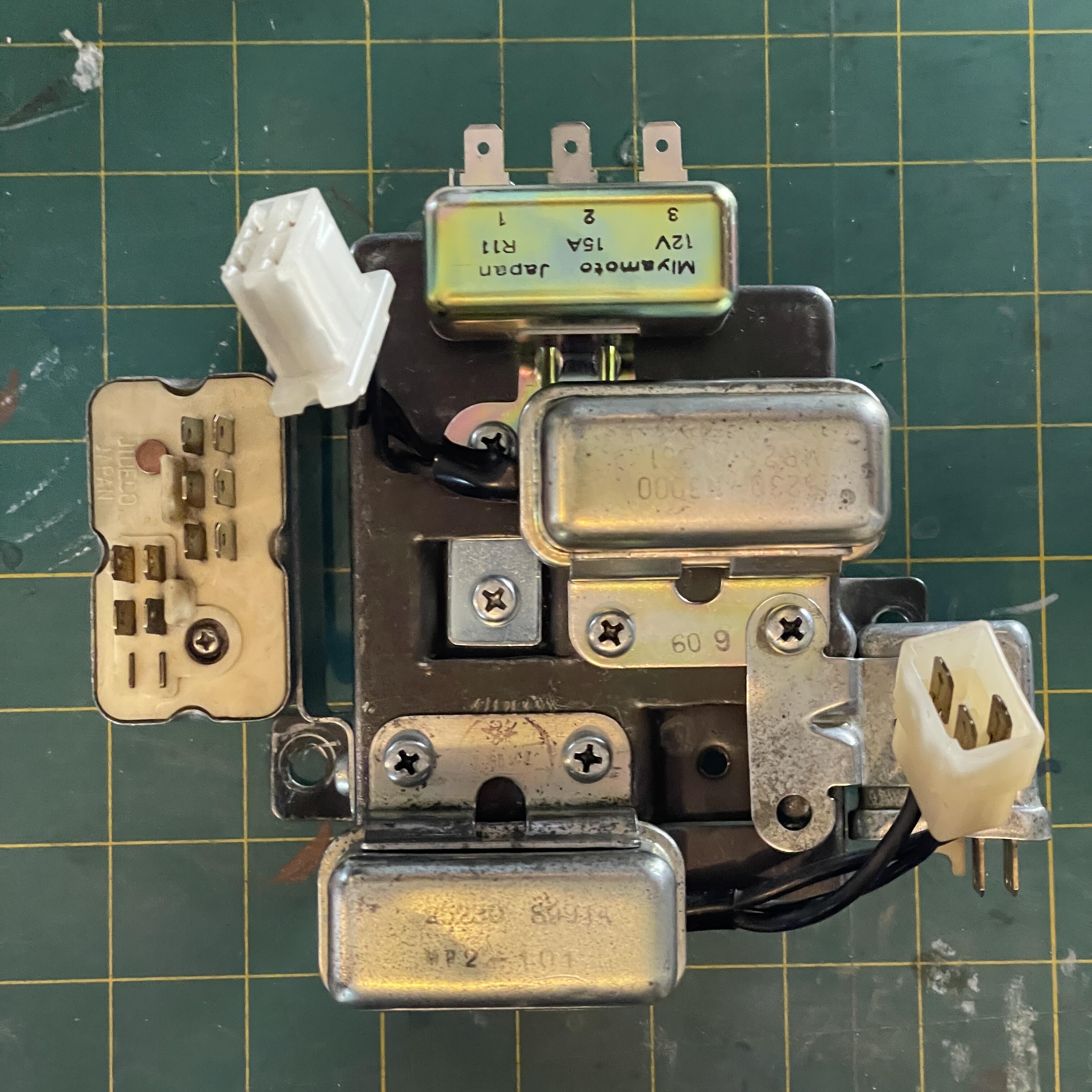
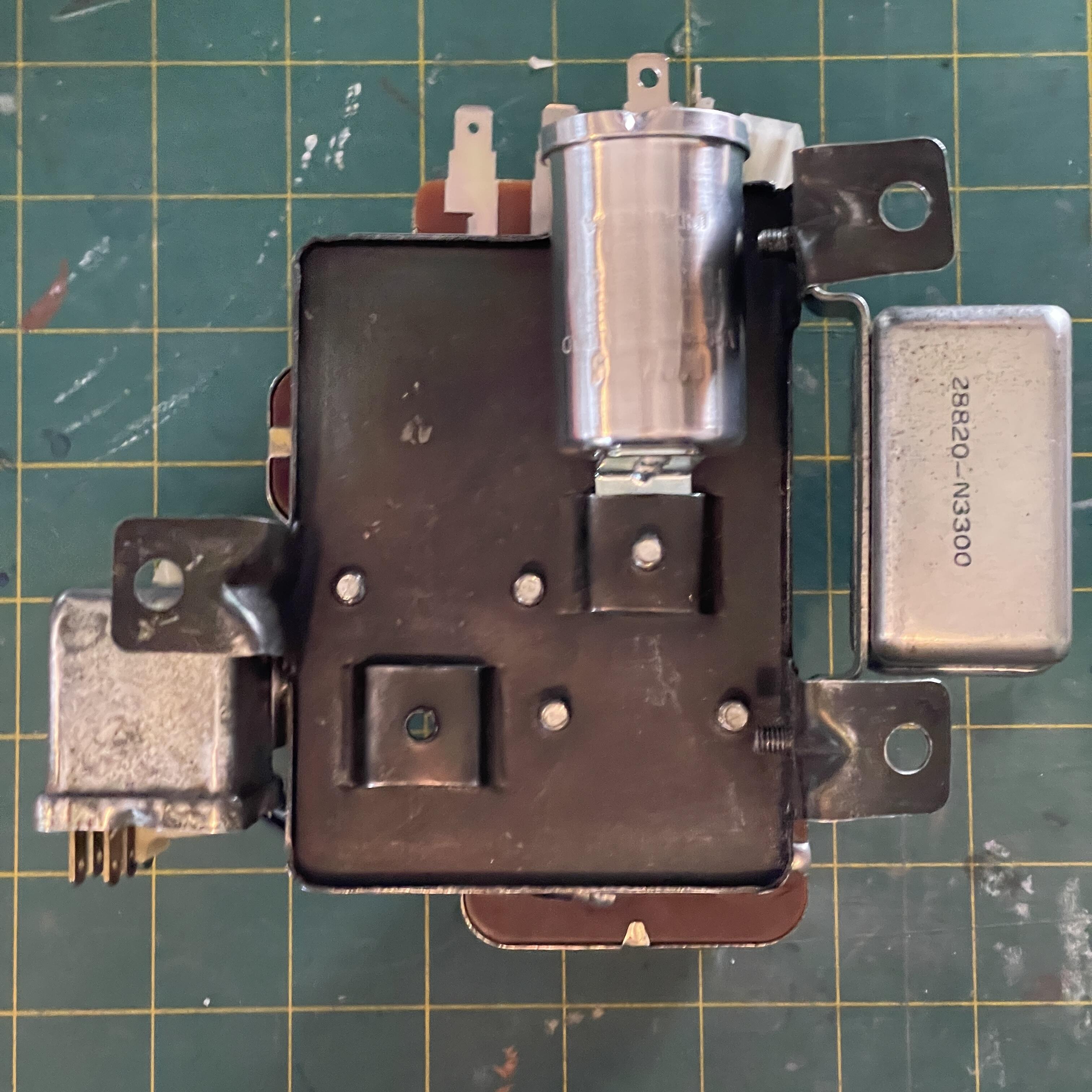
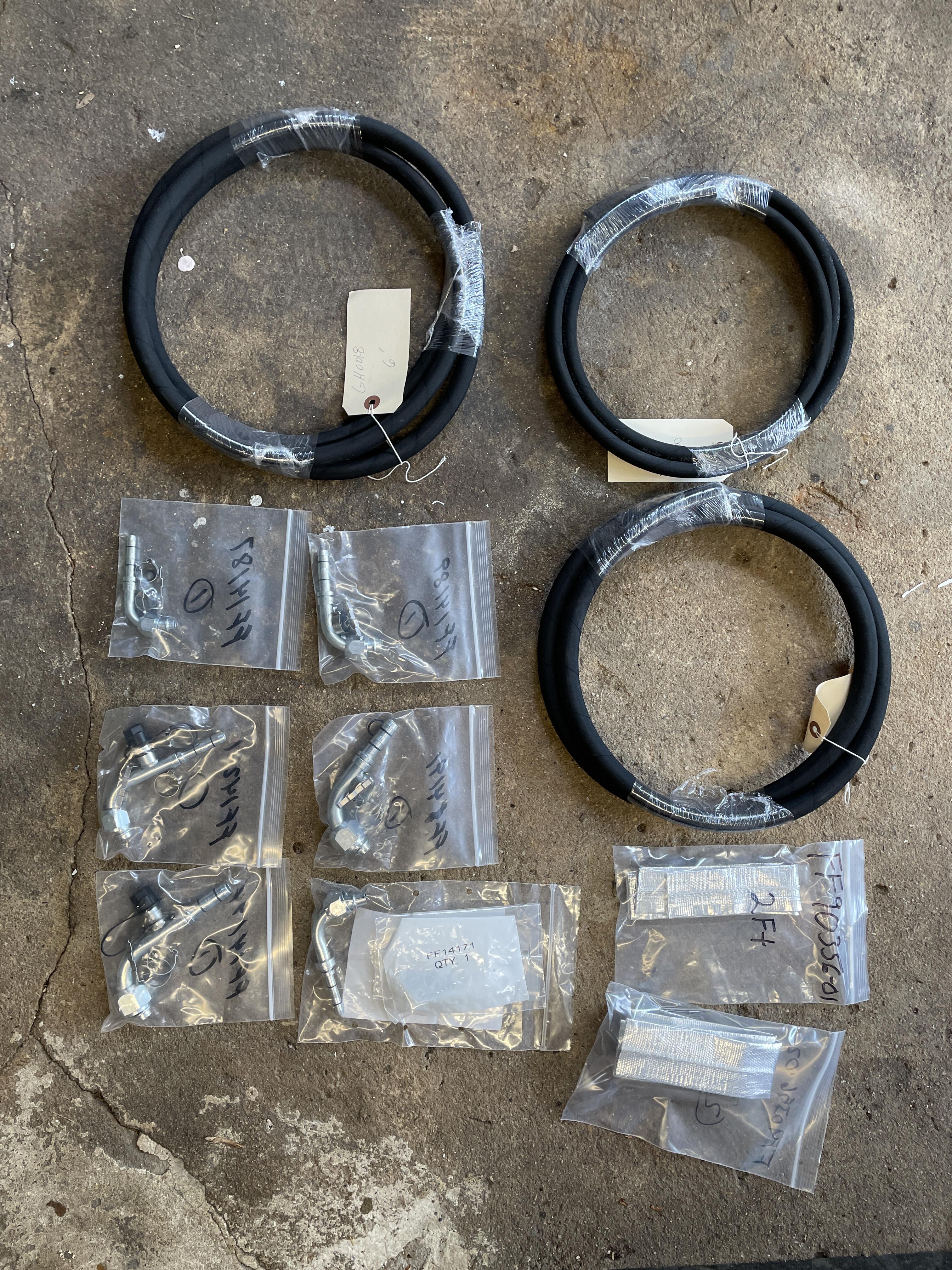
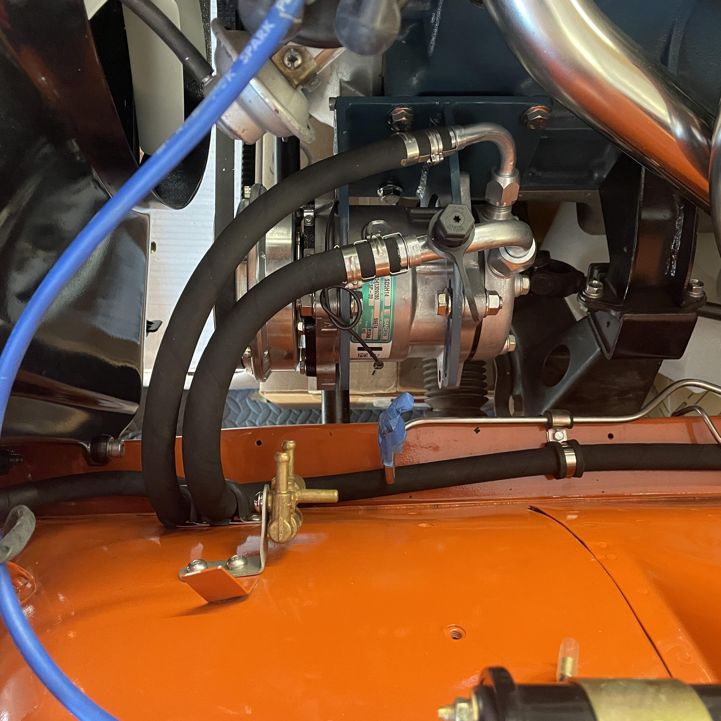
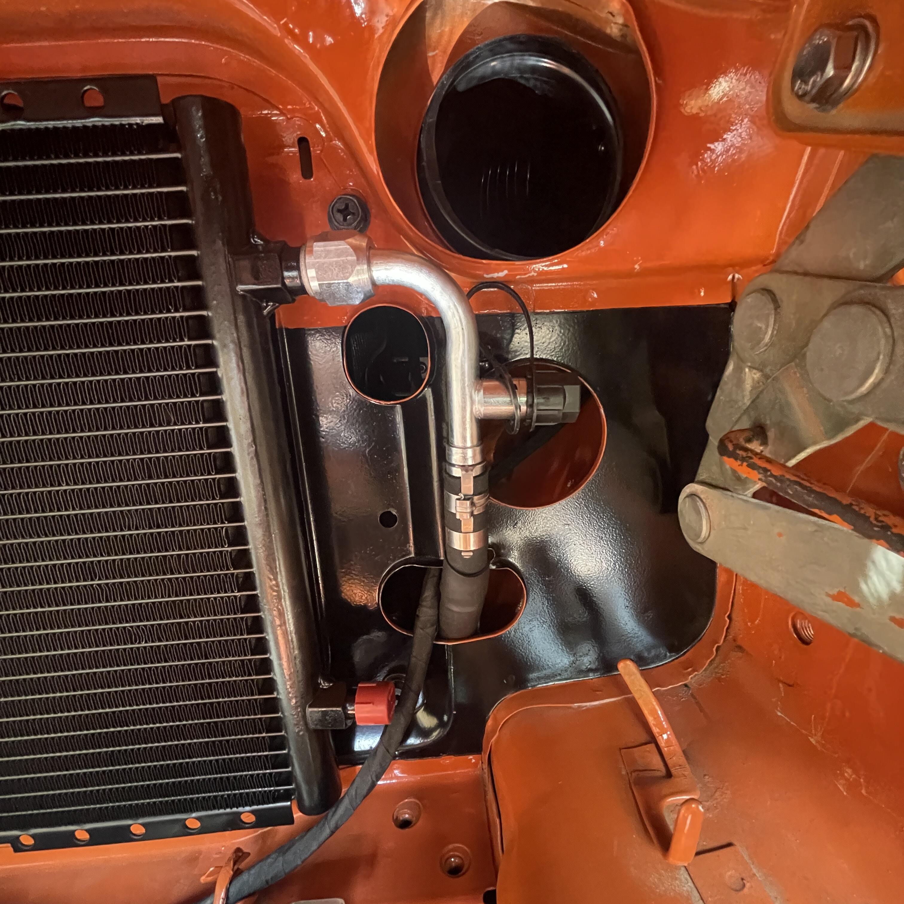
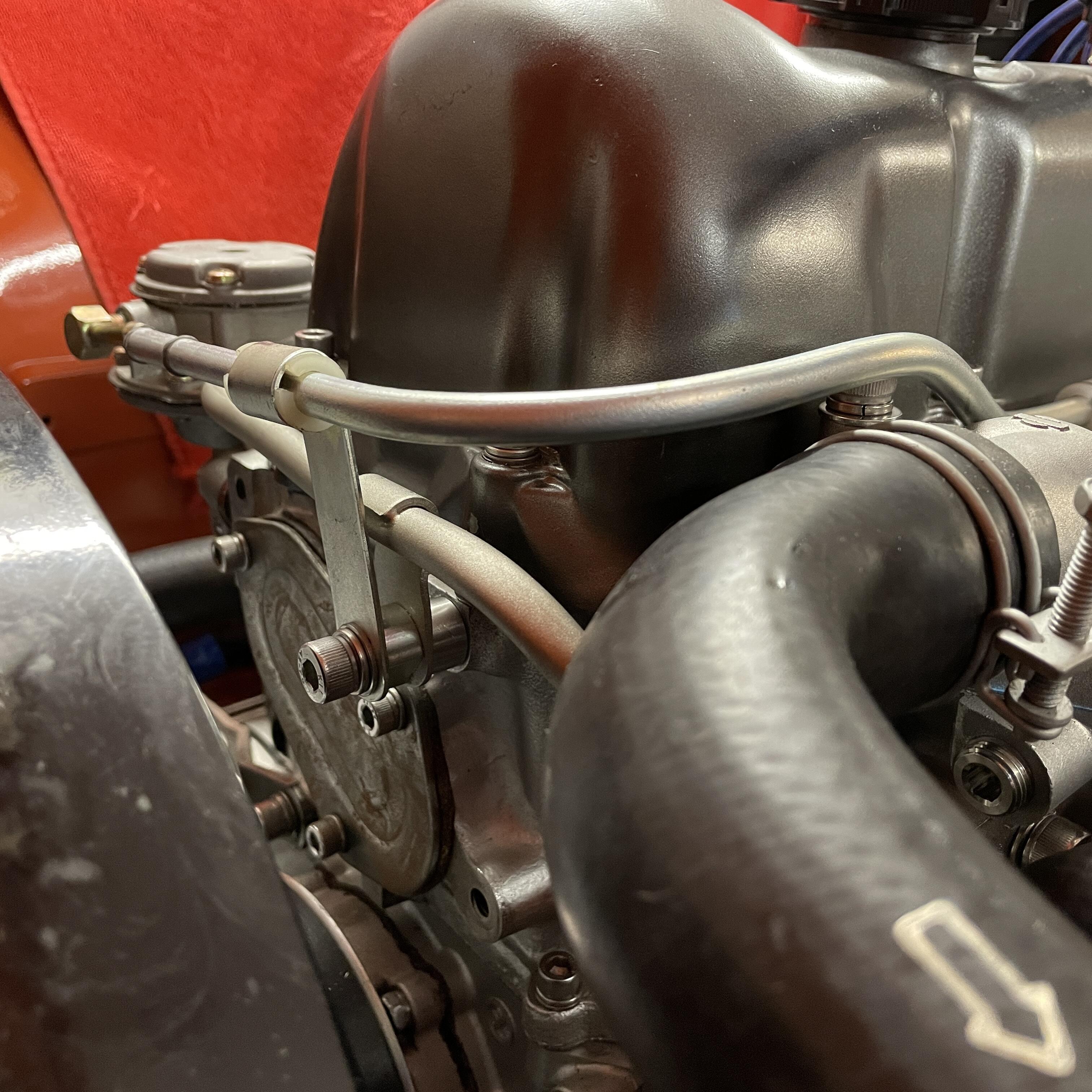
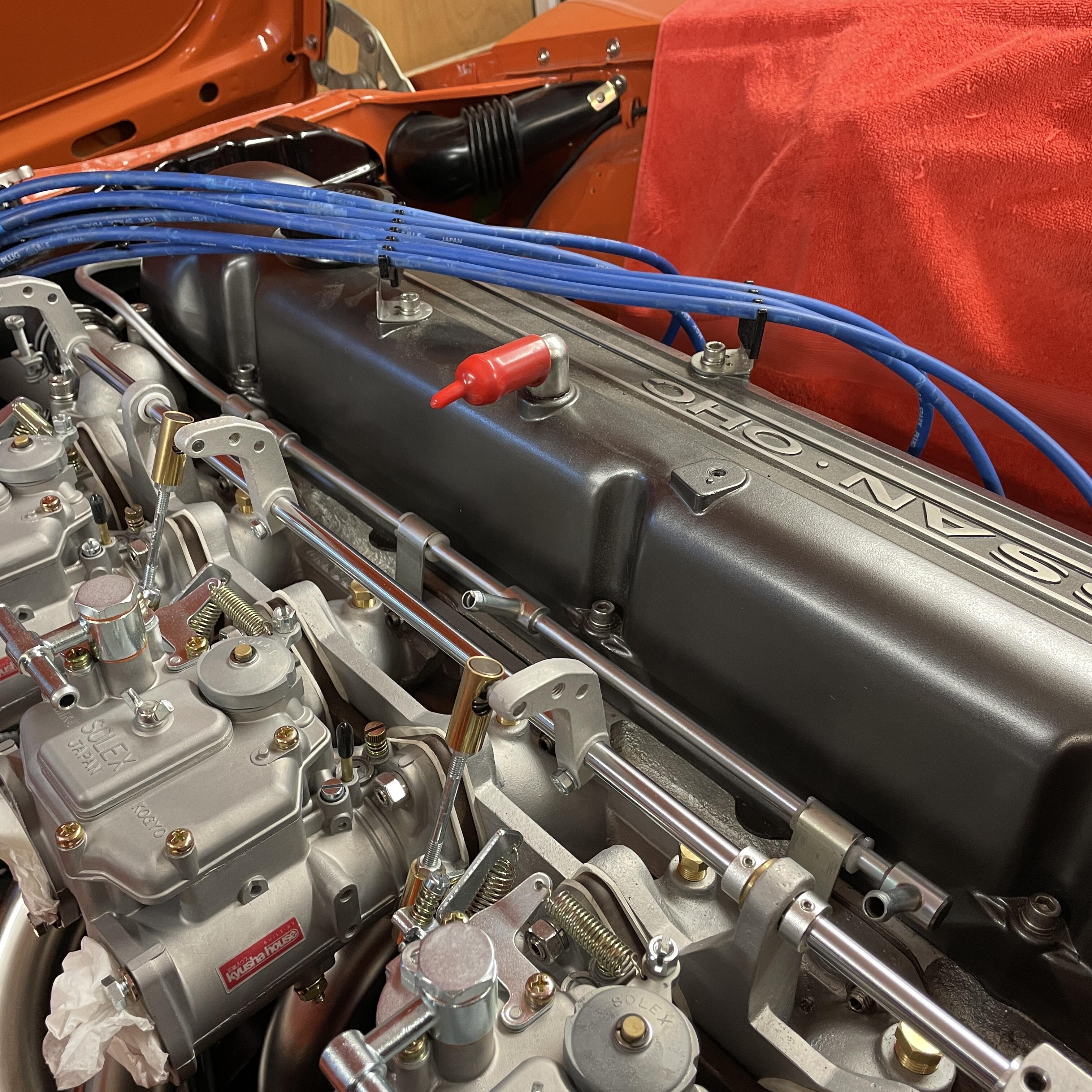
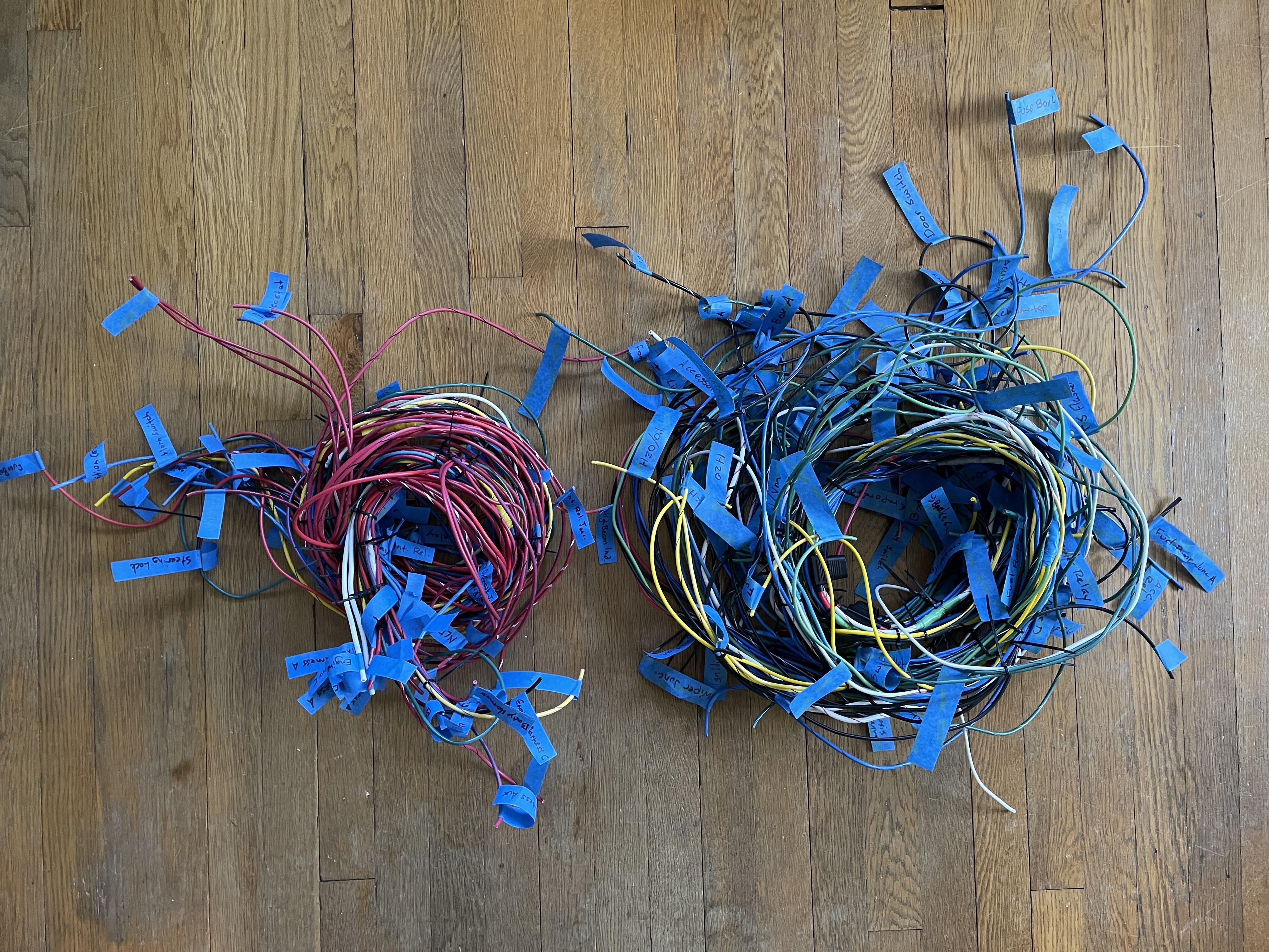
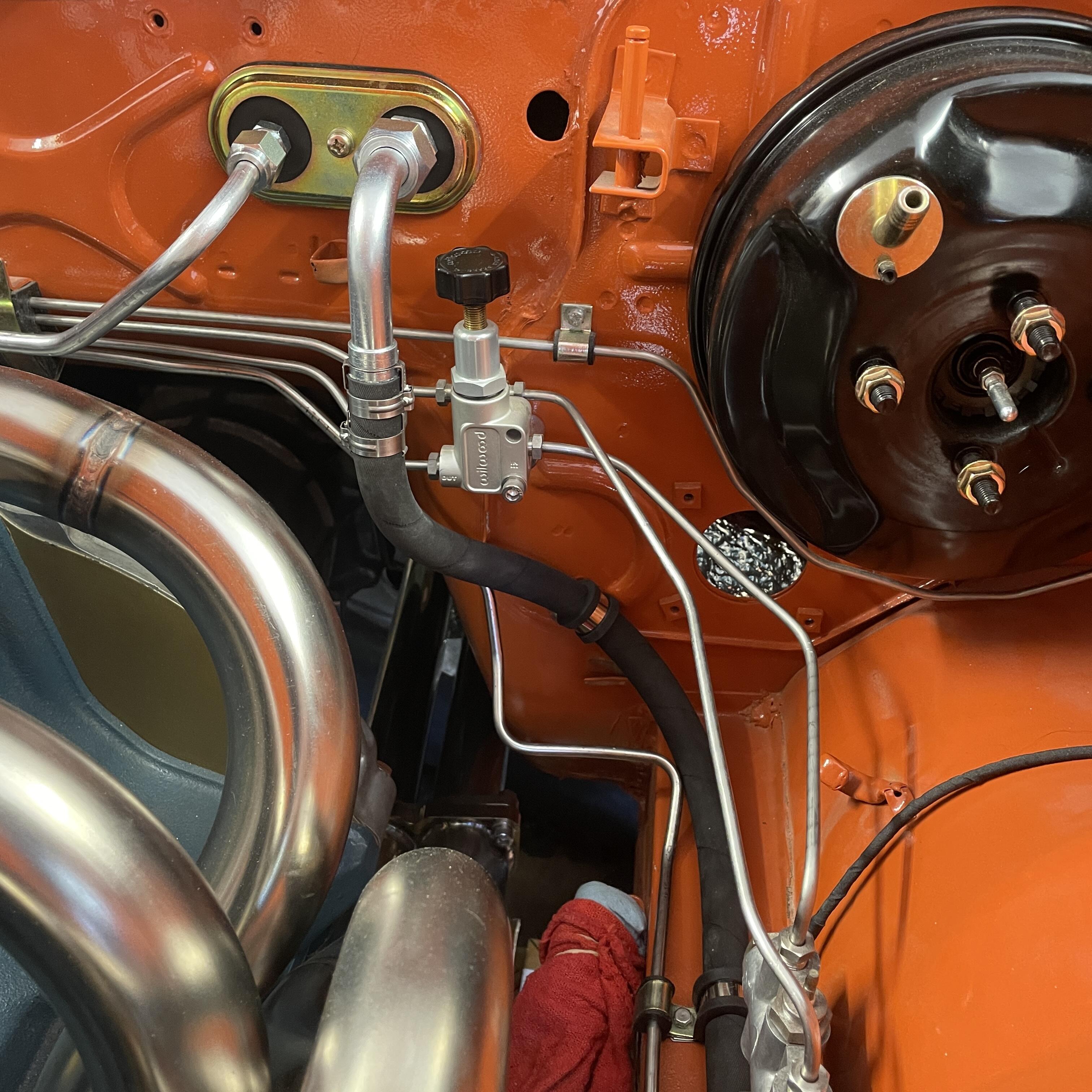
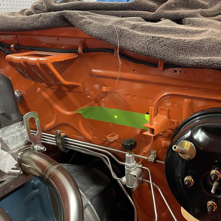
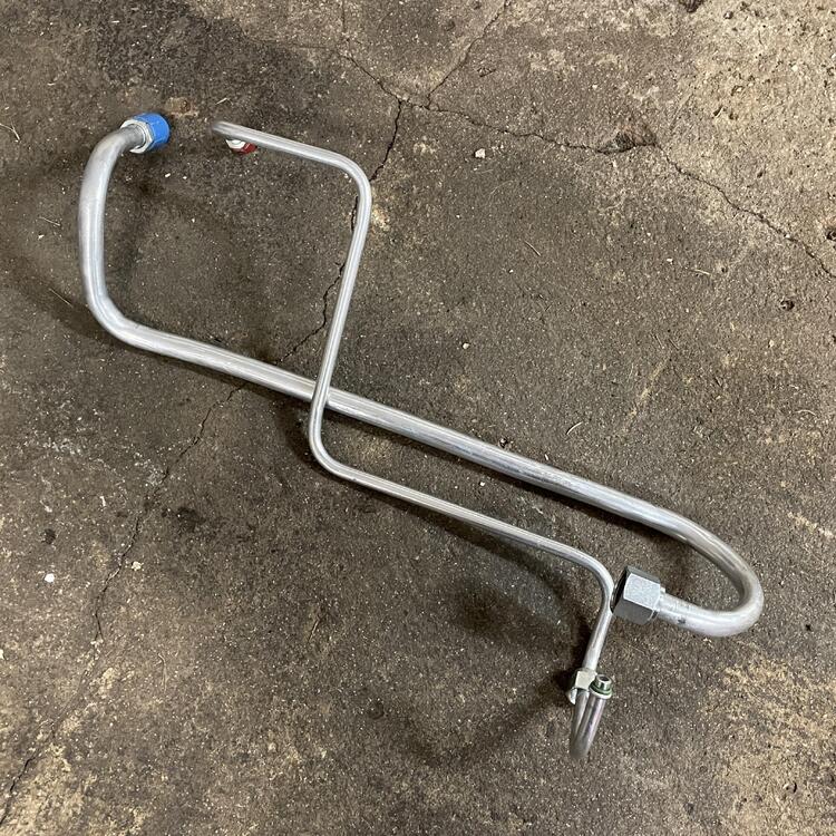
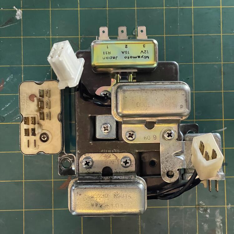
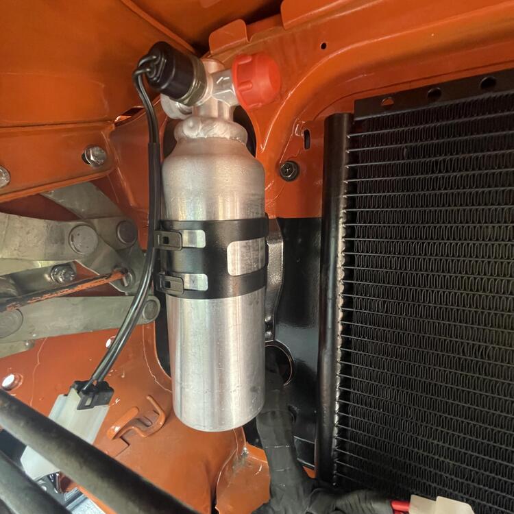
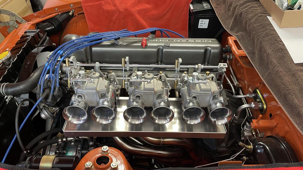
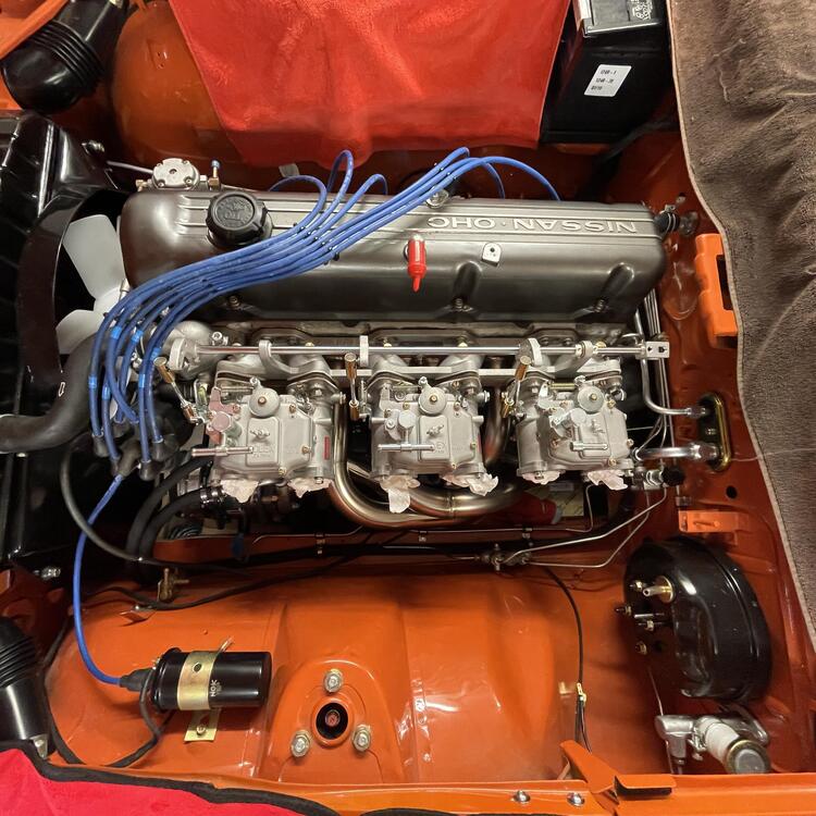
3 pointsOkay. Time for an update. I’ve done a bunch of random stuff, mostly on the dash wiring, but here and there with other stuff… First, I e been working on the AC lines. I went around and around in this one, looking into making stainless line, then buying the Godzilla kit, and then buying Vintage Air hard lines. I ended up settling on a mix of hardlines and Aeroquip E-Z Clip hoses. ”Prototypes (i.e. failed attempts): AC hard lines for inside the cabin are in, but ugly. This one was a pain. I went through several pieces until I got the lengths and bends right, and even these aren’t wonderful, so I’ll redo them one more time. I opted for Vintage Air U-Bend-Em aluminum hard lines because stainless was going to be far too expensive and the hose options I investigated didn’t quite cut it. These fit okay, but you can see the -06 line is too long and I had to cram it in. I got another so I could make them fit better. It’s important because right now they are pulling on the lines they connect to in the engine bay. The firewall insulator is OEM from eBay. It’s in pretty good shape considering its age. • • • I’ve also been scrounging up my relays, which I talk about in my wiring thread. The fun one to find was the seatbelt warning buzzer and the three wire door switch, but I was able to find them after a lot of direct messaging. I’m not 100% certain all of these relays are good (still testing), but I cleaned up the best looking pieces from my pile and assembled them a few weeks ago. • • • The wires for the dash harnesses are all cut, spliced, and zip tied, so the next step is test fitting them in the dashboard and marking where they will get cut for the terminals. I won’t be wrapping these until I know everything works, so that’s a ways off. They look like a mess here, but they’re simpler than they could have been. They’re pretty heavily modified, with the stereo and antenna deleted and add provisions for various new components like footwell lights and USB-C plugs. All of the splicing and positioning has been checked and verified against the diagram I made as well as the original harnesses. The wire is heavier gauge and marine insulation (yes, overkill). Will it fit? We will find out. Why? Burnt wires, the PO used a harness for an automatic in a manual car, I wanted to incorporate the fuel harnesses into the dash harness, and to make it fresh. That right there is over a year in the making. Glad it’s over. • • • Now on to the engine bay. Carb-side AC lines are done! The hose for the other side is in the mail, so I’ll knock that out soon. You can see the prototype of the hard line in the photo above. There are two problems with it: the max length is 72 inches, which is about two inches too short to get a nice clean routing, and about six inches too short to tuck it away and make it discreet; and the end is just slightly wrong for the R32 Skyline AC drier/receiver in the last photo in this sequence. I like that drier too much to switch it out and I’m uneasy about modifying the end of the line and potentially not getting a tight seal, so hoses it is! The hose for the E-Z Clip system bends tighter than regular AC hose, but it doesn’t bend quite as tightly as I had hoped (it’s rated at a 2” radius for the -08 hose) so it gets weird in a couple of places, and I’m still unsure if these Danfoss E-Z Clip fittings are going to be air tight. We will find out when I try to charge the system. You can barely make out where I sleeved the hose at points where it might rub on something. I used three layers of heavy duty shrink wrap for this and I think it looks almost like it’s supposed to be there. All I need to do with these, though, is add a hose separator that is the right size to keep that -08 hose from flexing too much. I have two of them in the mail to me now. • • • I installed the fuel rail for the triples the other day. This was surprisingly involved. I thought I would just slap it on and call it done, but there were several barriers; nothing crazy, but time consuming and requiring thinking it through. I had intended to use the empty M10x1.0 holes that are next to the M8 manifold mounting holes, but the rail brackets aren’t drilled for that, and the manifold nuts are too close. I tried a bunch of different workarounds but in the end it was easier to use the manifold studs as the mounting points. To do that I had to use longer studs, which meant grinding some relief into the manifold. I REALLY didn’t want to do that, but I caved and broke out the Dremel tool. Was I paranoid I was going to pierce the runners? 100% But I didn’t. I switched to hand files after a while just to make sure I wasn’t going through it too fast. All those years of model making have paid off in writes on this car. So once that was done I put the thing together and realized these rails are meant to go with electric fuel pumps. I have a NOS mechanical pump on this car and I worked too damned hard to find it to go dumping it for this, so the rail got a trim and beads rolled on the end. Looks like it’s supposed to be like that now. After that I just had to tweak the bends to make sure it cleared everything and it’s good to go. Now to figure out the fuel hoses and find a fuel filter bracket. • • • So the big question now is… HOW TO ROUTE THE FUEL LINES? I would like to use the return line, so I would need to send the fuel back to the other side somehow. Right now I am leaning toward installing my Mikuni cooling bodies and running a line across the front of the engine under the coolant line, but I’m trying to think of something more elegant.


 3 points
 -
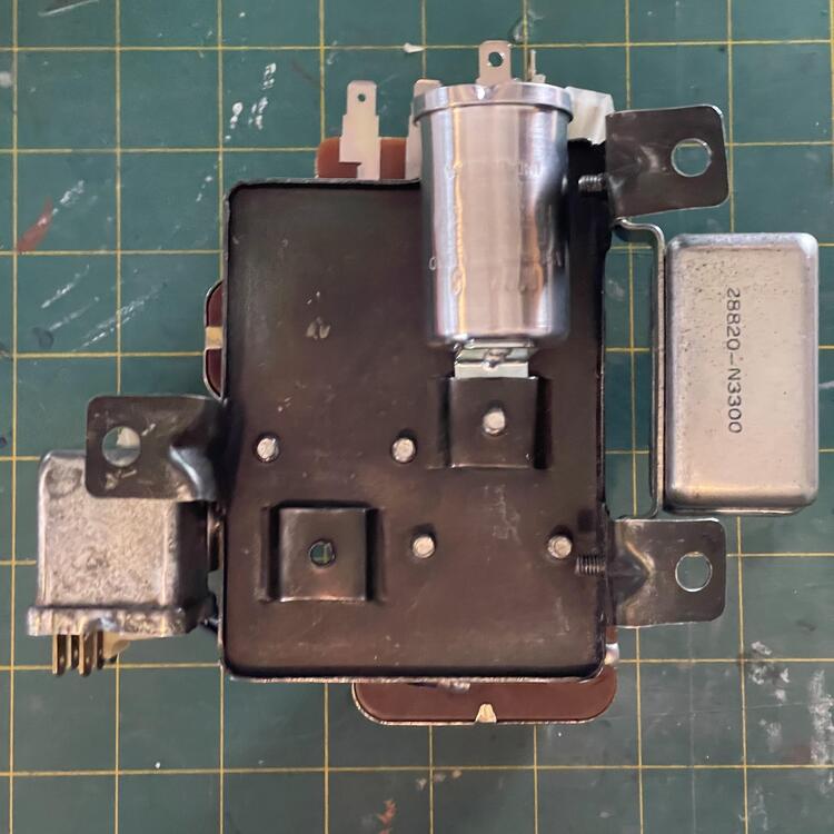
2 pointsWhen I did the restoration on my 73 240Z I purchased a Pertronix ignition to replace the points system. I had problems with it at the time, so I decided to go back to the points system temporarily until I got everything lined out. Got the car up and running late last year and everything seem fine. After setting all winter with only occasional starts, I started having starting problems. To make a long story short (after much frustration) I decided to try to go back and install the Pertronix system. I wanted to be sure it was functioning properly before injecting another problem into my already frustrating situation. So, I called Pertronix to see if there was any way to check the module out before installing it or buying a new one. The tech guy at Pertronix was most helpful and walked me thru a test procedure. I thought I'd pass it on. The test can be accomplished with the module on or off the car. I found it easier to do it on the bench using a 12V motorcycle battery I keep around for testing purposes. You will need a long piece of 14 or 16 ga wire with an allegator clip on each end, a 12V source, and a digital volt meter. Take the wire w/ allegator clips, attach one end to the module mounting bracket; connect the other end to the negative battery post. Set the meter to volts DC. Connect the black meter lead to black wire coming from the Pertronix ignition module Connect the red meter lead, and the red module wire then to the positive battery terminal. Your meter should read 12V. If it does not, recheck your wiring, if it's correct and you're still not reading 12V, Module is bad. If you have 12V, continue the test by passing the magnetic ring pass the ignition module. (use the same orientation of the ring to the module as if it were in the distributor). Watch the meter, each time the magnetic ring passes by the module, the voltage should drop to around one volt or so . If it does, the module is good; if it stays at 12v when passing by, the module is shot. Mine was. I ran this test again when I got the new module and verified the procedure. It worked as described. CAUTION!! DO NOT LEAVE THIS CONNECTED FOR A LONG PERIOD OF TIME OR YOU WILL BURN UP THE MODULE On a related note; you may have seen post cautioning you that if you leave the ignition on without the engine running you will burn up the Pertronix module. This is true and I think this may have happened with my first module. I asked the tech about this and he confirmed it was true. I asked how long it would take to burn up. He said about 2 MINUTES! This does not apply if the car ignition is in the Accessory position.2 points
-
2 points
-
Granny- Pouring over old posts I think I can sum up the clutch adjustment like this. The threaded master cylinder rod is only used for adjusting pedal height. The only problem you can have with pedal height is if the pedal is too low. With a low pedal you may not have enough swing of the pedal to completely disengage the clutch making for tough shifts. Clutch engagement is controlled by adjusting the slave cylinder rod and it seems the best way to adjust that is to extend the rod until you have zero free play then back it off a smidge to ensure you are not riding the clutch all the time. So how I understand it a clutch pedal engaging too low is most likely a misadjusted slave cylinder (too much free play) which could be exasperated by a low clutch pedal (not enough swing of the pedal). So basically your initial movement of the clutch pedal just takes up all the free play but doesn’t actually disengage the clutch until the free play is gone. With a pedal that sits too low by the time you’ve taken up the free play and the clutch is actually beginning to disengage you’ve run out of pedal travel to completely disengage the clutch. Air in the system acts like excessive slave cylinder free play. You have to compress the air before you start moving the fluid and disengaging the clutch. Again, too much air and you run out of pedal swing. One more possibility is failing master or slave cylinders. If the internal seals are failing you’re pushing fluid past the seals instead of moving the cylinder and, again, you run out of pedal swing to take up all the “smoosh” of the air or fluid sneaking past the seals. So to sum up: 1. Make sure you have good master/slave cylinders (not sure? Just replace them— they’re cheap) 2. Bleed the air completely! 3. Use the threaded rod on the master cylinder to set the pedal height, preferably even with the brake pedal and somewhere around 8-9” from the floor 4. Adjust the slave cylinder until there is zero free play then back it off a bit and you should be good2 points
-
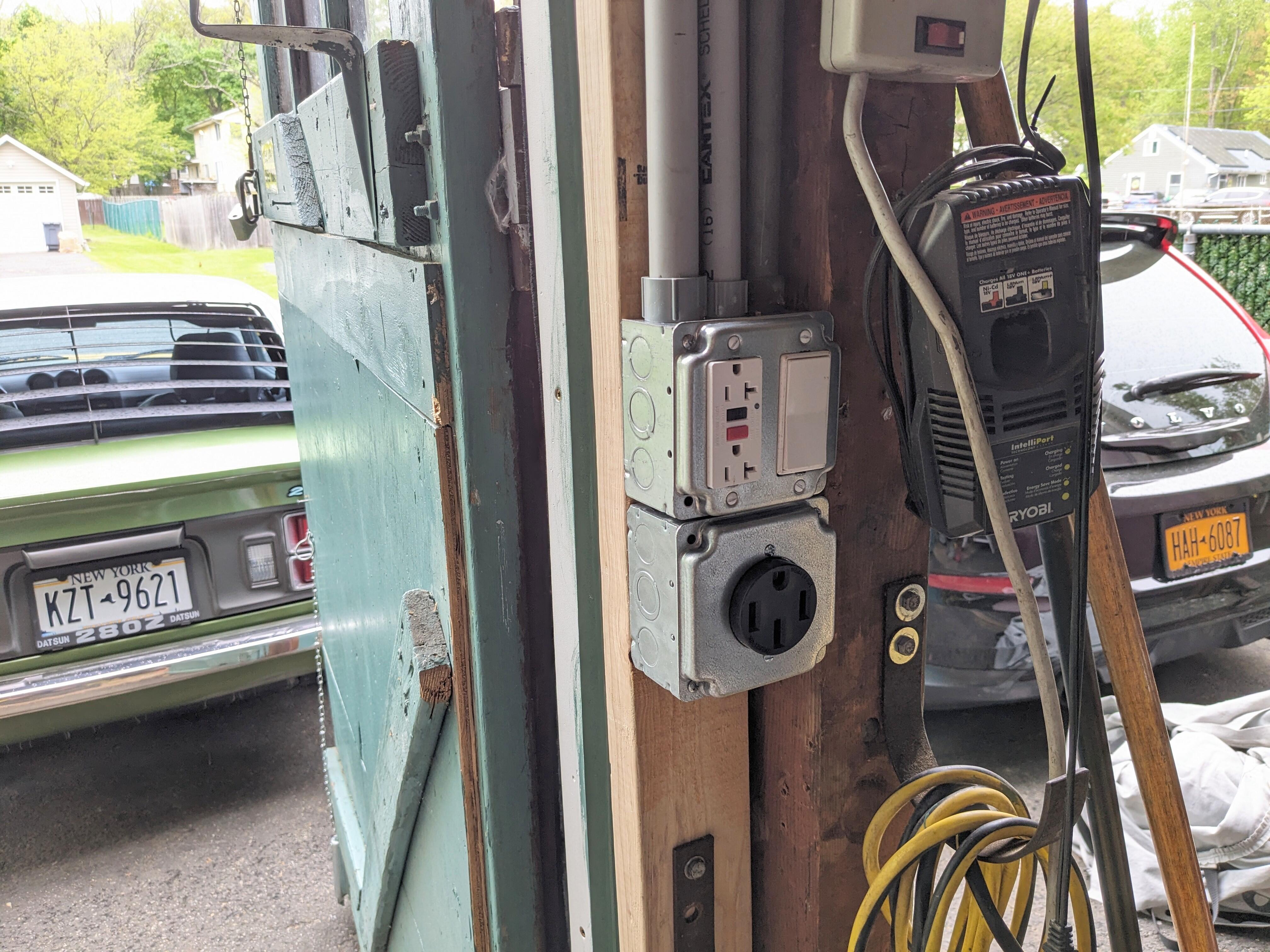
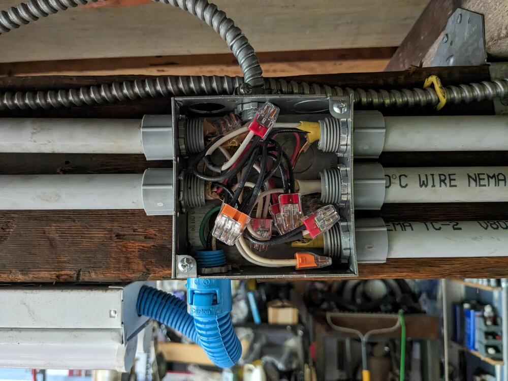
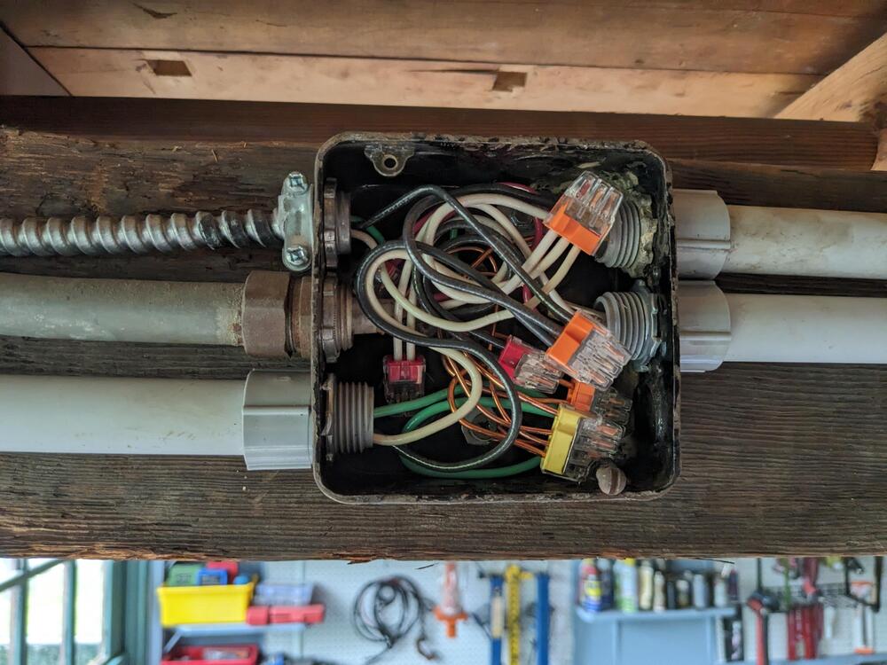
Small amount of work accomplished today, between chores & visit from a good family friend who had moved upstate. Go the junctions on the center beam connected for the attic lighting branch, the overhead lighting, and the outlet on the me main door post. Also ran the 3/4 conduit from that box up & over to the south wall, where it will ultimately connect to the feeder branch coming down the south west corner post. Separated all the 12/2 and 14/3 wiring into their own conduit. I worked in layers starting with the grounds, then neutrals, then travellers, switch outputs and finally the hot feeds Had to make schematics for each junction, to make sure I didn't mis-connect anything, having a 3way switched circuit for one branch of the lighting makes me check 3 times at least. Hopefully get more done than this tomorrow.
 2 points
 -
2 points
-
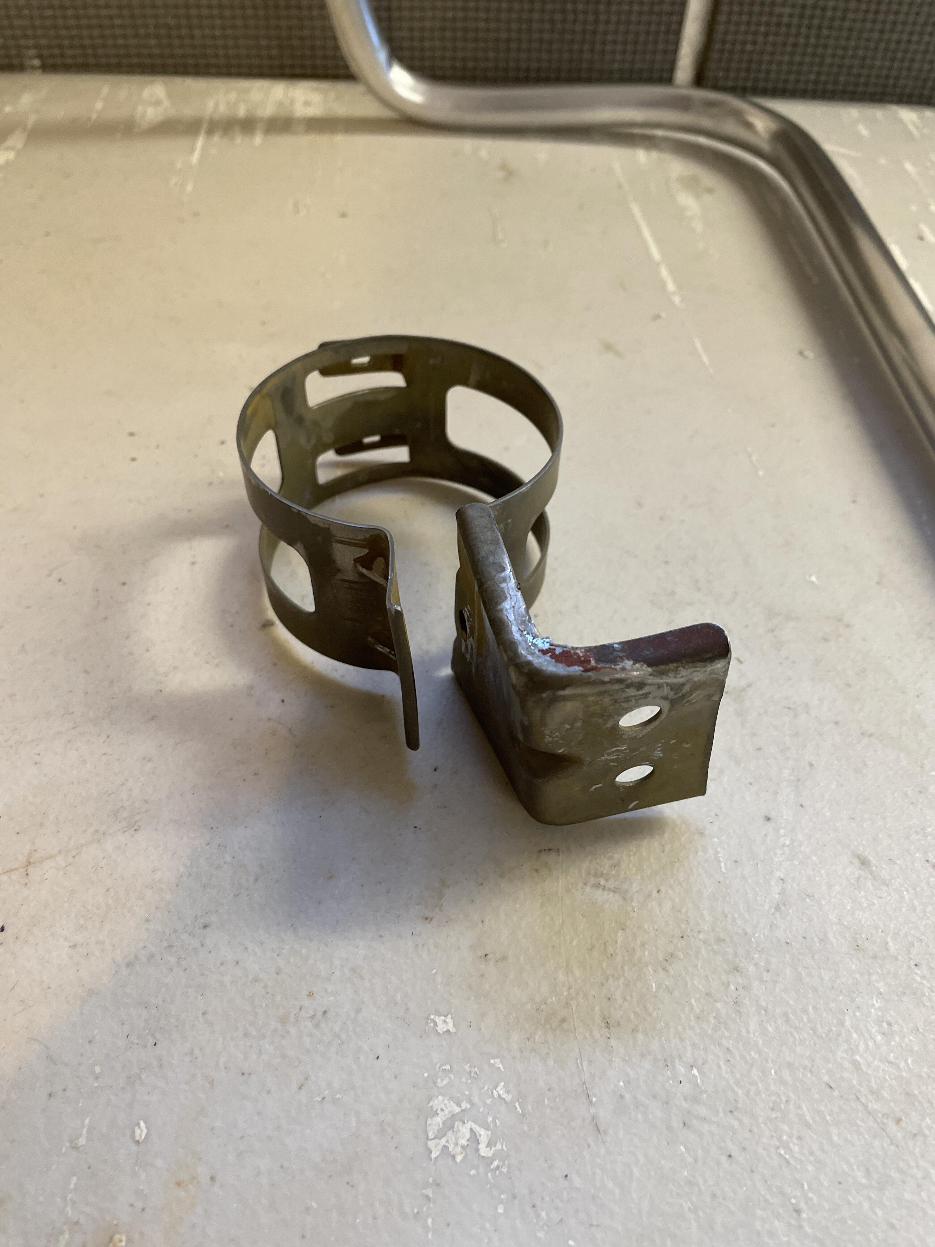
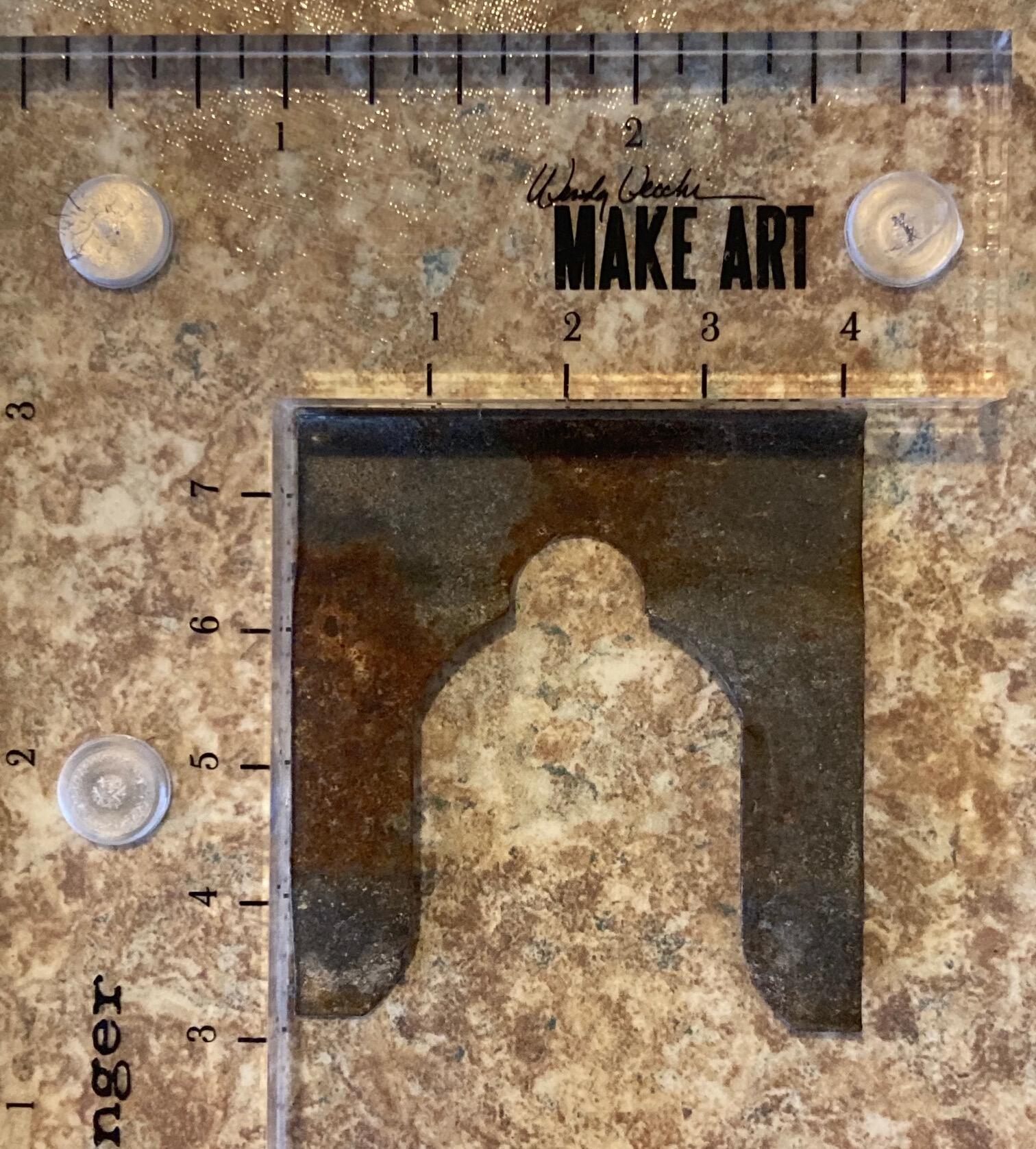
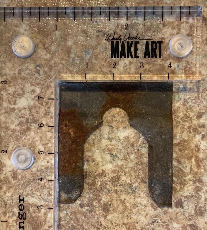
2 pointsThat one you linked to at ZCD is too small for the hatch lock. It is for the early Series One fuel door latch. Apparently ZCD didn't offer one my bad ^^ I tried MSA and they list one but it is out of stock. (discontinued, same at Nissan) I do have this one, as you can see it is the largest clip on the car. A little clean up needed.
 2 points
 -
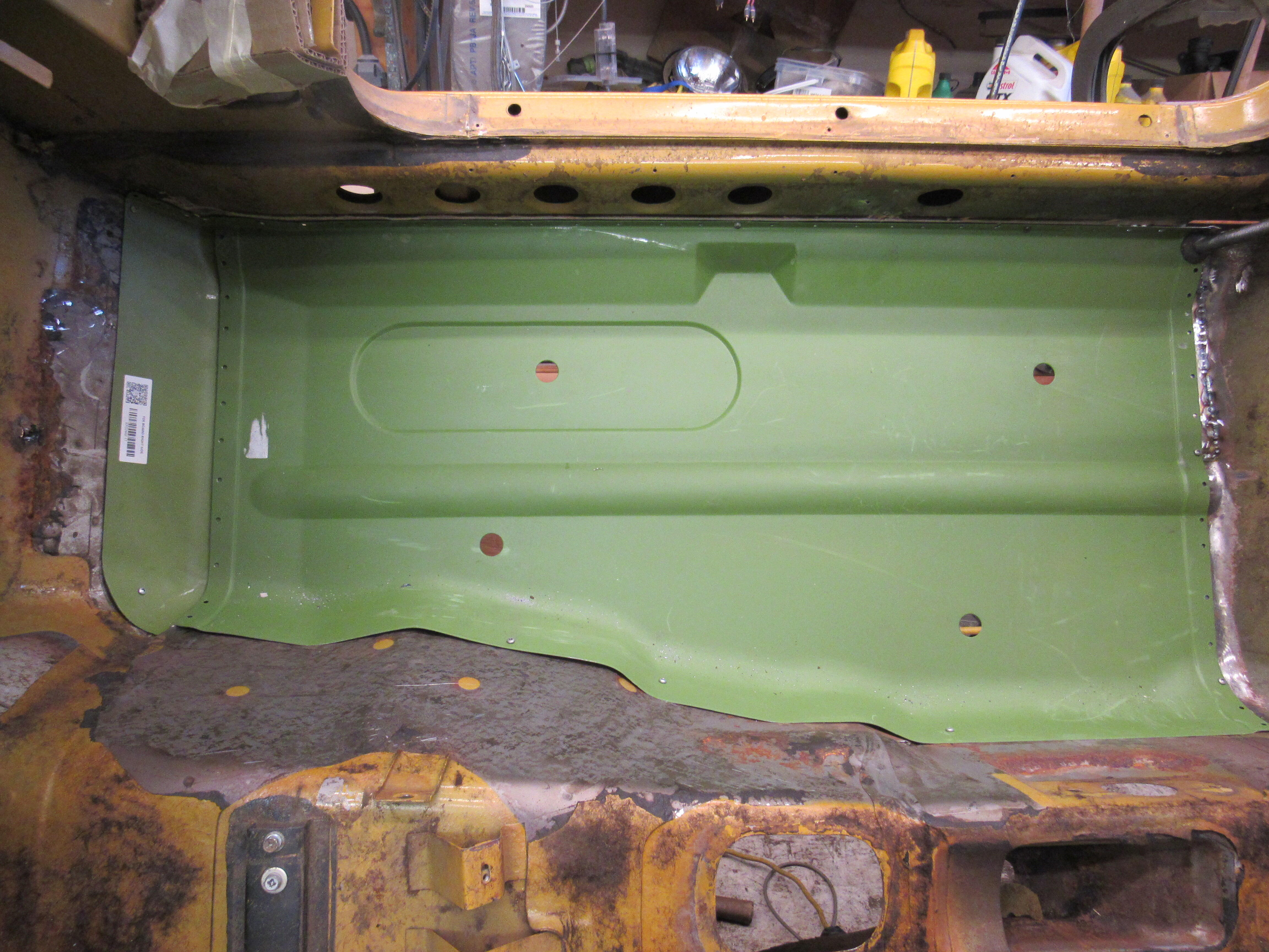
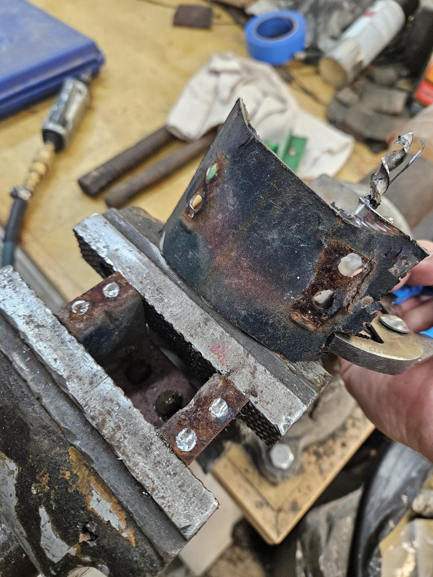
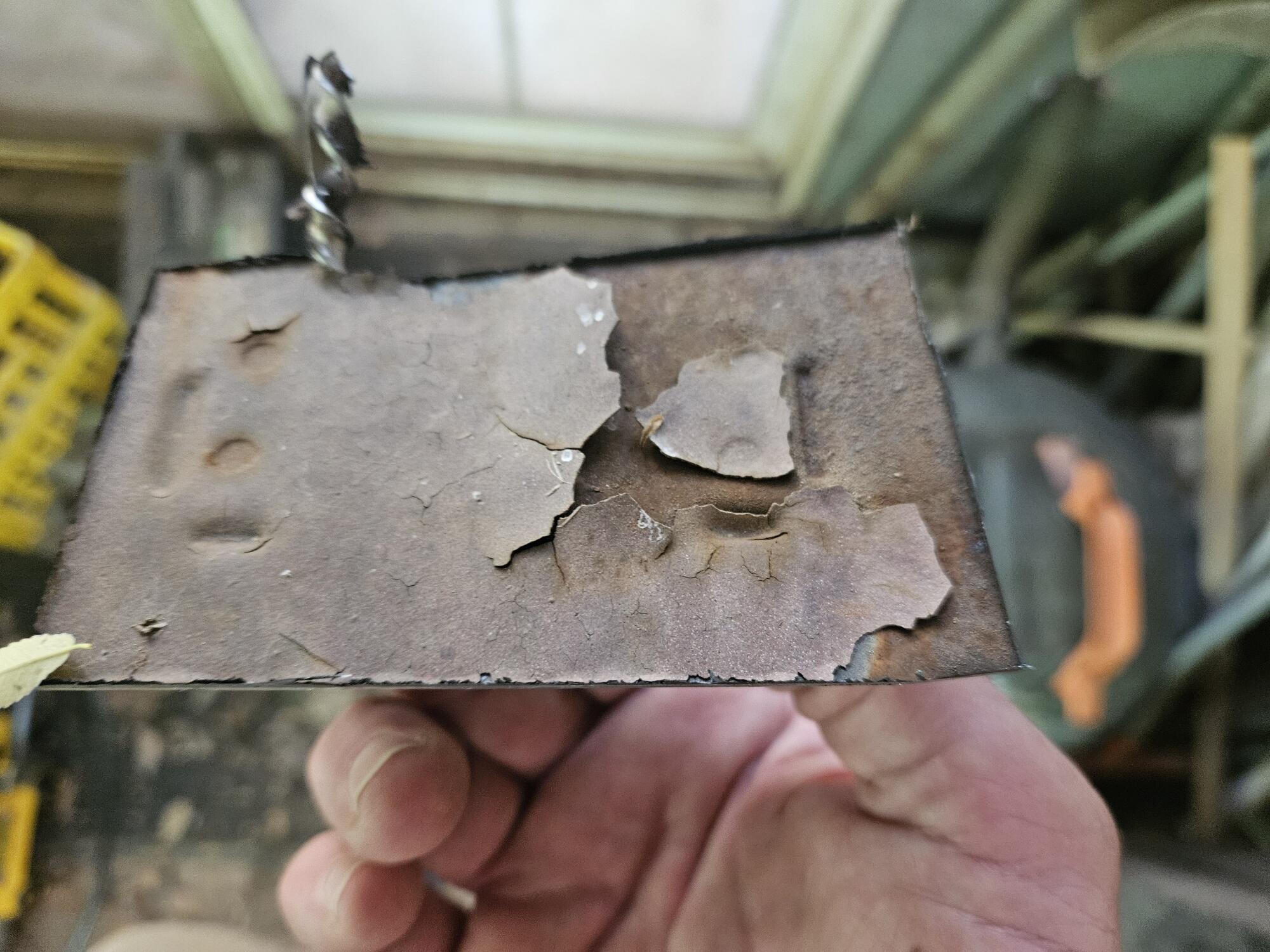
It looks like they cut close to where they have the black marker line above the previous welded seam, I can't say for sure what technique they used but it is common to fit the new pan as close as possible to the original metal as below, then with a thin cutoff disc cut through both layers of metal at the same time. That results in a seam that is matched above and below.
 2 points
 -
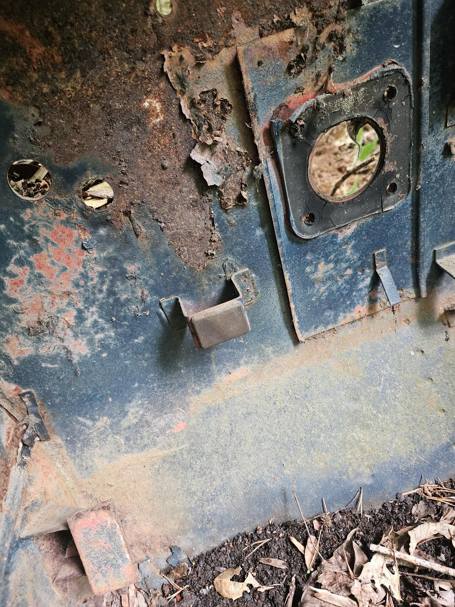
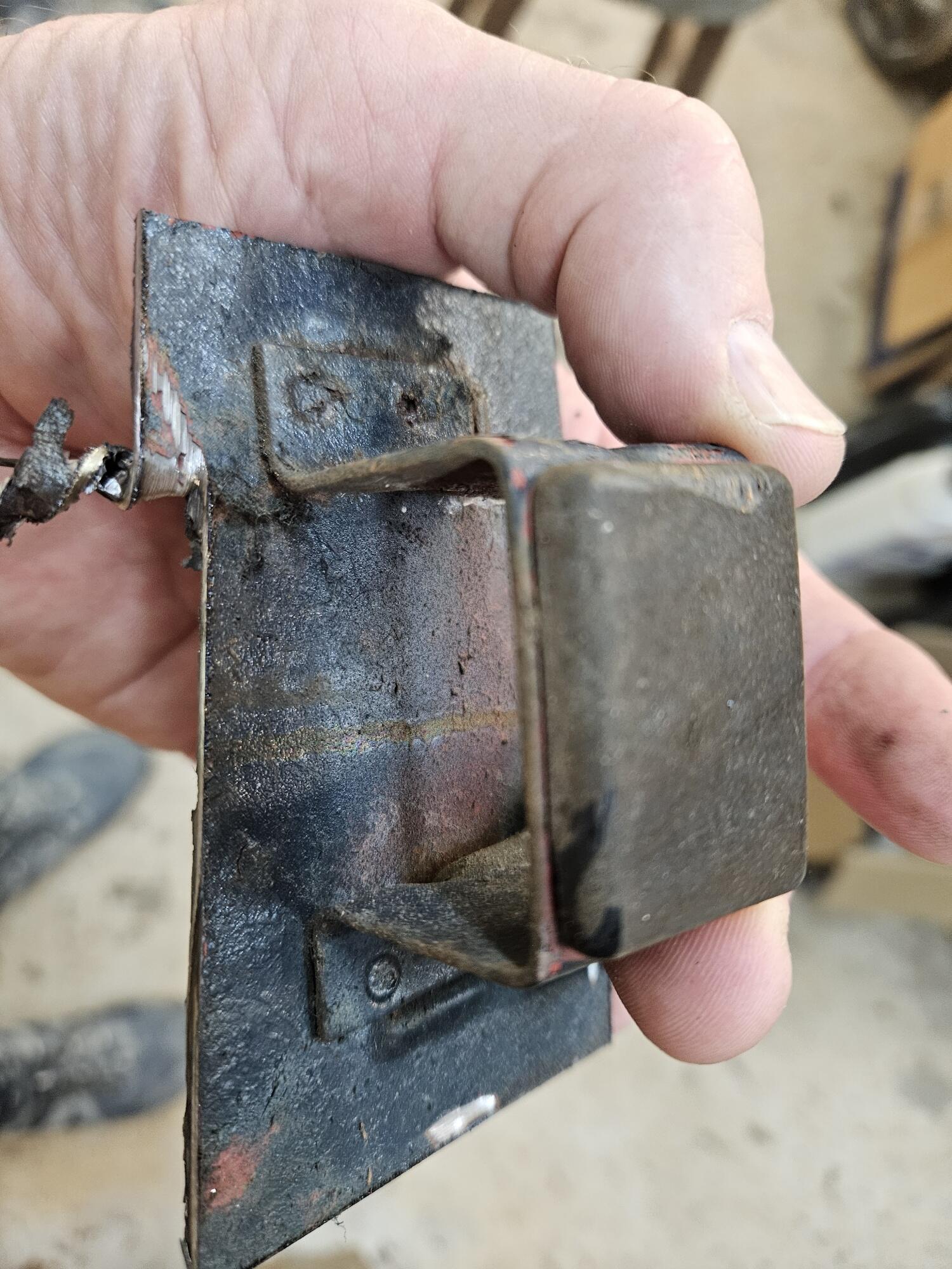
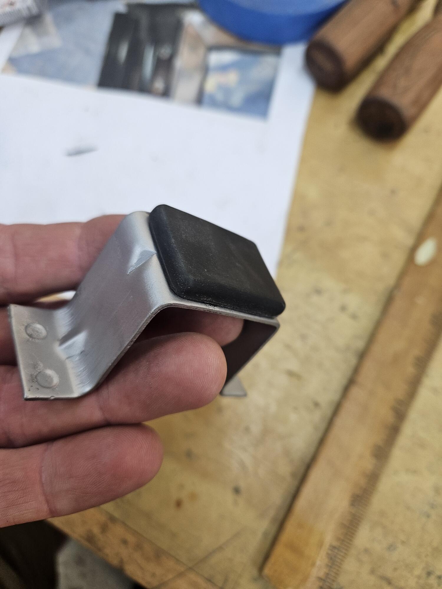
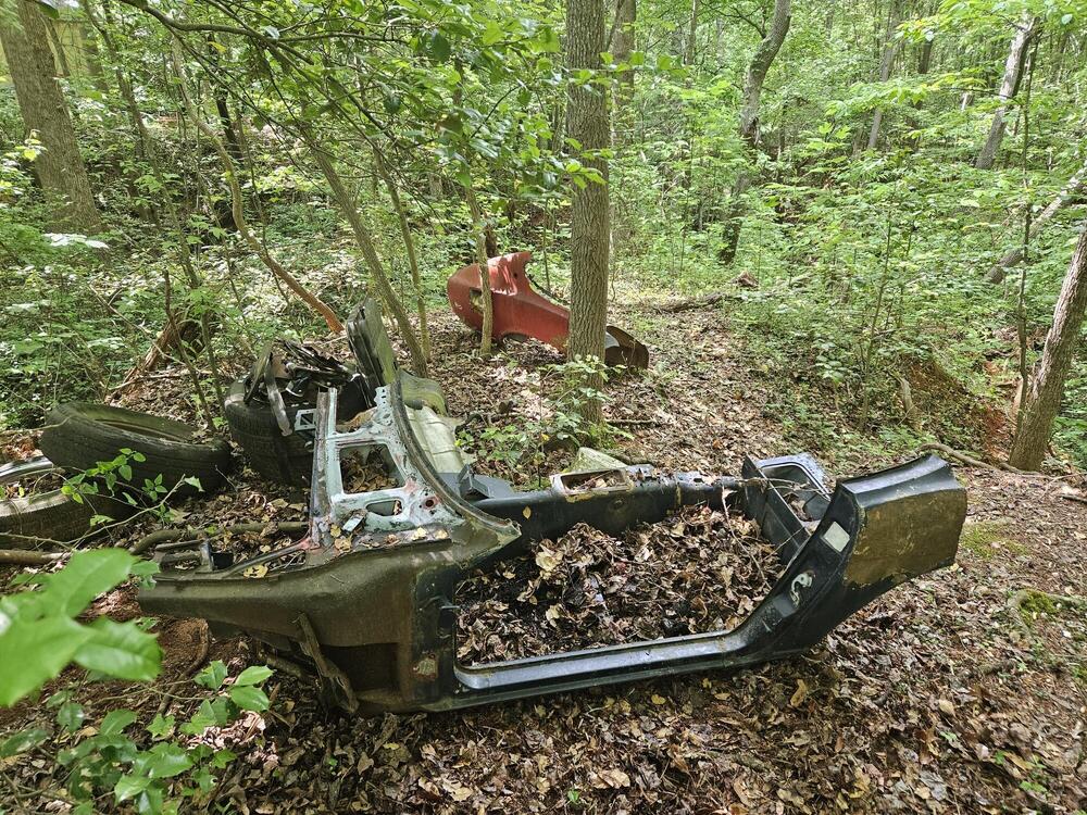
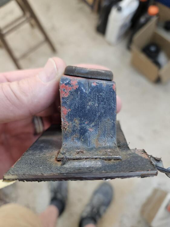
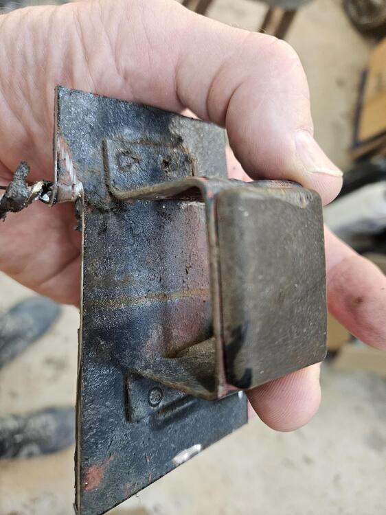
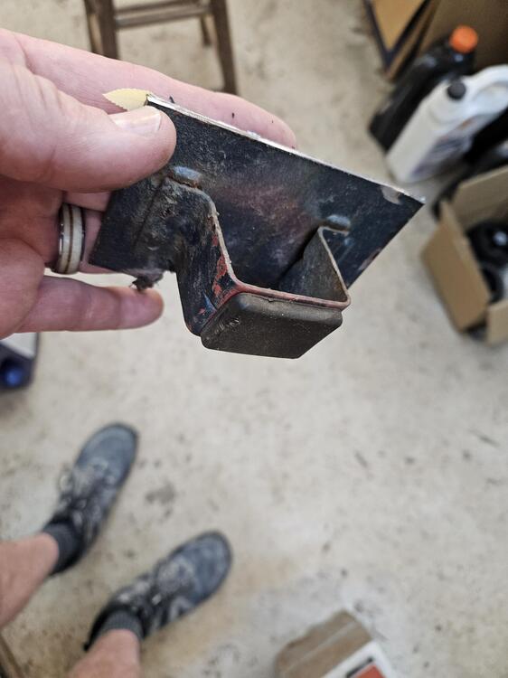
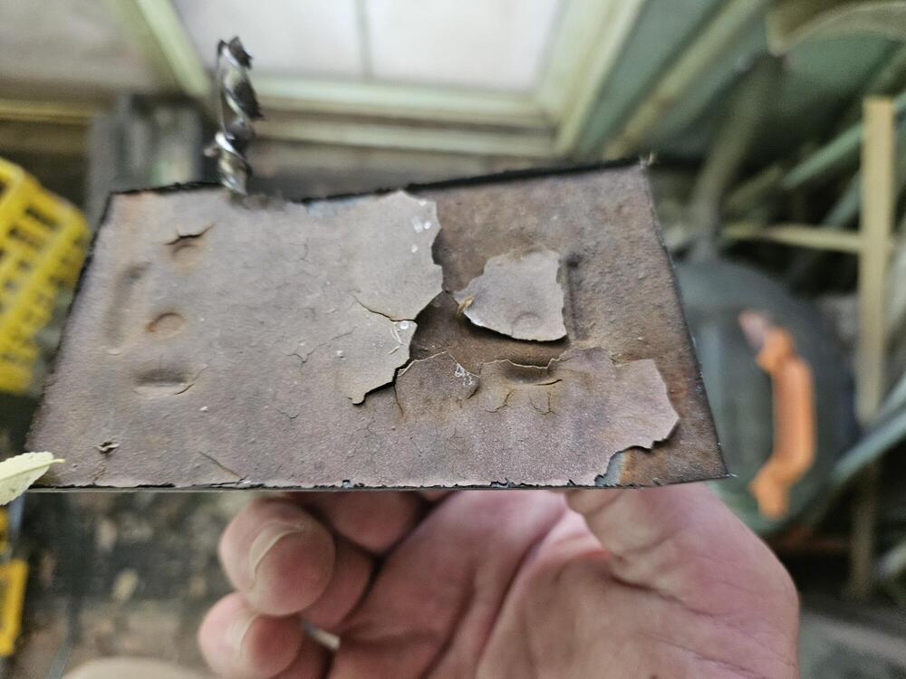
1 pointI got the clutch master in today. I need to check pedal height... I went down to the parts yard and took a clutch pedal stopper off of "Rust in Pieces" \ There are locating dimples in the floor board to locate this part. You can see them from wheel well side. Short edge is the top My favorite tool for spots welds Bead blast Started welding up the hinge pocket


 1 point
 -
1 point
-
1 pointCO had a good suggestion here. Stop messing around with that spaghetti-nest of wires. Confirm that you will be able to create spark with just the coil and distributor and coil and plug wires that you have. Disconnect ALL of the harness power wires to the coil. Let them hang, with the ends protected so that you don't have a short circuit. Start with a bare coil, no power or ground wires attached. Run a long wire from the battery positive to the coil positive post. Connect the wire from the distributor (the points inside the cap) to the coil negative post. Crank the engine over using the key or using a remote starter. You'll be doing what old-time car thieves do. Mess around with this setup until you get spark. The pictures of those nasty crusty wires and connections aren't helping at all. Simpify things down to the bare essentials. If you can't get spark with a single hot wire from the battery you'll never get it from any of those in that pile of wires.1 point
-
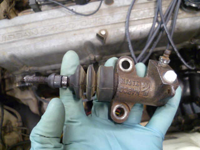
And now that I look at my own pic of the slave I think if I adjust the pivot ball backward toward the slave cylinder that should make it engage later?1 point
-
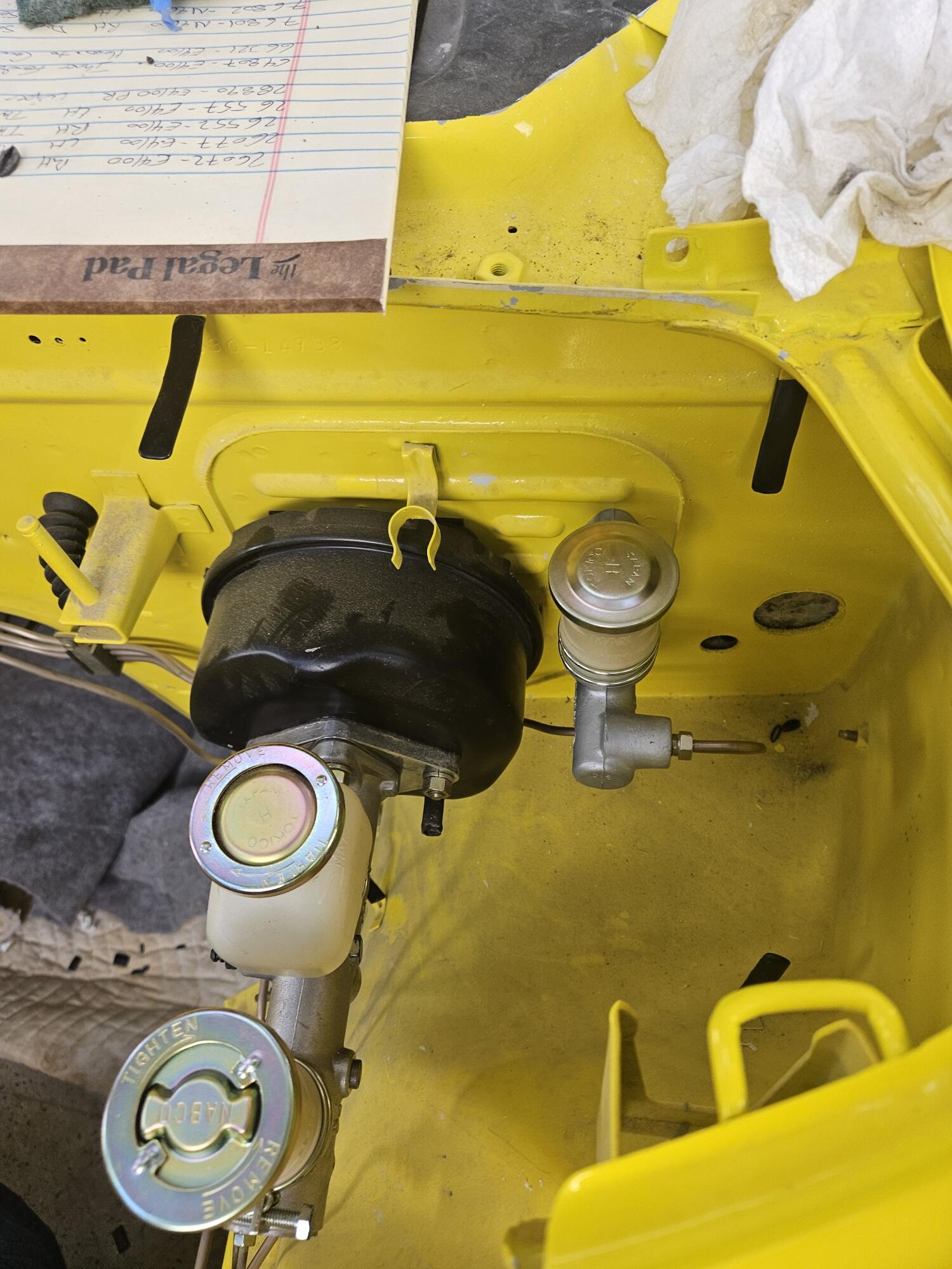
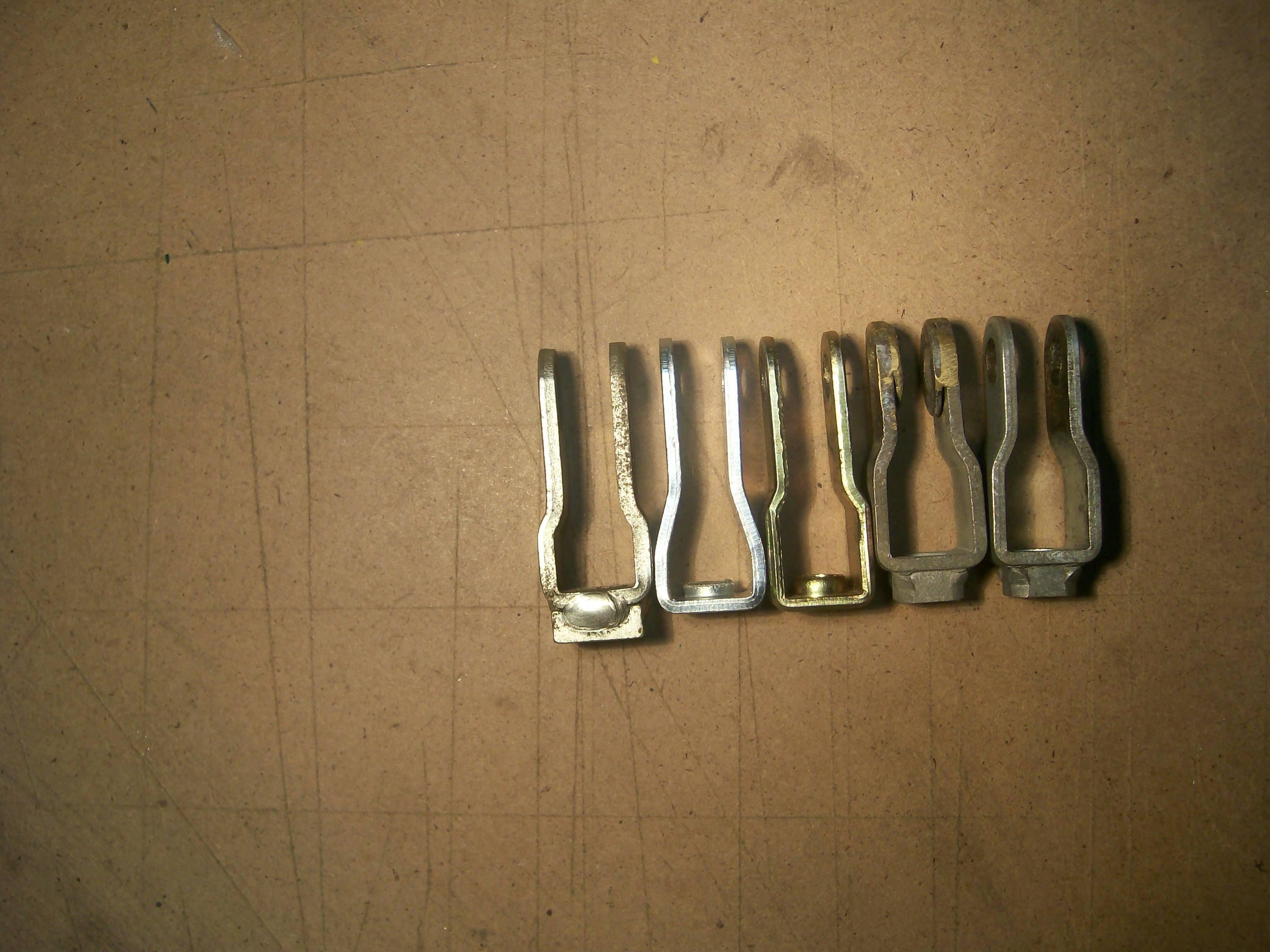
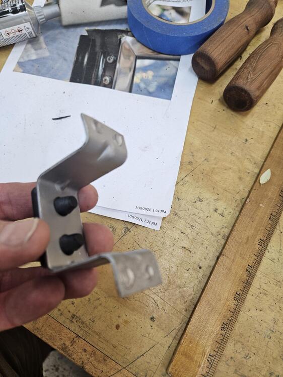
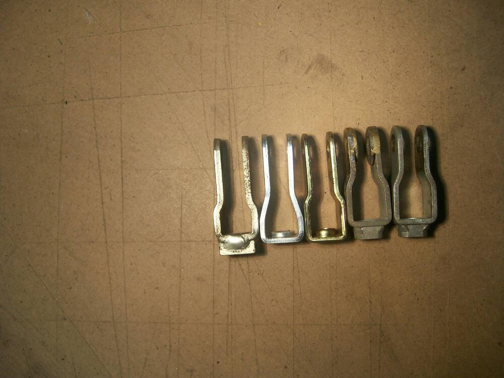
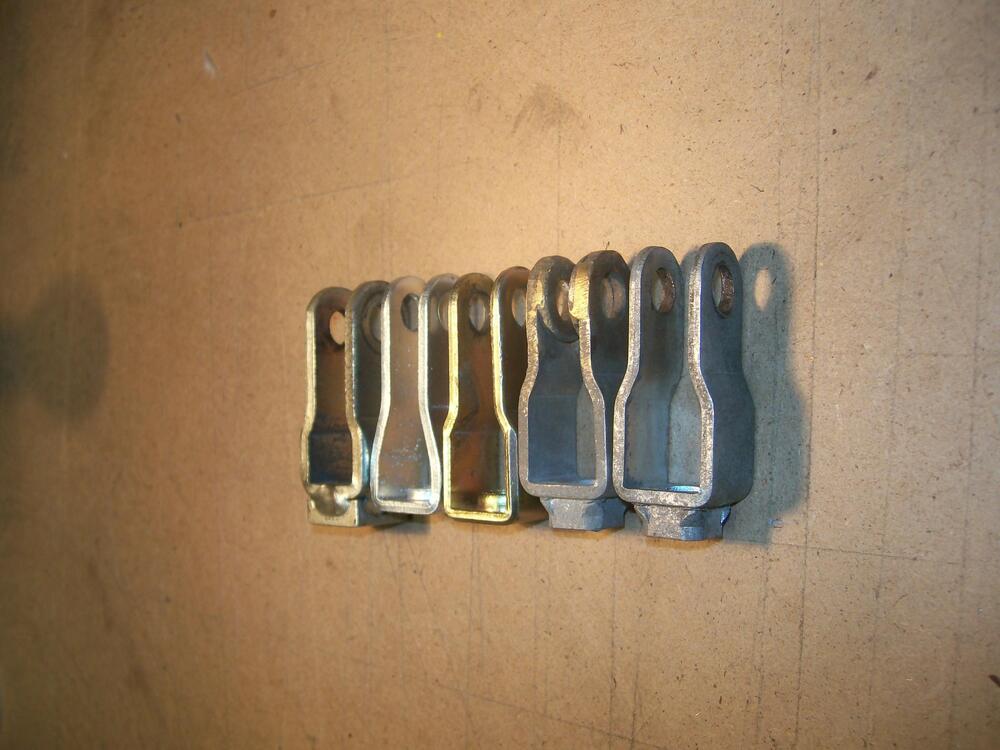
These three photos may provide some additional insights... although they may just add to the confusion. I have four master cylinders and two Mastervacs in my parts collection. I've discovered that these have provided me with three different pushrod designs and three different clevis designs (although I can't say for certain whether they're all Nissan OE parts). Mixing them up creates the potential for 9 different geometries...
 1 point
 -
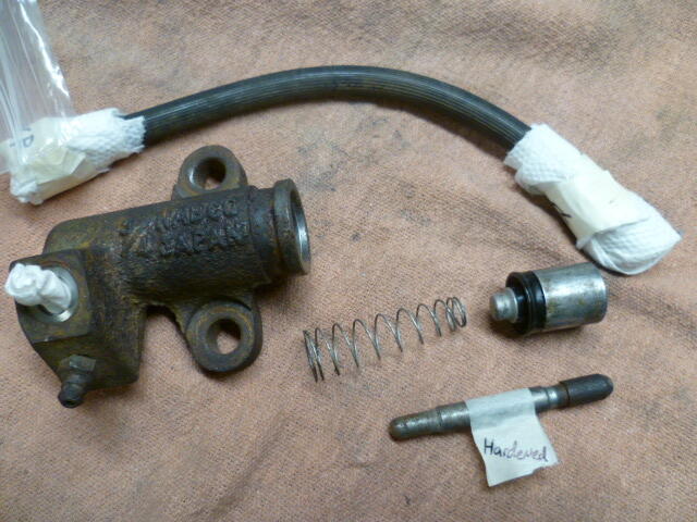
Granny, Are you using an older "non-auto adjusting" slave with the threaded rod, or are you using the newer self adjusting style? Old style: New style:
 1 point
 -
1 pointI believe I understand your first three tests and they produced the expected results. Nothing surprising there. I wish you would stop using "continuity" and give an "Ohms" reading instead, but I suspect the results would still be favorable. As for test #4, This part "While my test light was attached to pos battery. I got light when connected to neg side of points." makes sense to me, and is the desired result. But you kinda lost mo after that. I mean, I know what you mean that the points opened and closed (I assume yo (u were cranking the motor over with the starter), but I don't know what you mean by this part "got no power on other side of points". Where did you have the test light connected, and what did the light do? And for your test #5, repeat that test, but try holding the coil wire near (but not touching) the ENGINE instead of the frame. I believe it has been previously identified that you may not have proper grounding connection to the body (frame), but you do have a well grounded engine. The valve cover or intake manifold should be a suitable grounded location to use to repeat the test.1 point
-
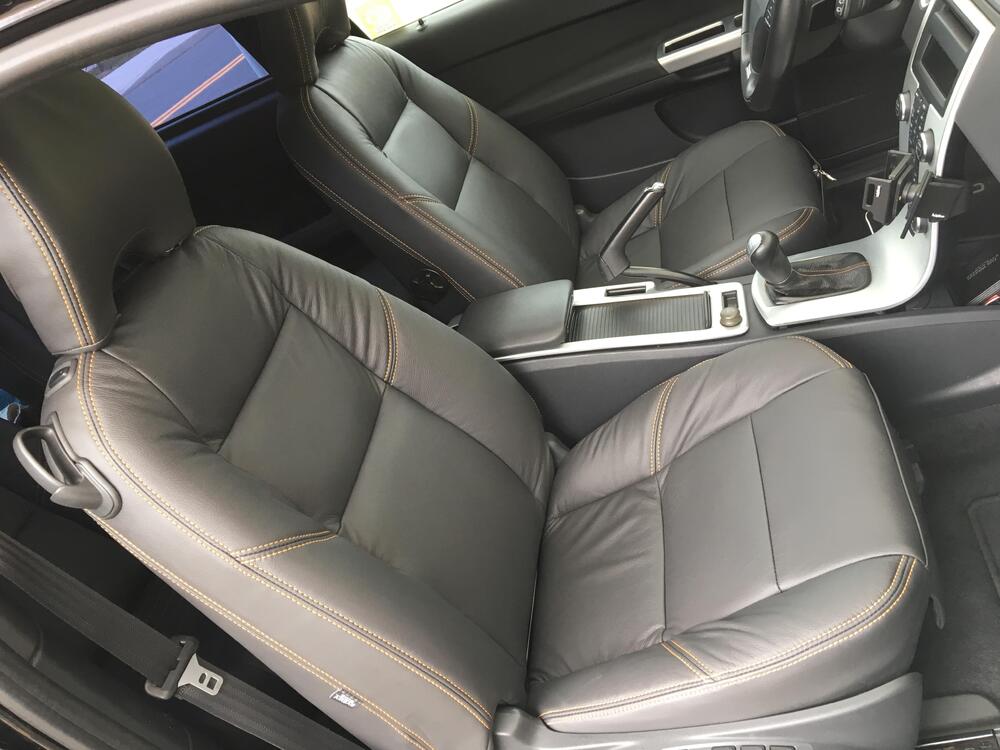
It's a great car - interior is quite unremarkable (Ford era Volvo), however for my size it is extremely comfortable & pedal position, etc., is perfect. I don't have any interior pics besides a couple from when I replaced the upholstery with leather. It is 6 speed manual. I converted it to AWD after putting a larger turbo/tune in it, as FWD just gave too much wheelspin . Plenty of exterior pics, it's a good looking form 😁
 1 point
 -
1 point
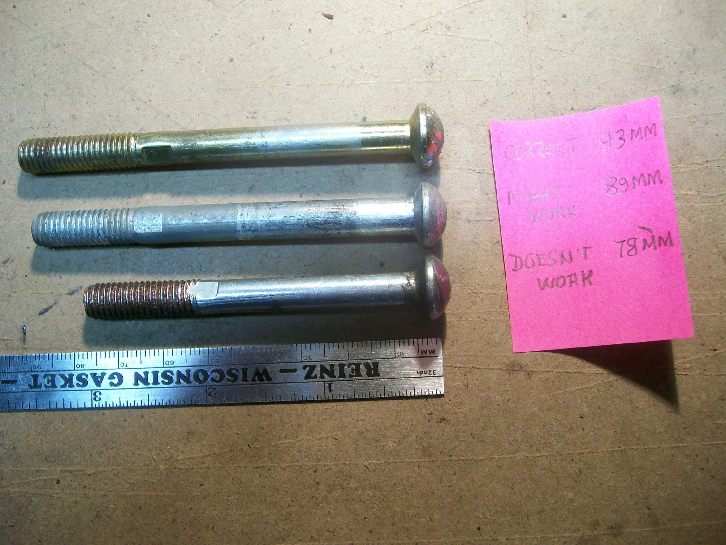
-
I just went through this exact same situation. Couple comments... First, there is supposed to be a rubber bumper stop to limit the "up" position of the clutch pedal. It appears to be missing on your assembly. That bumper is important so you aren't relying on the integrity of the little retainer clip that holds the actuator rod into the master cylinder to establish the up-stop. Second, I found the same as you that the down position was not even close to bottoming out the master cylinder, even when the pedal was all the way down. And that's good... You don't want to bottom out the master. Third, I had three masters here, and all three had different length rods. A Luk aftermarket replacement (same as what you have) was the longest. So for me, I adjusted the up-stop such that the clutch was the same height off the floor as the brake. It's less than 8.5 inches, but it matches my brake pedal. And between having the pedal at that height and having the push rod adjusted to it's maximum, mine lined up OK.1 point
-
1 pointI know it seems a simple thing but make sure the coil wire is going all the way into the coil. The rubber cap can slip down when removing and if you don't reseat it it will not make the connection. Pull the cap back and confirm the two metal bits are contacting fully. Then check spark. You can also take one of the plug leads and put it in the coil hole again seated, then put a plug in the other end and rest the plug on the head, crank it and check for spark. If you do have a bad coil wire it will give you another confirmation the wires are is or isn't the problem.1 point
-
1 pointDid you do that hotwire test yet? Once we know the results of the hotwire test and we are confident that everything from the ballast resistor, through the point, to the high tension coil wire is working correctly, we can focus our efforts upstream from there. Break the problem into small manageable pieces.1 point
-
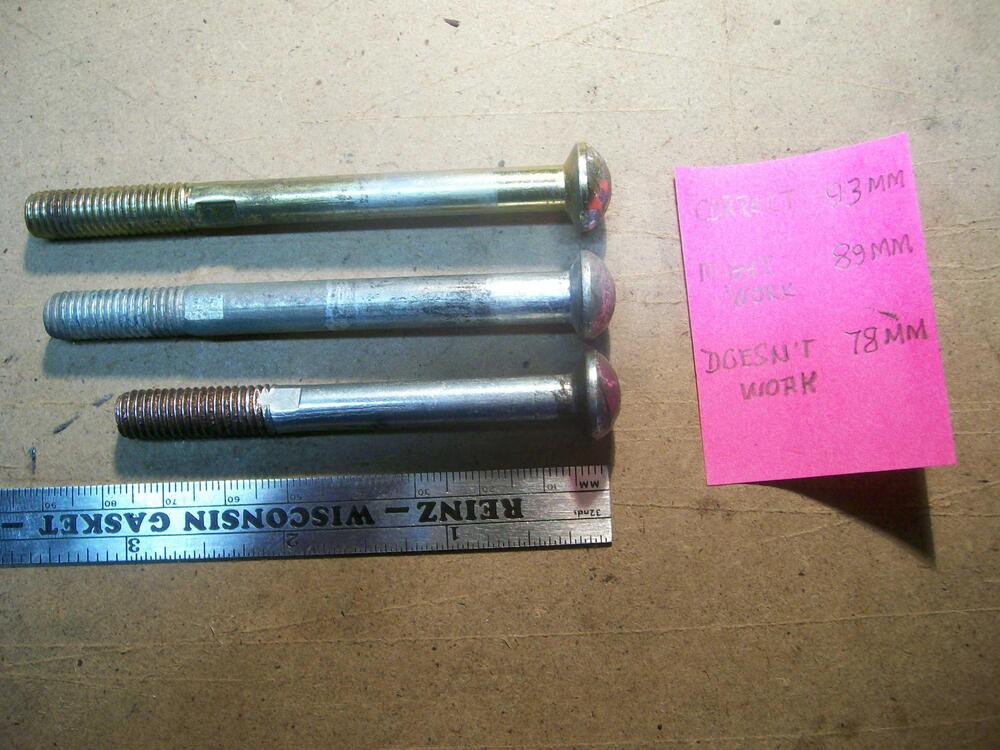
1 pointI have purchased hardware from belmetric on line, and they even have all metric hardware in yellow zinc.1 point