Leaderboard
-
duffymahoney
Free Member9Points961Posts -
conedodger
Free Member6Points12,513Posts -
Captain Obvious
Free Member5Points10,081Posts -
inline6
 Subscriber
 5Points1,282Posts


Popular Content
Showing content with the highest reputation on 02/07/2024 in all areas
-
5 pointsA little web digging turned up some search terms that might be helpful. FR-2 (predecessor to what we use today which I believe is FR-4) And a couple brand names: Pertinax Paxolin5 points
-
5 pointsI launched my Datsun parts company, for anyone looking. https://www.m2racing.com/5 points
-
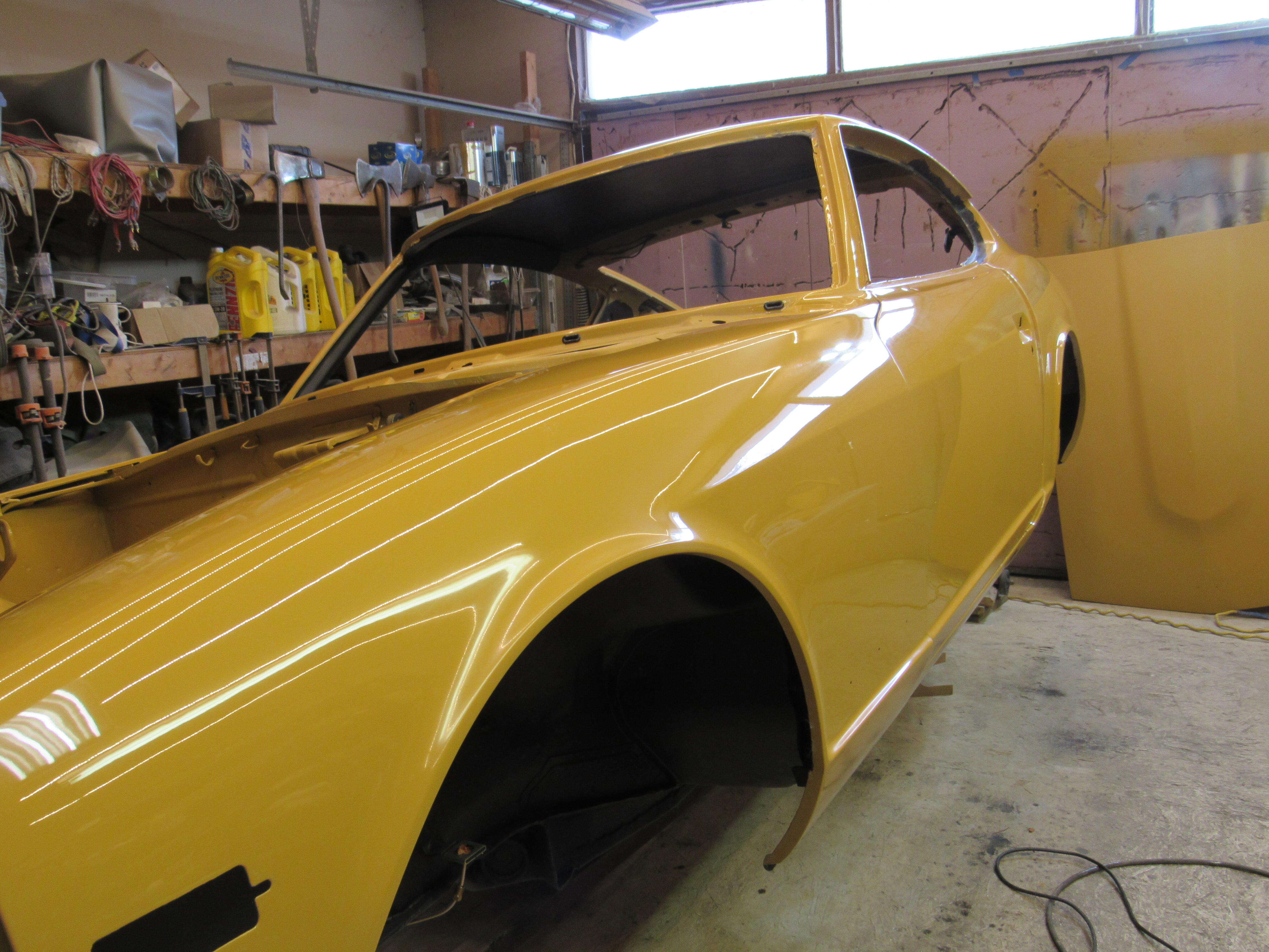
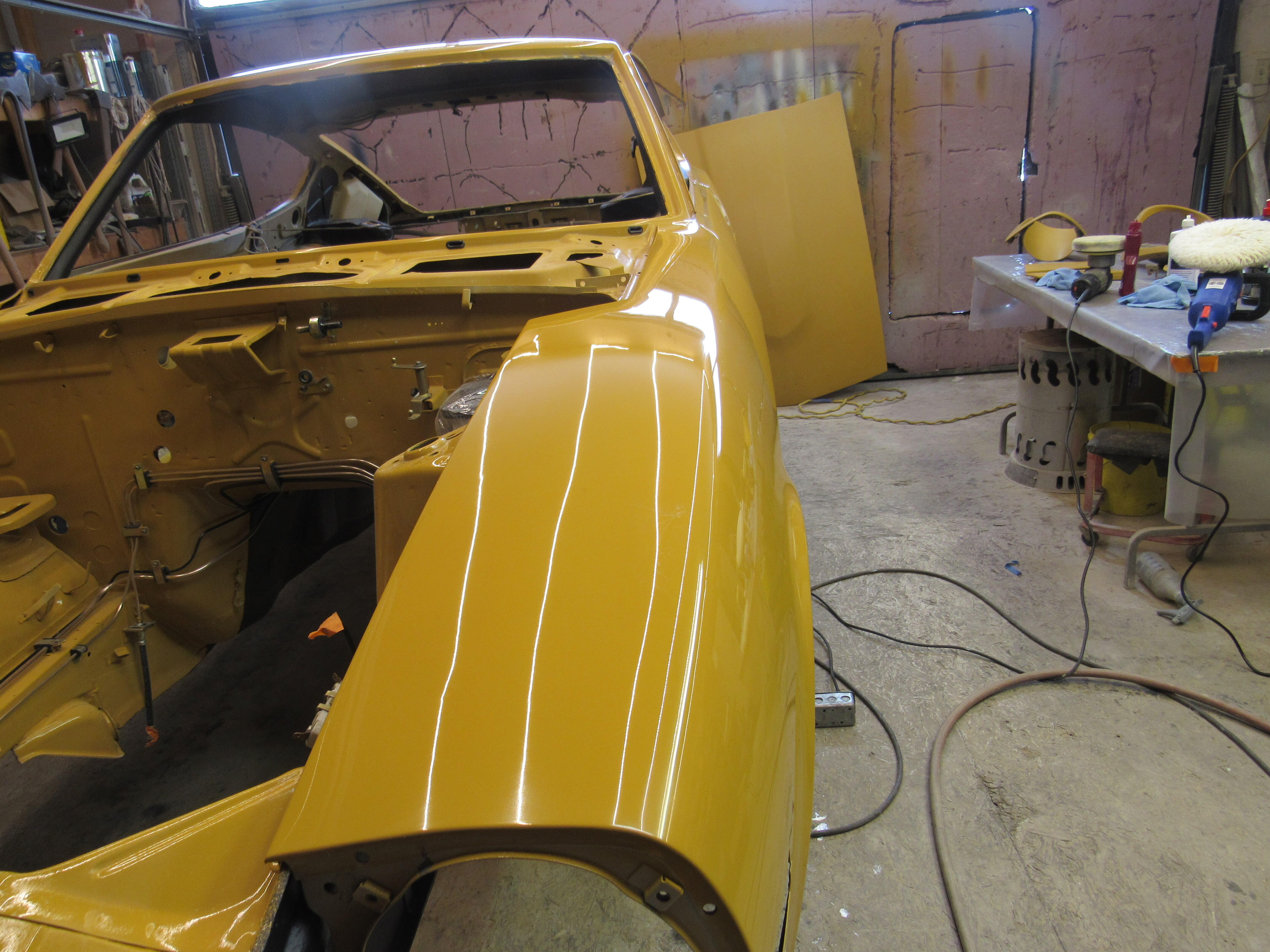
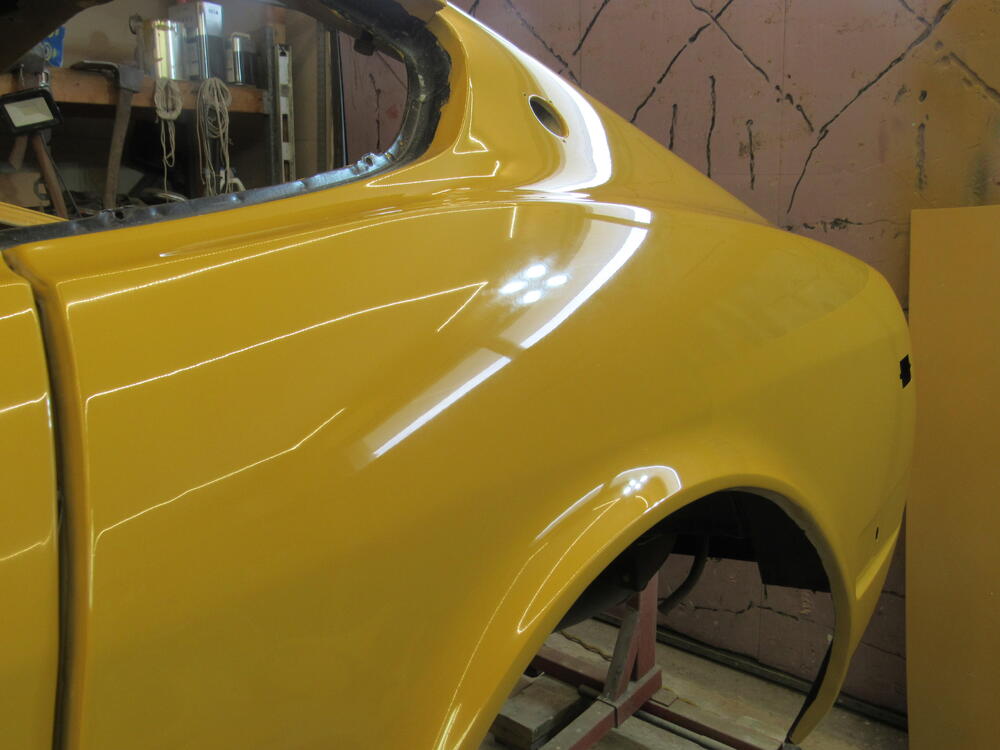
3 pointsI got the D/S, roof, hatch and all the smaller pieces done today, just have the P/S and hood to go.


 3 points
 -
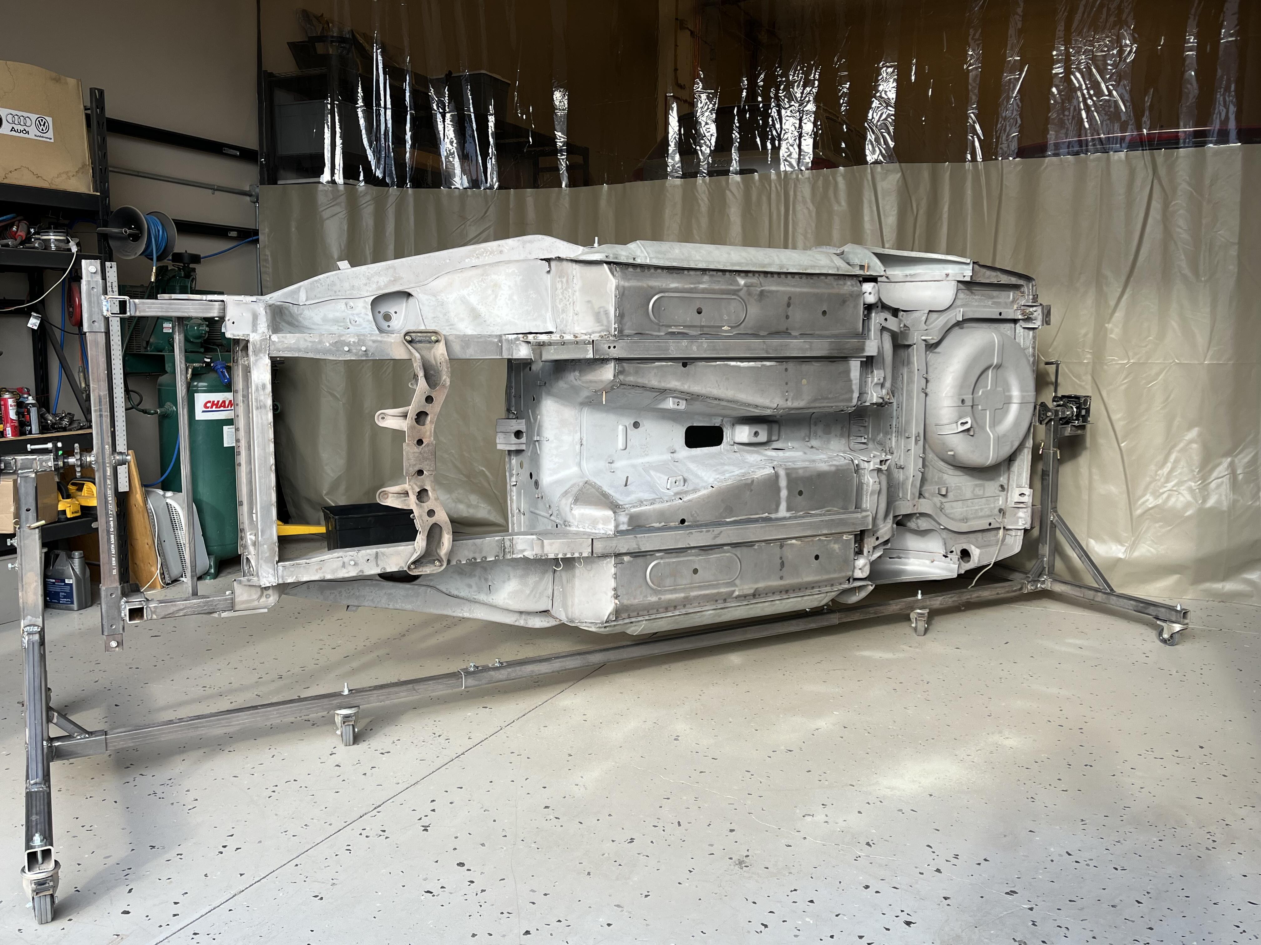
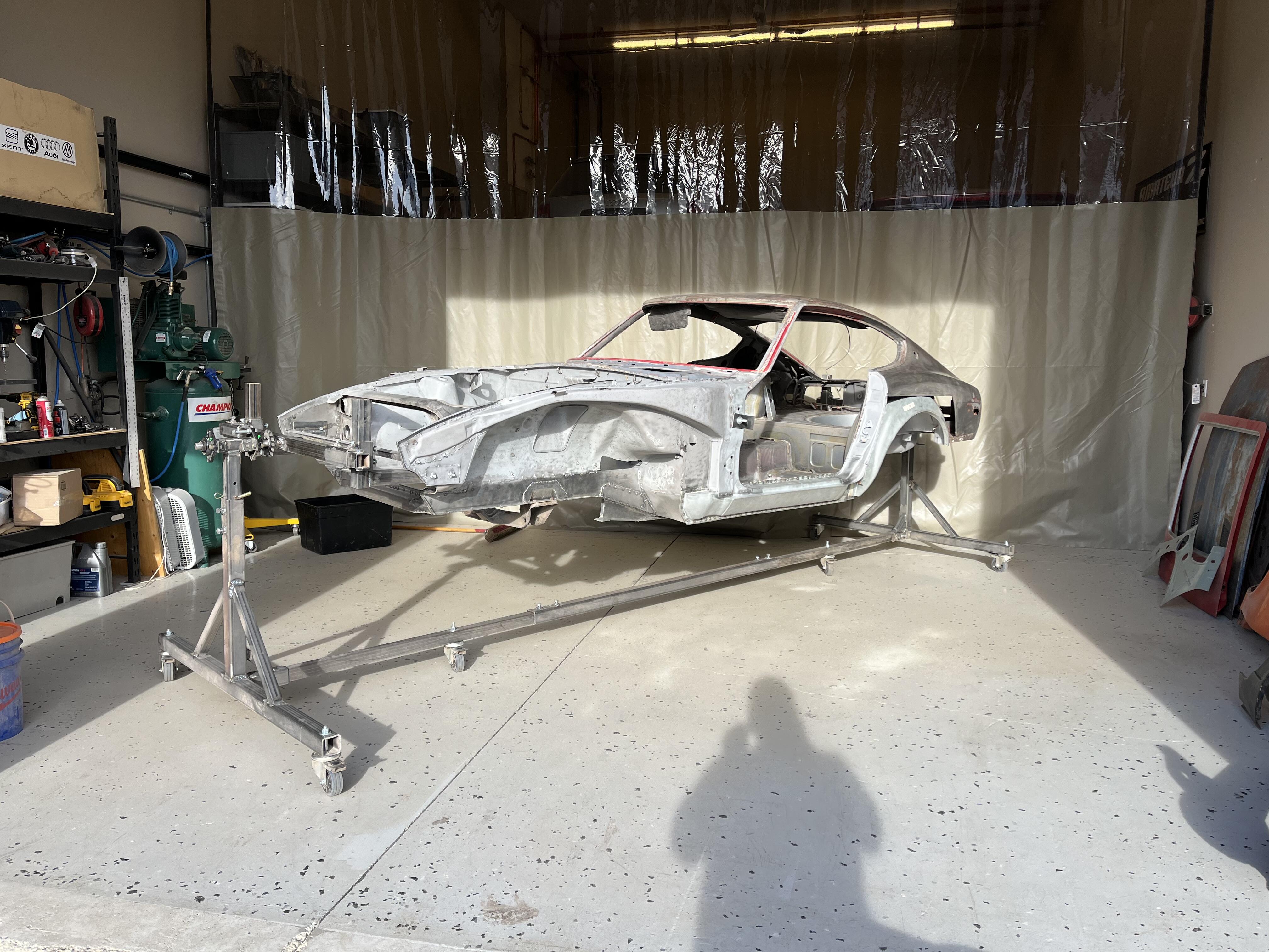
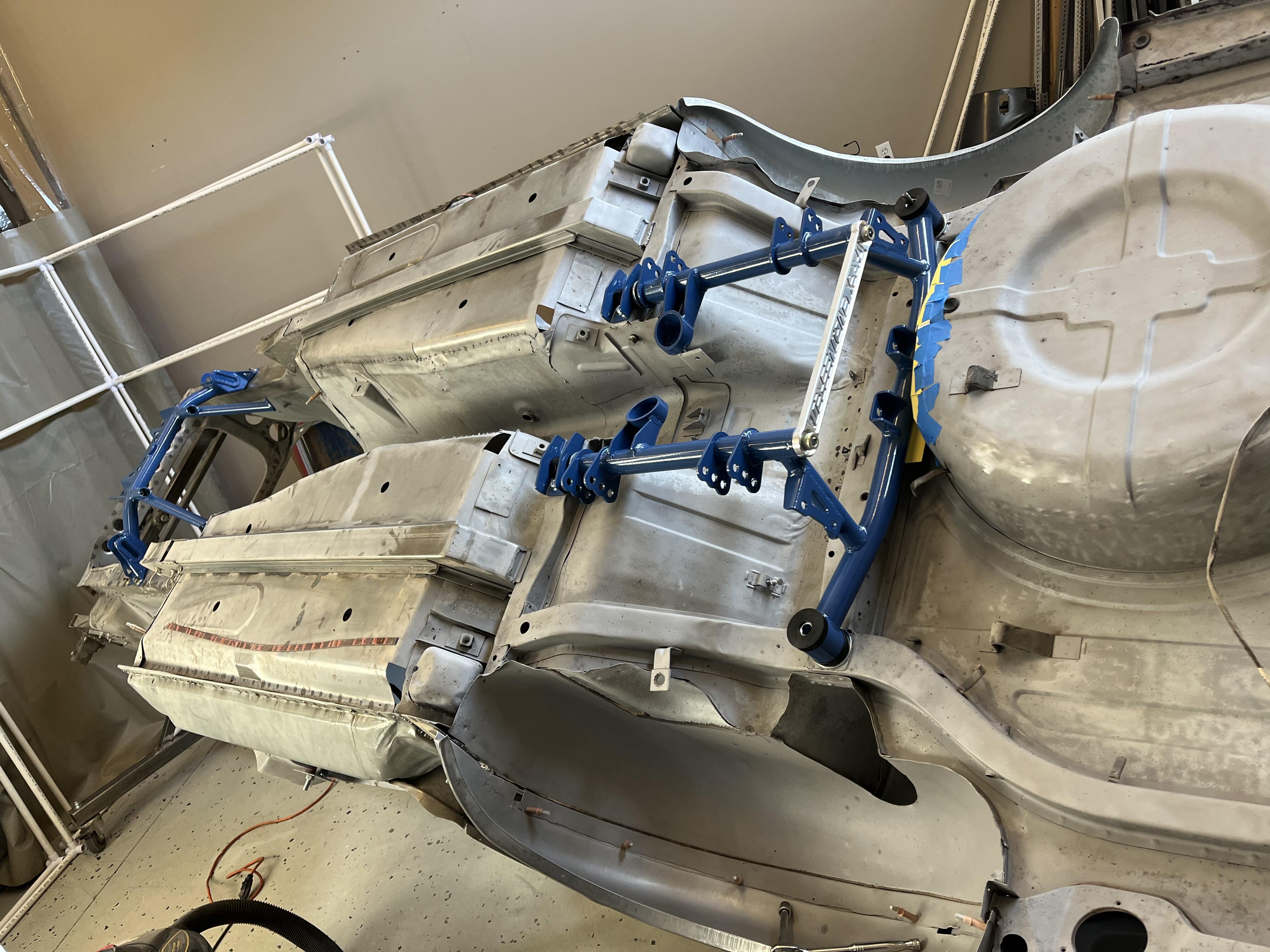
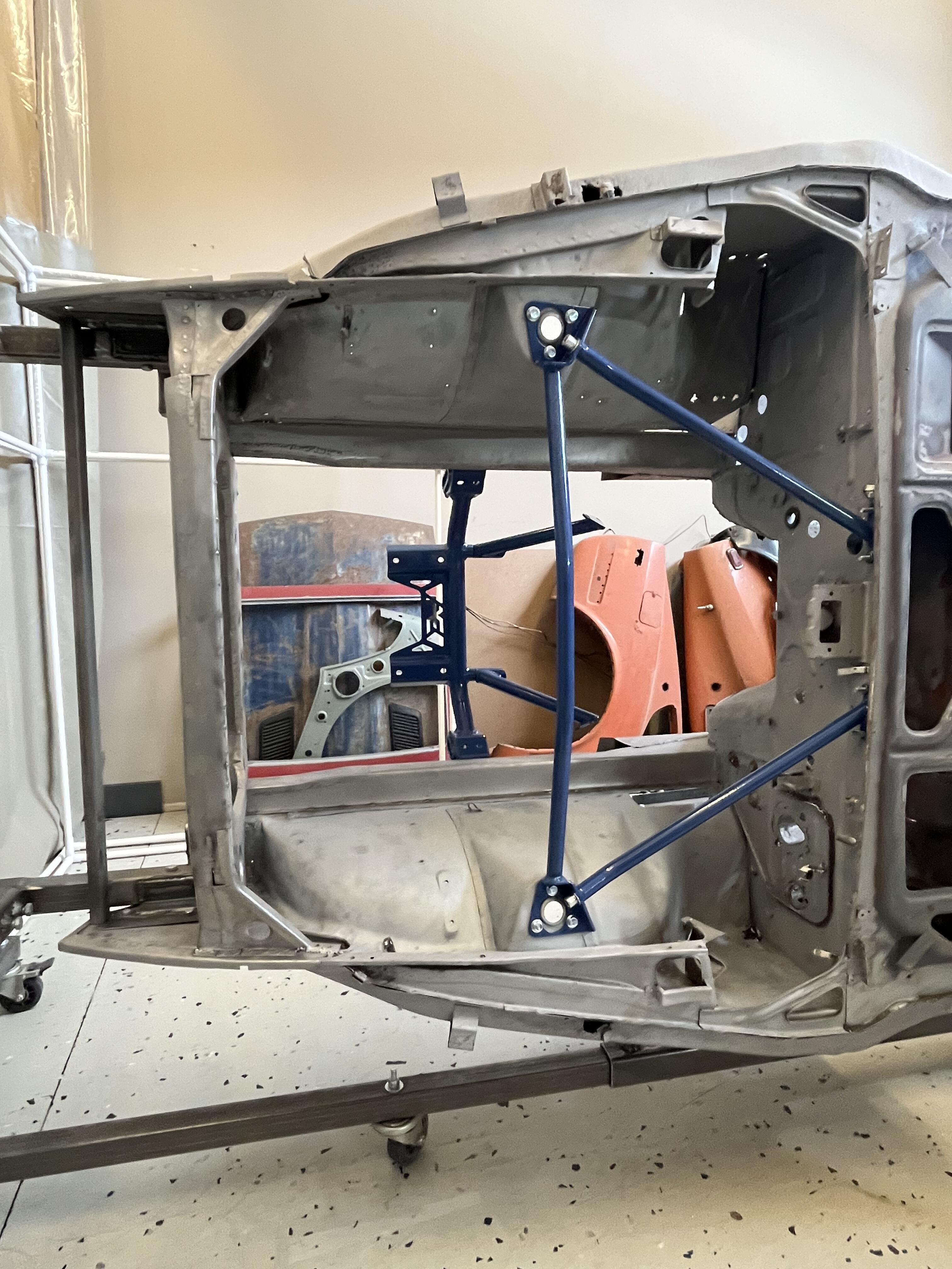
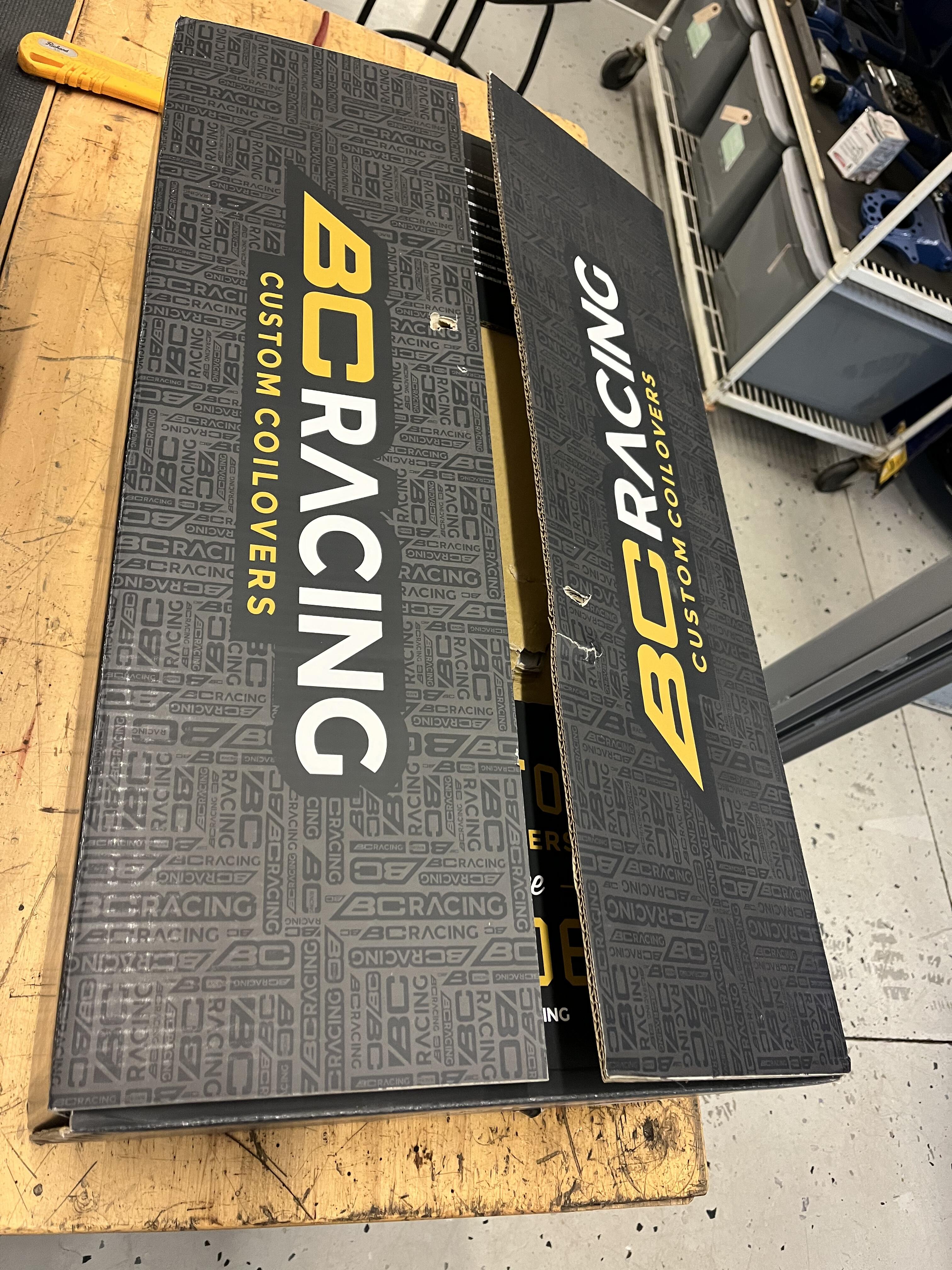
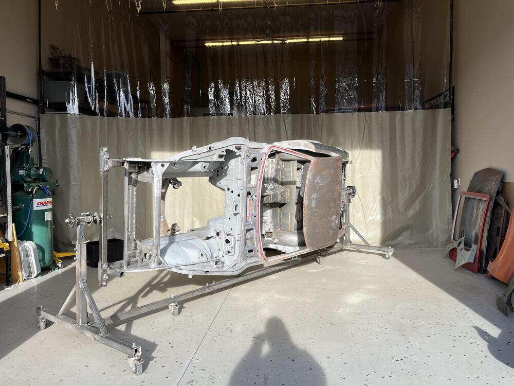
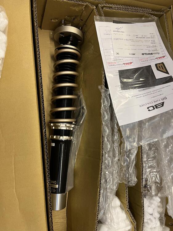
3 pointsWell... she's blasted and tent is disassembled ... now to finish the remaining rust repair and test fit everything. I hope to have a roller in March sometime... I did not try to blast the roof section. I'll be using the Eastwood Contour SCT instead when it's time ... It looks a lot better than I thought it would actually. Cleaned up nice !!! And started test fitting some of the ApexEngineered bits...Here are some teasers...Full review to follow... And last but not least...Black Friday BC Racing weld on coilovers showed up... right on time 😉


 3 points
 -
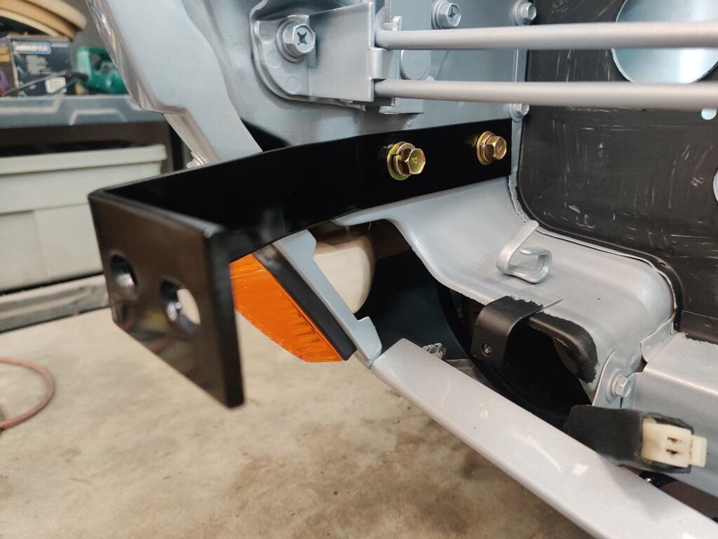
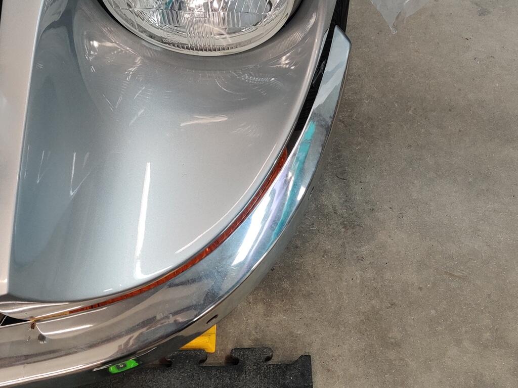
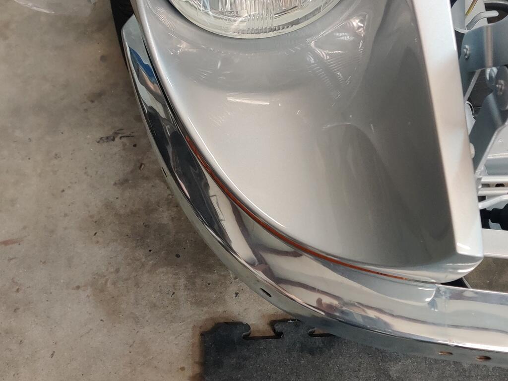
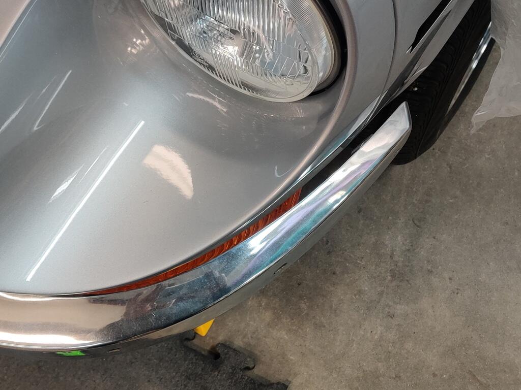
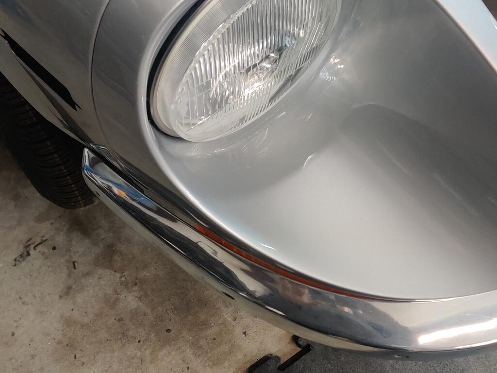
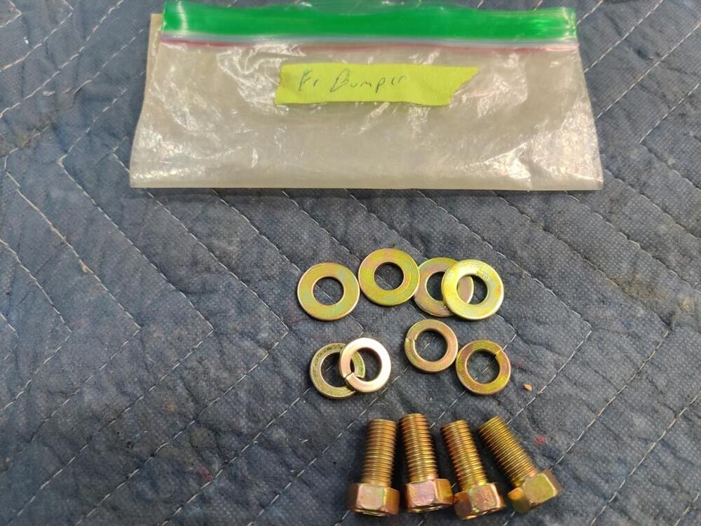
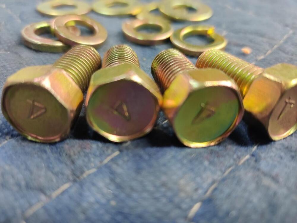
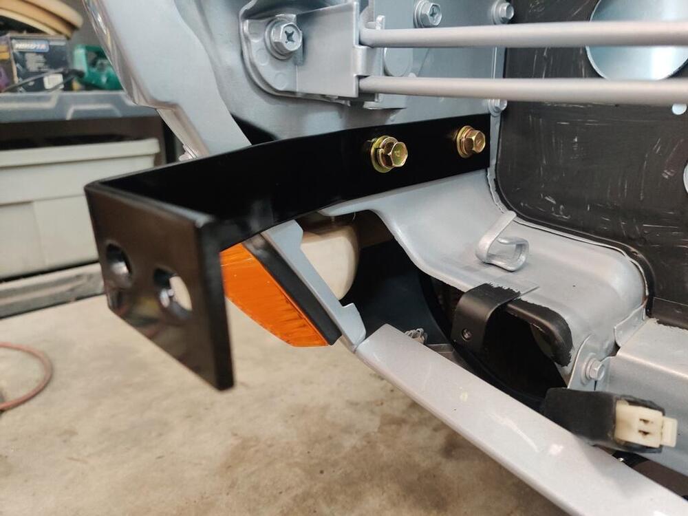
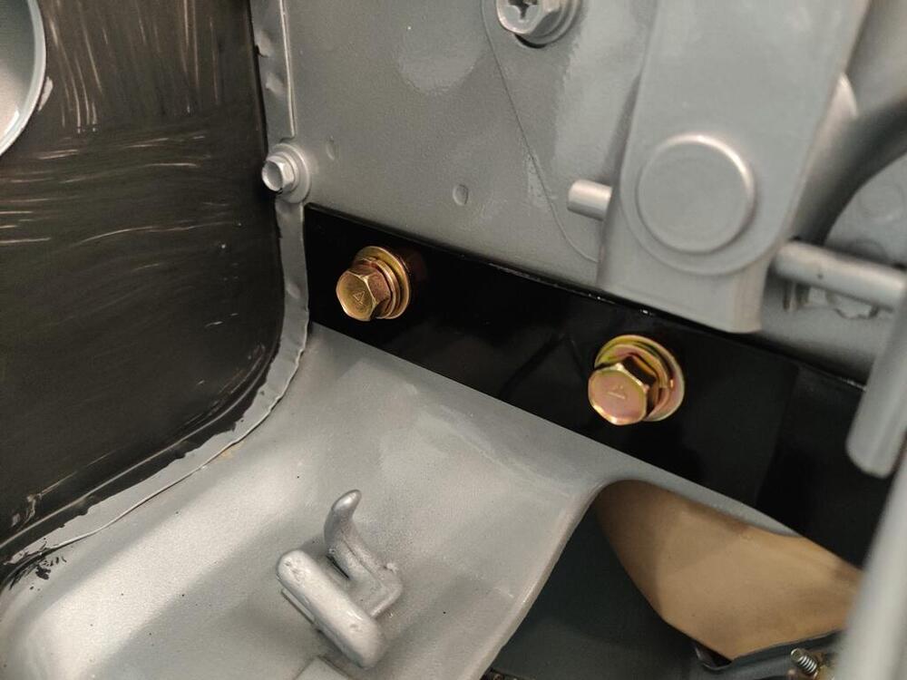
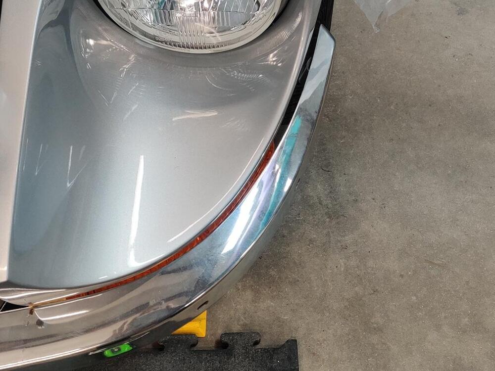
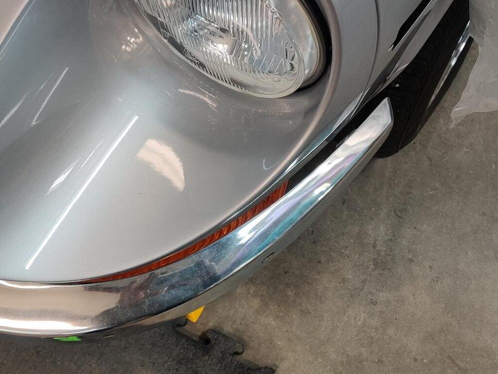
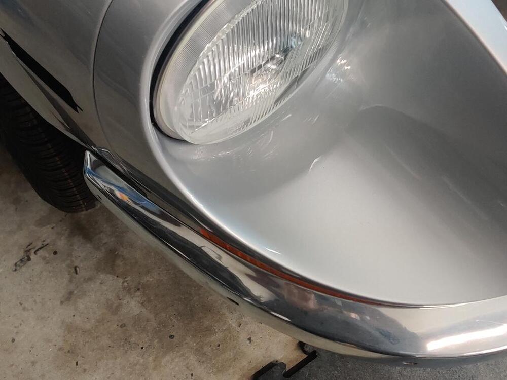
@dutchzcarguy - I measured 3.4 ohms of resistance. Yay! Tonight I put my focus on testing fit of the front bumper. I made note of asymmetric fit a long time ago and though I worked on it some to address that at the time, I want to resolve the issue completely before sending it off for re-chroming. While it looks pretty close, the bumper curve matches the curvature of the body on the the right side well and on the left side not as well. Those two picture show the difference pretty well. The curvature of the bumper on the left side of the bumper is less than the curvature of the body, causing the bumper end to stick out a bit. I double checked the left vs. right center alignment of the bumper. It is within an 1/8th of an inch of being centered. I checked the bumper mounting brackets for symmetry and that is good. So, I will see if I can work the left bumper end a bit to tighten the curve. I think it likely that the upper and lower surfaces on that end just need to spread a touch further apart. Doing that should tighten the arc. I also have been working on the original rear bumper. Pictures don't really capture what the issue is. This car was tapped in the rear, and the center bumper bar was "re-shaped" a bit during that impact. In this picture, a new old stock bumper is on the left and the original bumper on the right. If you look closely, you will see some of the rear "face" of the original bumper (on the right), especially in the center of the bumper bar. It also has less curvature over its length when comparing to the NOS bumper. When it was hit from behind the center of the bar was twisted... downward. I have been working it to restore its original shape using the NOS bumper as a guide. Generally, this involves using my hydraulic press and some pieces of scrap metal which I use to clamp the bumper in place. Then I beat on it with a hammer to attempt to reverse the "twist" it has. I also use the scrap metal as spacers, and use the press to push on certain areas to work curvature back into it. When looking at the picture above, I will be happy when I can get that rear face to not be visible at this same viewing angle. The curvature also needs to be restored to mirror the NOS bumper section on the left. Both the original bumpers are quite rust free, so I feel they are worth the time and effort to straighten. I also want to get the shape right before sending them to the plater. Then, they can focus on banging out the little dents, and grinding and straightening to remove the surface imperfections. I will be sending the original rear and the NOS rear bumper pieces, and two front bumpers, as well plus one set of over riders for the front and one for the rear.

 3 points
 -
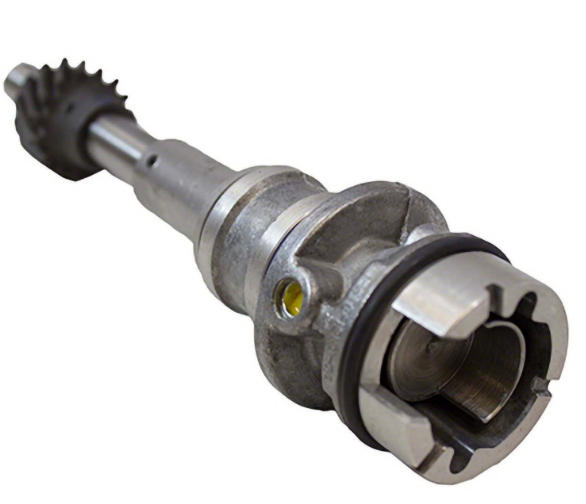
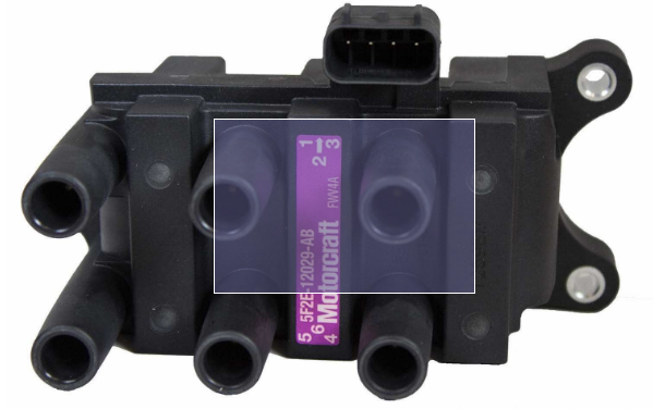
I haven't thought about the aftermarket stuff for a while but I know that on my 2003 Ford engine, the old distributor shaft remnant is used to indicate compression stroke of #1 to the PCM (computer) for sequential injection. That's all it does, it's not involved in precise timing at all. Ford basically cut the top off of a distributor and replaced it with a half moon trigger and a camshaft position sensor. The engine has a crank shaft trigger wheel for ignition timing. And it uses wasted spark. Wasted spark just sends spark to cylinders that are on either exhaust or compression strokes. Doesn't matter, the cylinder that needs it will get it. The other one won't even know. DIYAutotune has a bunch of tech articles and parts. Worth browsing. https://www.diyautotune.com/support/tech/ https://www.diyautotune.com/?s=nissan Ford stuff below. To think about. You can find a bunch on Hybridz and probably DIYAutotune about Ford's EDIS ignition. That's a common wasted spark system that people swap over to.
 2 points
 -
2 points
-
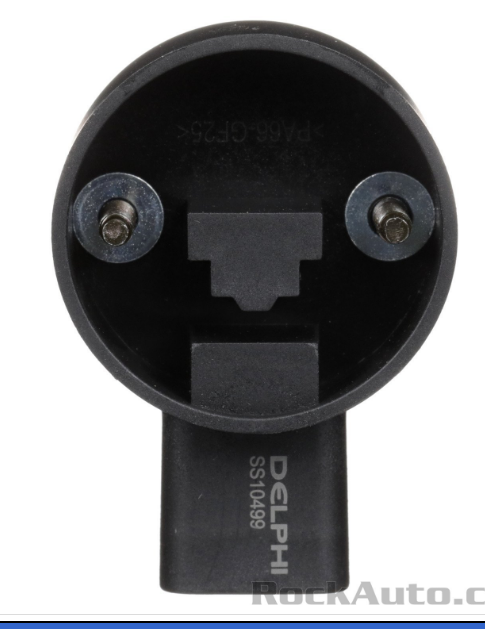
I was told by Rebello that there wasn't a HP benefit they saw from wasted spark to fully sequential, I honestly did it just because it wasn't hard. Cost me like 90$ for the jeep sensor mod, plus some wiring. A turbo dizzy can't do fully sequential. But can provide the ecu with enough info for wasted spark. I don't exactly know how the onesix unit does fully sequential, but I know it can. So it must provide 2 signals? Cam signal will have more "slop" in it, crank is superior for that. You can also use a flywheel trigger, but that is more rare. If you google or search for the jeep cas sensor mod, you will find info, I think either milkfab or bossa makes it so you can buy it already done. https://milkfab-engineering.com/shop/ols/products/milkfab-lseries-camshaft-position-sensor2 points
-
I'm not sure fully sequential is beneficial either. It does place less load on ignition components though. I would probably get a crank trigger and run wasted spark and move on. I would probably only visit fully sequential if I had a problem doing that. Some of the vendors might be able to give you more experienced feedback if you reach out to them. They have a vested interest in your success...2 points
-
2 points
-
2 points
-
1 point
-
1 point
-
@duffymahoney That helped me understand things so much better, led me off on a trail or more research, thank you. My biggest question is how does the 280zxet dizzy act as both a crank angle sensor and cam angle sensor. Because it does this, it may be simpler to just do this than to get a crank angle sensor on the harmonic balancer and then a cam angle sensor where the dizzy used to be. However, both options look very simple. I was wondering which Jeep cam angle sensor you used? I can't find a part number for it on other forums. Looks like a solid setup to be honest. How smoothly does ur fully sequential motor run? I think the mega squirt platform can handle wasted spark but I would have to look further into it. I think fully sequential would be kind of fun to do, and definitely more modern than doing batch fire and wasted spark setup. I know lots of cars use the wasted spark and batch fire just fine though. Wondering how many years this mega squirt system would last if done properly. I don't want to deal with any of the pain the OEM injection has put me through with constant maintenance and tuning/fixing.1 point
-
@dutchzcarguy @Patcon . I am very new in teaching myself how DIY fuel injection works, let alone the ignition system. I think you have convinced me to go coil on plug, and sequential injection though. I think the modern approach definitely is the approach, I just don't understand how to do COP without the 280zxet dizzy. Would something like this work?https://protunerz.com/collections/sensors/products/onesix-industries-l-series-crank-sensor-hall-billet-new From my understanding to do sequential injection you need something that can measure cam and crank position, and CAS is the way to do the crank? I think this little dingy is just a distributorless CAS. But then what measures the cam? Trying to get educated. The more I learn the easier and more complex it gets at the same time. @duffymahoney I pulled up the sight. How do I navigate it haha. I am not versed in Japanese lol.1 point
-
1 point
-
That is the one I got.1 point
-
1 point
-
1 pointGood luck! Will keep you in mind if I'm in the market for your wares.1 point
-
1 point
-
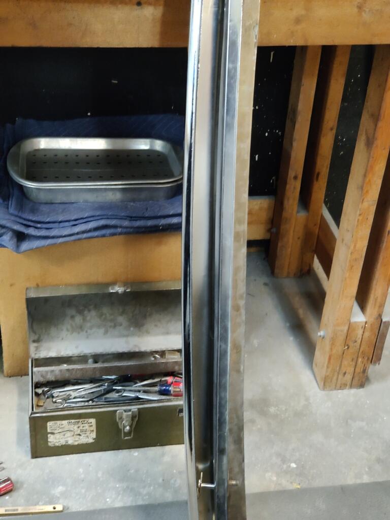
1 pointYes, "phenolic" is in the title but there is a lot more included in the correct product name because there are numerous different products that have "phenolic" in the material name. My current plastic choice is Torlon 5030 to replace primarily the circuit board in the hi-lo beam switch but it would be nice to maybe have the same material as OEM. On the other hand, that stuff was kind of too fragile to use as the hi- lo circuit board and 50 years on they are mostly broken or break when attempting removal from the switch housing. Thanks Jim1 point
-
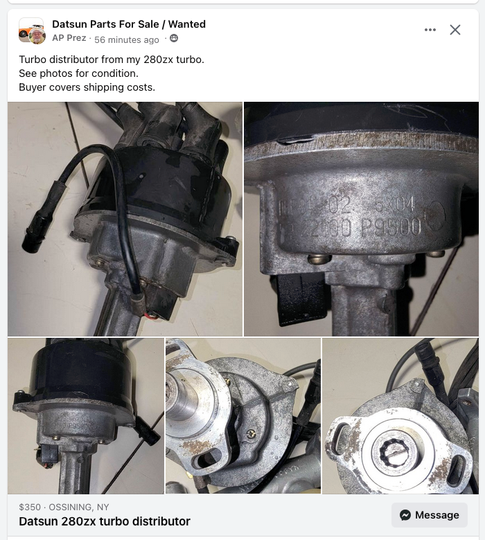
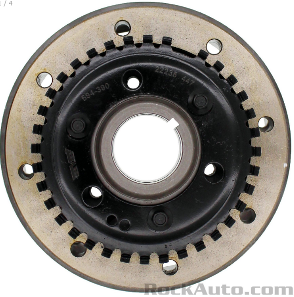
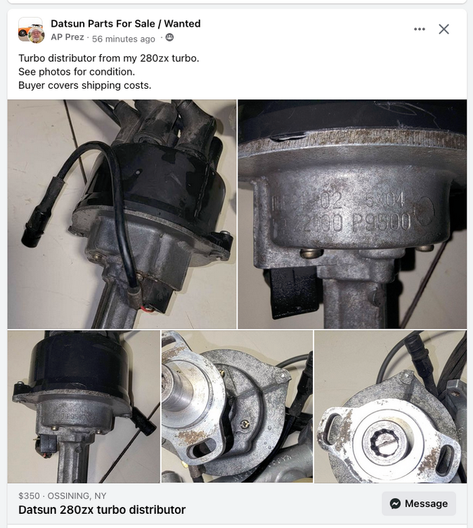
I saw this on Face Book. $350 seems a bit steep though.
 1 point
 -
1 pointYes, if I end up getting a 240mm flywheel, I’ll need to get the matching clutch and pressure plate. Unless I get the Fidanza, which is 240mm, but apparently can accommodate either a 240mm or 225mm clutch and pressure plate, which is cool. But before I drop $500 on a setup like that, I’m going to call a few shops and see if I can get my existing 225mm flywheel resurfaced and lightened. Will prolly be significantly cheaper than an aluminum flywheel, and add some performance gains. Then I’ll just pair it with a decent (exedy maybe) clutch/pressure plate, and then go through the whole process of making sure I have the correct SLEEVE, ugh. This is prolly my best bang for the buck to eek out some performance gains, using quality parts, without breaking the bank. The trifecta! We’ll see if I can make it happen… Sent from my iPhone using Tapatalk1 point
-
Thank you - I'll make a sketch with accurate measurements of the span & PM you. It may only be a 10' opening.1 point
-
I forgot to mention that I spray Windex on the body of the car before putting the quarter windows in place. It lubricates the area so the rubber doesn't fight your attempts to compress it as much.1 point
-
1 pointBasically hand blocks, a combination hard foam Durablocks and home made hard acrylic blocks, 80 grit up to 600 for the primers then 1200 to 2500 for the clear coat. The first sanding of the clear coat with all of the orange peel I use DA sander and 6" disc 1200 grit to get the worst of the rough surface off then 1200 with a hand block to flatten it out. Then hand block for the rest of the grits down to 2500. 80 to 400 grit is all done with dry paper, 600 to 2500 is done wet using a squirt bottle and a bucket of water. I use a combination of loose paper and adhesive backed roll paper, I don't buy the most expensive 3M paper because there are a many companies that make equally good quality paper that cost a lot less. Any collision shop would laugh at my procedure as they do almost all their work with air sanders, I could do that too but it is very easy to screw up quickly doing it that way and I don't get enough practice to get good at it. By hand is slow and hard but much easier to control.


 1 point
 -
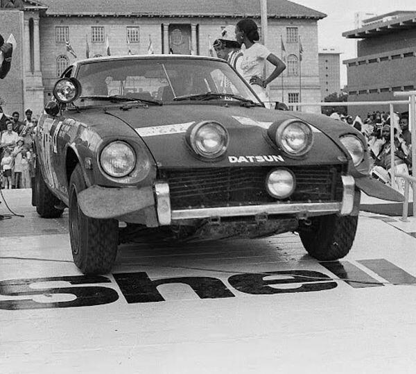
At speed, it would act something like a surfboard. I think there's a skill to driving through deep standing water where you create a sort of 'bow wave' effect which pushes the water out in front of the car at the right speed to stop it coming over the top of the car? Some of the later cars had big rubber flaps attached to the corners of the front bumper to help with this.
 1 point
 -
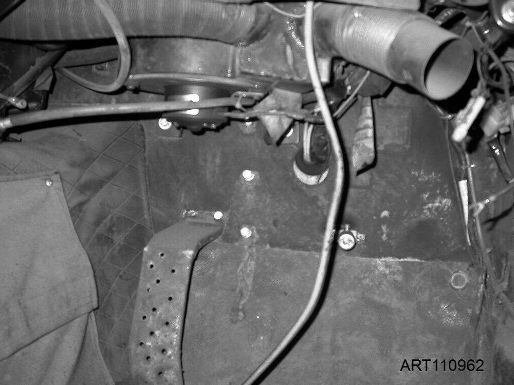
Hi Kats, What was the date of the interview? I don't believe there was anything like that on the Works cars before 1972, and I honestly don't ever recall seeing anything of that nature in *any* of the Works 240Zs. It's hard to imagine how such a system could operate without big changes to the structure of the car, especially in the cowl and firewall area, and any ducting joining the cabin to the carbs or injection would easily be visible in the engine bay. Never seen anything like that. I wonder if it might be a case of misunderstanding between Namba san, Wakabayashi san and the journalist involved? The only thing I can think of is the modified cabin blower system used on the 1972 RAC Rally and 1973 Safari Rally cars, which was fundamentally different than the stock item. They turned the uprated fan and motor through 90 degrees and added some huge filters and ducts to the system. On the Safari Rally - if the weather was dry - they had huge problems with 'Murram', the fine red dust that forms many of the road surfaces on the route. It got everywhere, clogging up instrumentation and mechanisms. I should imagine the modified ventilation system was part of dealing with that. It's not a very good shot, but here's my view from the passenger seat of '7924', the 1973 East African Safari Rally-winning car (Shekhar Mehta/'Lofty' Drews) which had previously used by Rauno Aaltonen on the 1972 RAC Rally. You can see the 'clocked' fan and housing and some of the big ducting that was part of the system:
 1 point
 -
1 pointThe intake is about the same length as a harada (about 2mm shorter) the jenvy one is longer and so is the cannon. It's all a give and take. My next intake design will be longer, shorter throttle bodies, injectors mid runner.1 point