All Activity
- Today
-
 You can't see the text that accompanied the photo? Here it is again:
 -
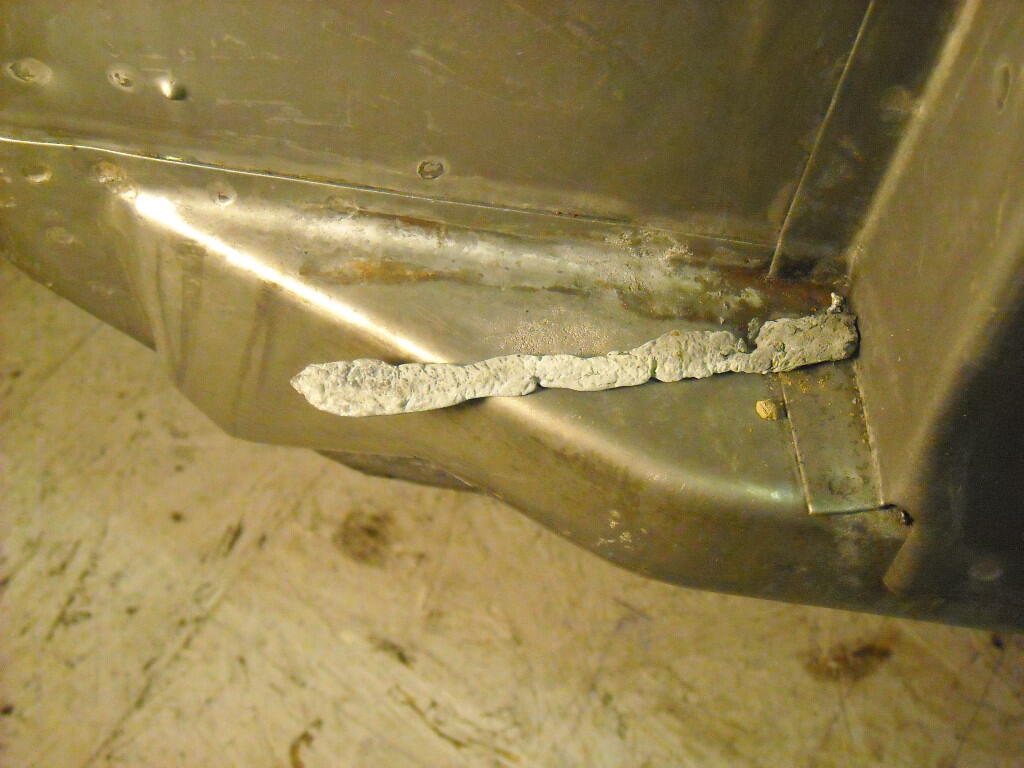
 Those are rust stains from the rinse water draining off, I've never found any braze that looked like it came from the factory.
 -
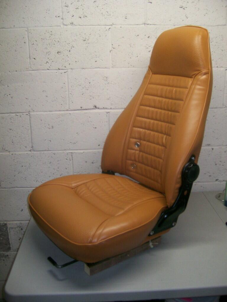
Nice job. I used Distinctive Industries' covers when re-doing the seats for my 70 Z. I did not purchase new foam b/c the OE foam still seemed in good shape. Long story short, I found the fit of the new covers to be a bit baggy. Things improved a lot with the addition of 1/2" and 1/4" foam sheet in strategic locations (esp. the front and side bolsters), along with pushed-into-place 'basting' material (bought at a dressmaker's shop) that helped to remove/reduce wrinkles in certain locations. I was pretty happy with the end result, esp. considering the fact that this was my first-ever venture into the world of automotive upholstery. FWIW, hot rod and boat shops can provide a lot of guidance for this type of work.

-
 Excellent photos. Thanks for posting. It is, indeed, a complicated joint. I'm always impressed by the skills of the manufacturing engineers and designers who (with little credit) develop such schemes and make them ready for mass-production. I've often wished for 'exploded view' explanations of how the contributing panels come together at complex joints such as this one (another good example is the 'dogleg' behind the lower-rear door area). Unfortunately, it would require either: a) an informed industrial artist (similar to the person who created the drawings in the parts manual), or; b) a photographer in possession of all of the individual panels/stampings. Alas, the chances of either happening is remote.
 -
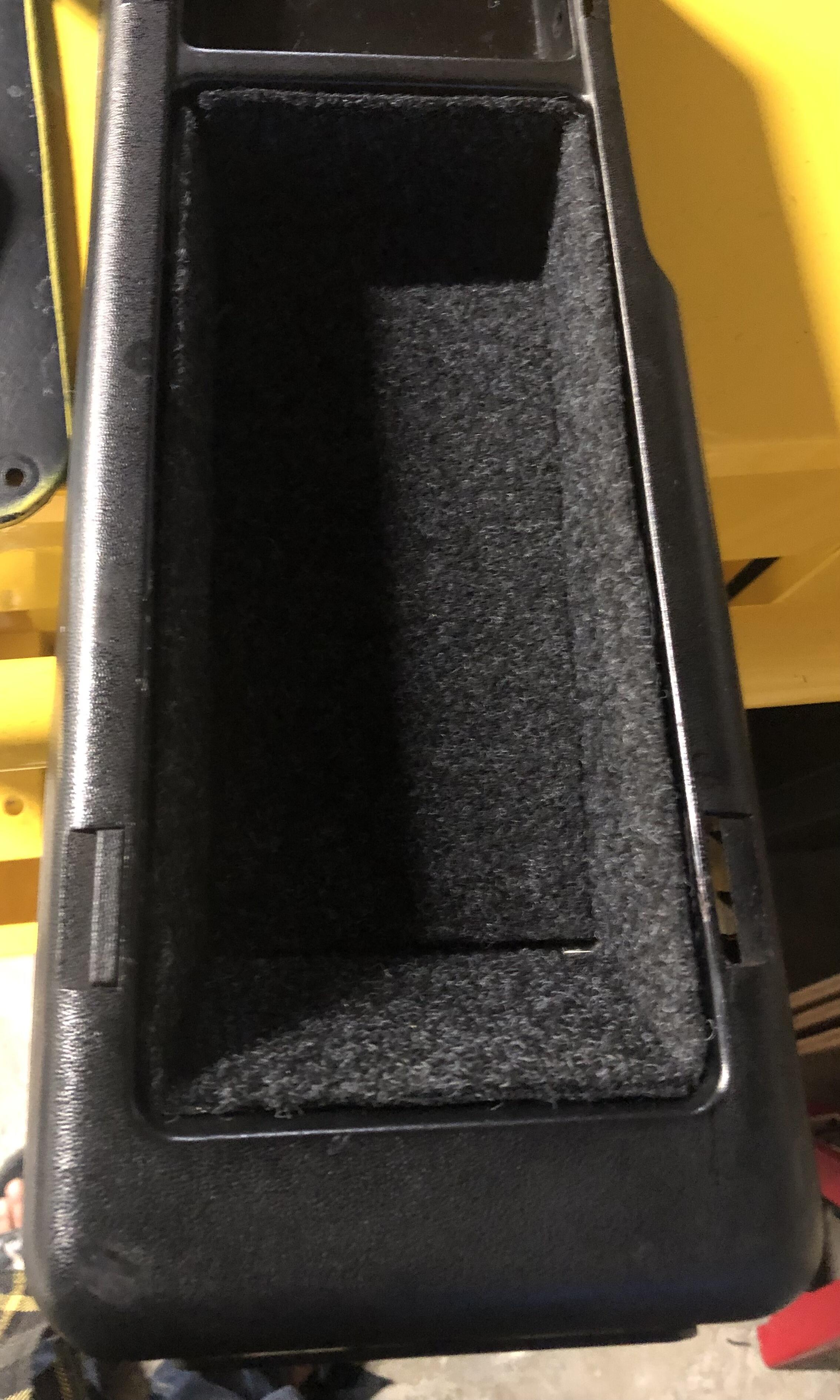
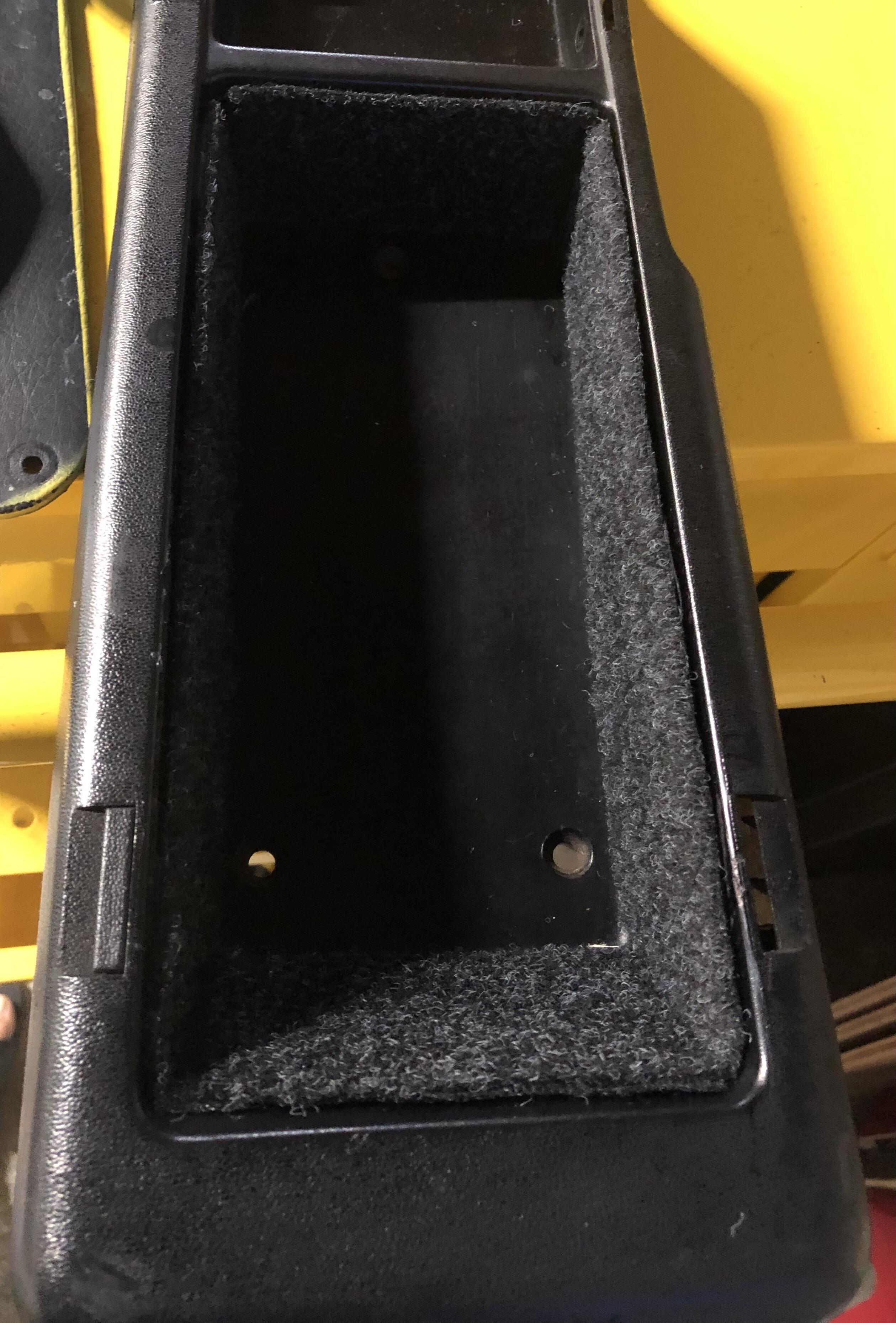
Calling it a day. Seam sealer was good enough for some cosmetic adjustments. Felt is attached with double sided tape.
-
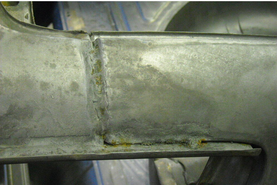
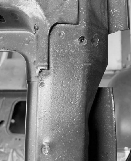
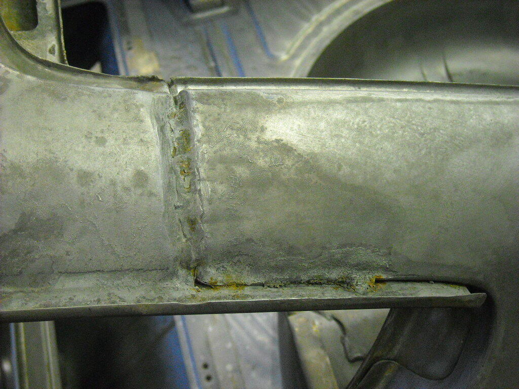
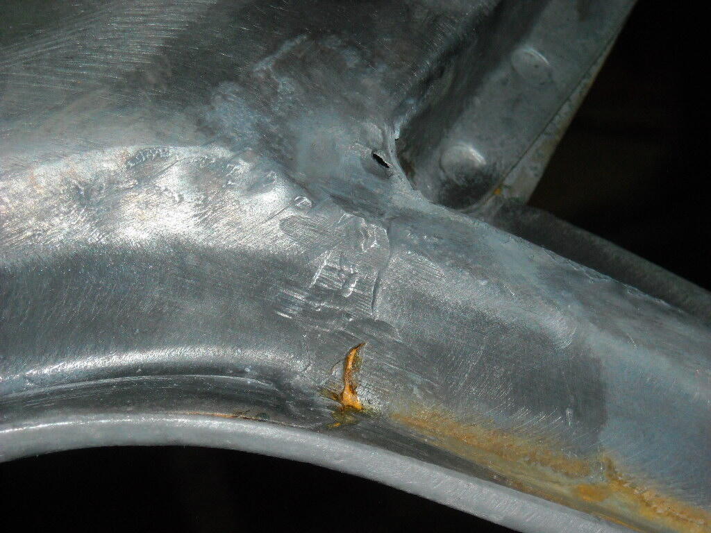
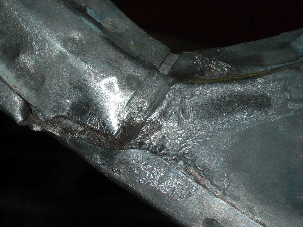
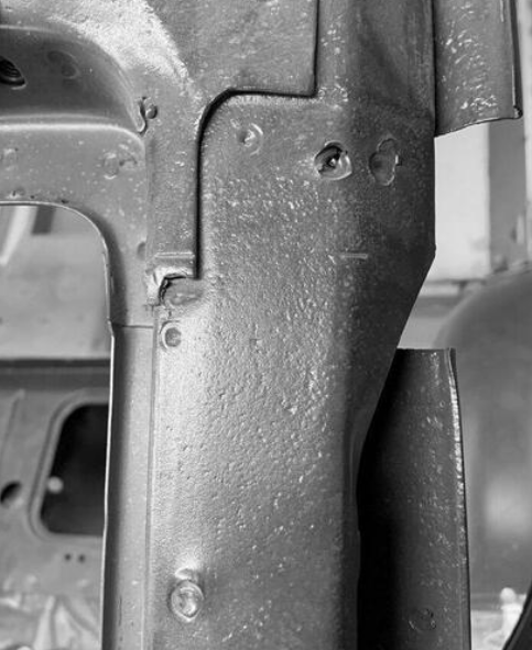
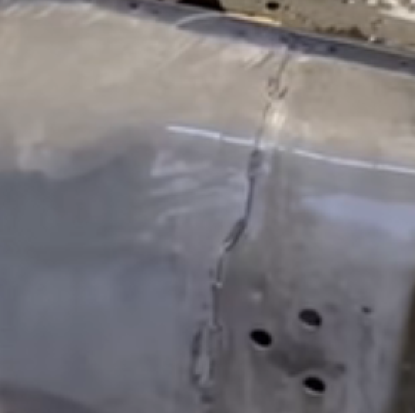
 That's two pictures of the C pillar seam area now. The first one was the inside of the bottom half of the pillar, yours is the top part that gets treated with lead. It seems like what yours shows is that the the outer/upper portion of the seam is welded, then covered with lead to fill the groove left behind. Those blobs are probably welds. So, both spot welds and seam welds are used to create the pillar. A messy area to work on, as you said. Hard to see how you'd get it apart without creating a lot of extra work. You can see how the upper part of the "tube" that you show sits on the lower part that was shown earlier. And there's rust on the weld blobs. It might be crude brazing efforts. Not an expert on welding methods, older or newer.
-
OK - I typically replace line clamps with Oetiker clamps for anything that doesn't require routine service.
-
Yeah, the hose clamps. I changed the original clamps to a more modern style gates/belt clamp because you can get more clampage out of them
-
apologies - I didn't see the question - yes, that is what I would do there. EDIT - actually I think you would add a vacuum line. The ports are listed PCV - Carb - Tank, so I think all three would be used. I'd look at a GM schematic for the model it's intended for. When you say belt clamps, you mean the hose clamps?
-
Update: I took the entire vapor system apart and pressure tested each hose and the vapor tank by blowing into one inlet and capping the others with my hands; didn't taste great. The result was finding all of the hoses and the tank hold air perfectly. I put everything back together and when blowing from the front could still smell gas in the back. I threw caution to the wind and cranked the belt clamps down to within an inch of their life and problem solved - no fumes. Crank those clamps down boys and girls - case closed
-
Found them, not sure these are going to help much, seems like only some of the lead melted off. 1st pic is melted lead that had pooled,
- Yesterday
-
Sorry, I didn't recognize it. It would be nice to know if that picture is from a production car or somewhere else. There's no identifying text for that shot. Here it is, from post #89. More detail would be helpful. How much overlap is there in the joint? What does the backside look like? A good old rusty production car joint would be good to see.
-
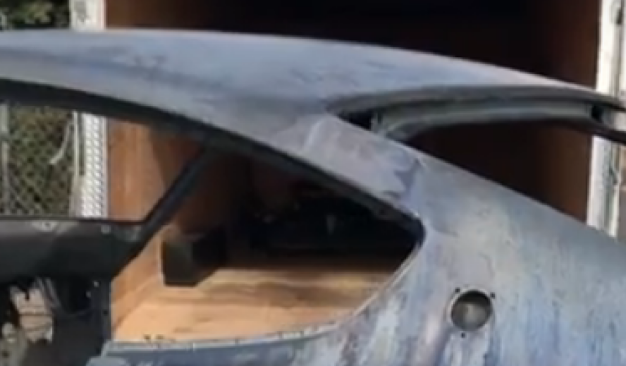
 I have seen pictures of the qtr to roof joint over the years. There have also been pictures posted up of roof cuts that show how many layers are in this area. I don't remember what threads they were in. It is a very complicated joint with multiple layers
 -
You obviously don't see the drilled-out spotwelds either.
-
No I don't recall that part of the conversation.
-
I was talking about the C pillar. The original joint of concern, and the start of the lead focus. I don't see a lead-free but intact C pillar joint in anybody's pictures.
-
Posts nos. 88 & 89 in this thread answer those questions, I'd say.
-
Watered Rodger, the 240. He has a new friend, Archie. Can't wait to shake brakes with one another.
-
The remaining question seems to be - what is under the lead? grannyknot has seen it, apparently. I think that most people are just used to seeing the lead filler and don't think about what's under it. I'd guess it's more stitch welds but it might be spot. Hope he finds those pictures. Maybe he remembers and can describe more. You should be able to melt the lead out and grind the welds down to open it up but you'd probably have to do more than one seam since any flexibility will be of low magnitude. Could be a can of worms.
-
 It’s all good, I am reading through and trying to learn as well, soak in what I can, I’m hoping to not have to pull apart the flexiflier joint, but will if needed. The conversation is directly related to this build and others.
 -
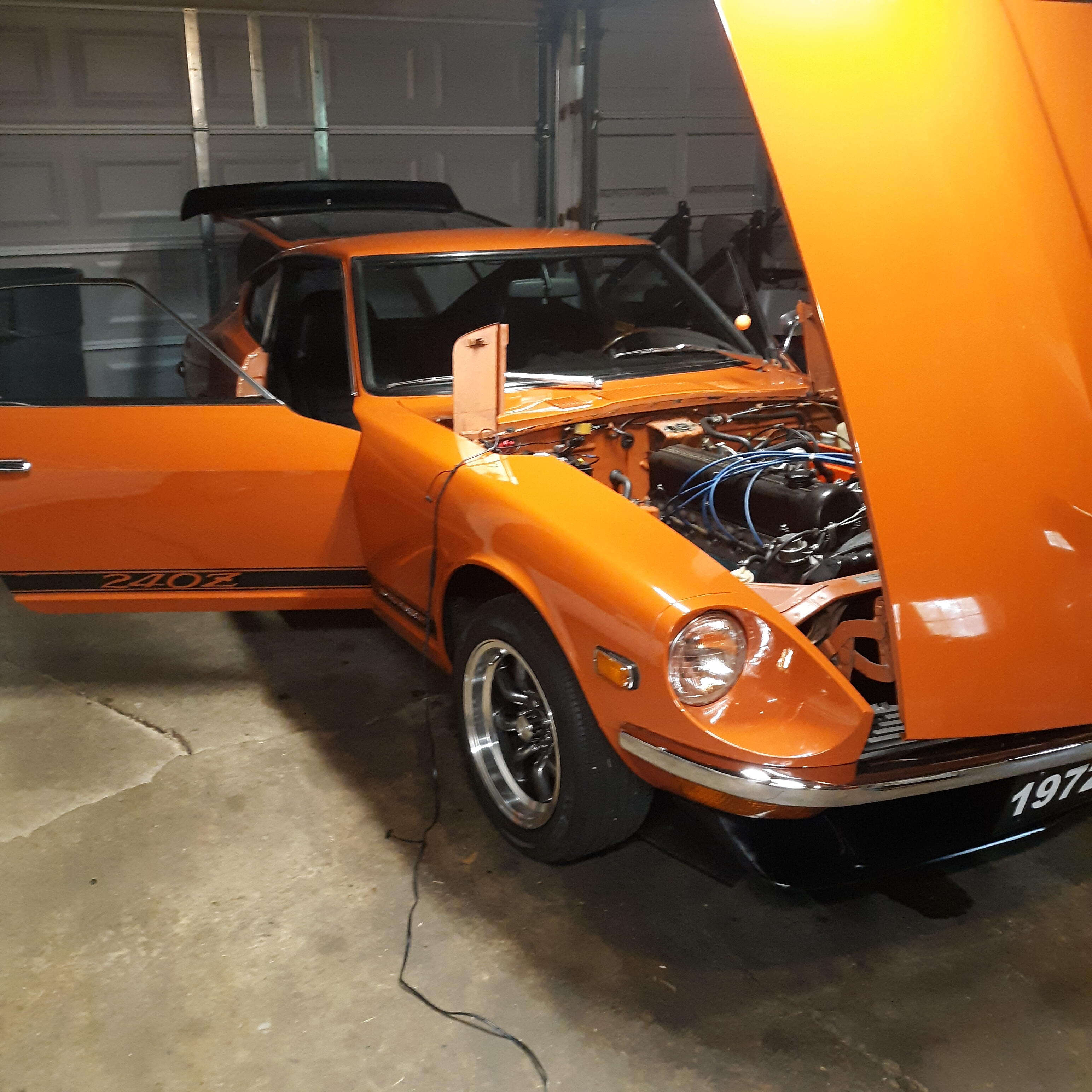
 Wait... I know. You're HOT, right??!
 -
 Check your fuses if you haven't already.
 -
dspillman, if you want to refocus on your restore goal just say so. This is an interesting aside though. I found a 77 seam. It doesn't look much better than the 240Z's. Maybe a little bit smoother. Still just a fairly crude stitch weld. https://youtu.be/uN8ca_KFVcw?feature=shared&t=415
-
 I've never had a good look at that seam but I vaguely remember Matsuo-San talking about the welded seam options. Butt or flush lap seams would be too stiff so they opted to bend both sides 90 degrees (or possibly a standing seam joint) to join the two parts. @Patcon Charles, do you remember that part of the conversation?
 -
I've used a insulation piercing volt meter many times without removing the part I was testing voltage on. It has a needle like end you push through the outer insulation to the copper wire for testing. I can't say how many times I've pricked my fingers to accidentally test MY voltage.