.JPG.cfcada9cf1c1b502df3f5f2f2ca3ff36.JPG)

SteveJ
Community Member
-
Joined
-
Last visited
Everything posted by SteveJ
-
If it's shorted, no voltage will pass. Since the gauges move on decreased resistance, they would be pegged if there was a short.
-
You can always just see if you have voltage to ground at the end of the wires in the engine bay and at the fuel tank. No voltage = no signal.
-
Of course, it wouldn't hurt to see if you're getting voltage at the dash to engine harness connector for the water temp and oil pressure and at the dash to body for the fuel gauge. See page BE-34 for the water temp & oil pressure wiring. See page BE-35 for the fuel gauge.
-
You could use potentiometers: https://www.amazon.com/TWTADE-Potentiometer-Single-Variable-Aluminum/dp/B07DHGHQPQ Then you would also see gauge response. Center tap to ground and signal on CW or CCW.
-
Ejection seat
-
I've spent WAY too much time on Amazon studying generic door seals for the 240Z. I even tried some with mixed results. The first one I tried had a "bulb" of 3/8 of an inch (9.5mm). It left gaps, allowing wind noise. I took a chance and went big on the next try with a 0.7 inch bulb (17.8mm). The door would not close properly. Okay, so I figured the "mama bear" size would be about 0.5 inch (12.7mm). I got it today and installed it. It had a nice snug fit around the doorway. The door takes a fair amount of effort to close, but it will close completely. There are no gaps that I can find around the door, either. Here's a link to this door seal on Amazon: https://www.amazon.com/dp/B097MPM512 20220220_164404.mp4 Now to get more for the passenger side. By the way, you'll need about 11 feet of material to go all of the way around the door.
-
Exactly. That's why I asked for pictures with the cover off and the wires.
-
It will be a while before I can compile a list for you. I have a car coming over today for me to work on. Meanwhile please take photos of the VR with the cover off. Try to frame some of the photos where I can see the internals and the wires coming down to the connector.
-
There shouldn't be any parts that fall out if the VR is in good condition. However, it might be better to document the pin arrangements (wire colors) on both the engine harness and VR first. Something might jump out to us. Basically it's like the alternator isn't receiving the field signal from the VR recently installed. I would have to dig into to the circuit again to postulate the causes. What I would really like to see prior to tearing into things are some voltage measurements at the battery prior to starting and at 2500 RPM.
-
I believe @HappyZ is intending upon running a Pertronix or some other electronic ignition that can be retro-fitted into a 240Z distributor. Yes, you can put the 240Z distributor on the L28. And as for heat rise, I fabricated my own heat shield for my setup with an L28 with a Maxima head. I also have square port headers on it that I've been running for 5 years. I don't know if the engine is losing low end power. It pulls well.
-
Don't trust the gauge in the dash for good diagnostics. Get a real voltmeter for that. The gauge is good for "Oh crap, there's a problem" kind of readings. You know for sure there were issues with the old voltage regulator, just from the potting material being cracked. That could have allowed corrosion on the underside of the circuit board. Pro tip: You can use a sewing pin or a T-pin (office supply stores) to back-probe a connector like on the voltage regulator to see if it has the right signals. Let me know if you get a hand-held voltmeter, and I can walk you though taking measurements.
-
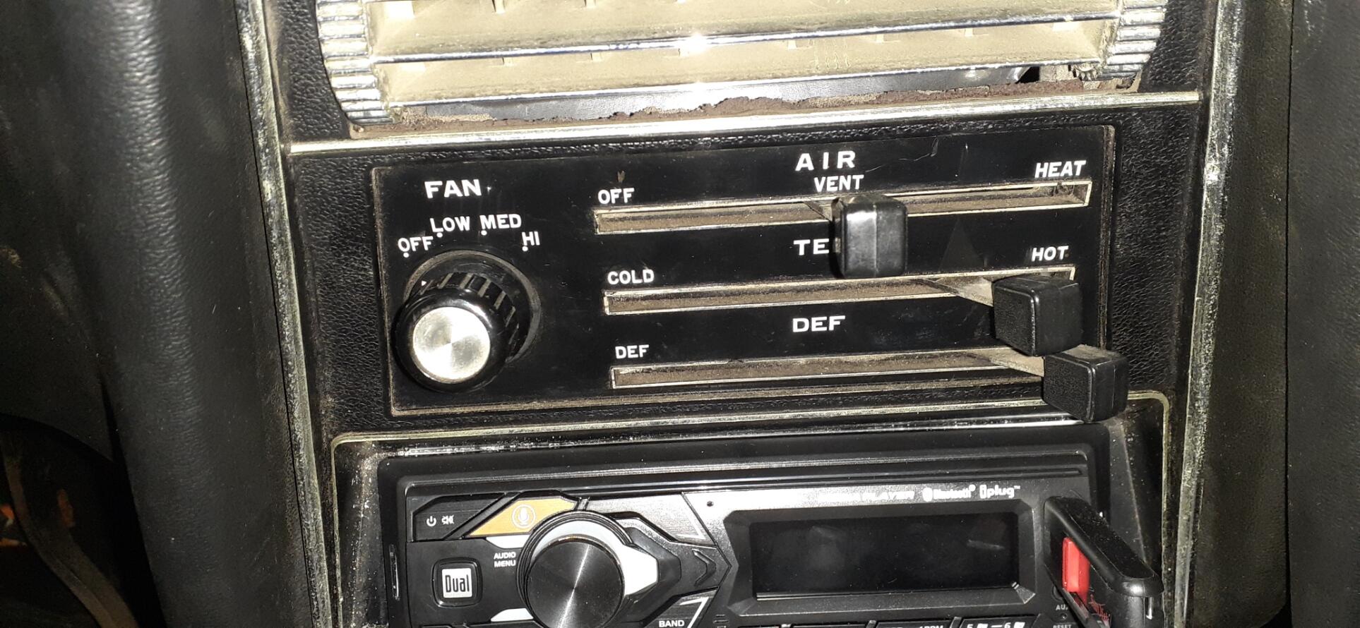
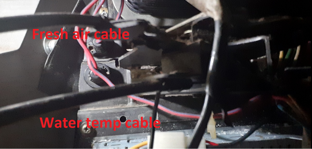
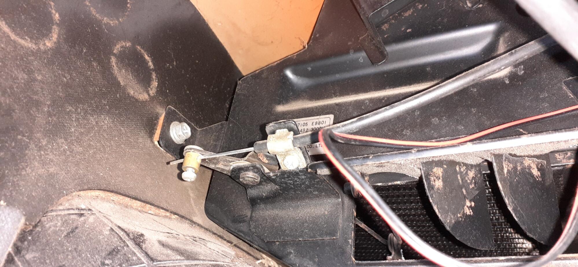
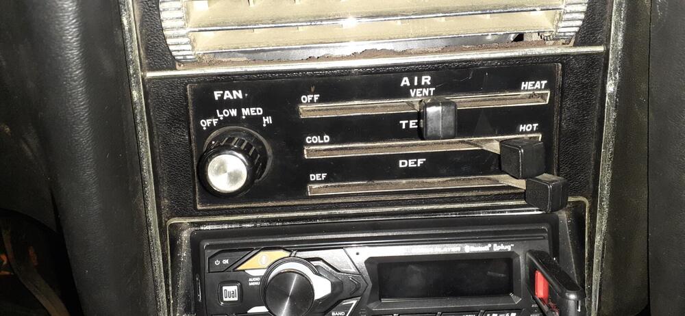
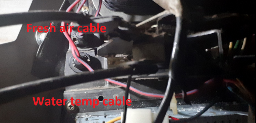
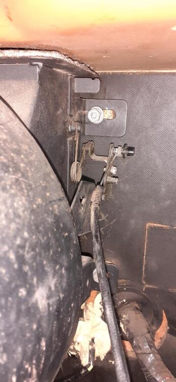
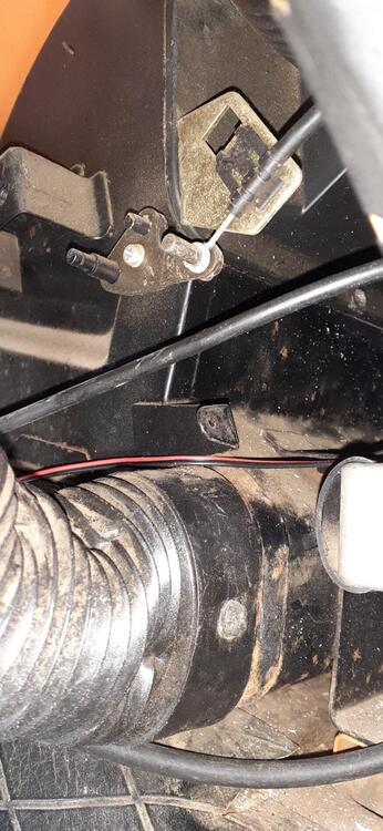
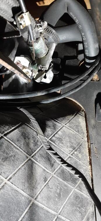
So there are 3 control levers with 4 control cables. The top lever has two cables. One of the cables goes off to the right. It moves when moving the top lever between Off and Vent. The other cable goes off to the left and moves when moving the lever between Vent and Heat. The middle lever for the temperature control goes to the right and connects at the watercock at the heater core. The bottom lever goes over to the left and connects near the door that covers the footwell vent. It moves when you move the lever from Def to Heat. Here's a backside view of the control panel. Sorry I couldn't get a better photo. At least you can see a couple of the cables. Here is the fresh air (Off to Vent) connection. It's up near the firewall in back of the fan box and is probably obscured by the glove box. (I removed the glove box recently.) Here is the Vent to Heat actuator. It is on the drivers side above the hose that goes to the side vent. Here is the cable connection at the watercock. It is on the passenger side near where the heater hoses come through the fire wall. Finally, here is the cable connection for the Def to Heat lever. It is on the driver's side near the firewall where the door for the heated air vent is. Does this give you what you were looking for?

-
Dang it! That's another tool added to my Amazon wish list.
-
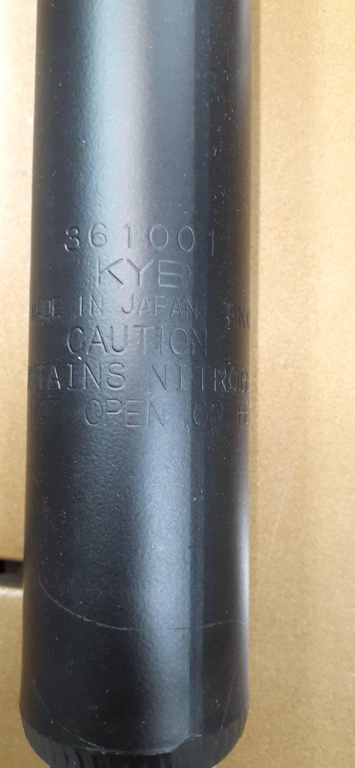
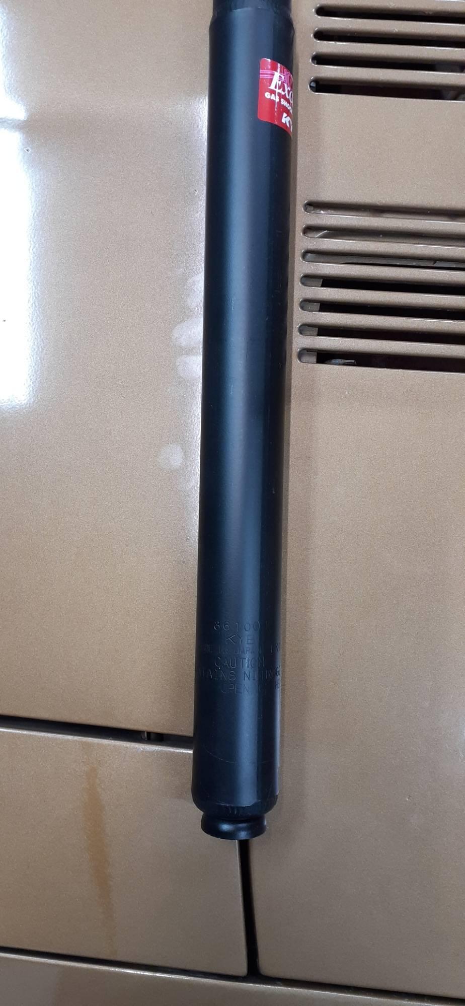
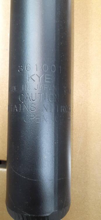
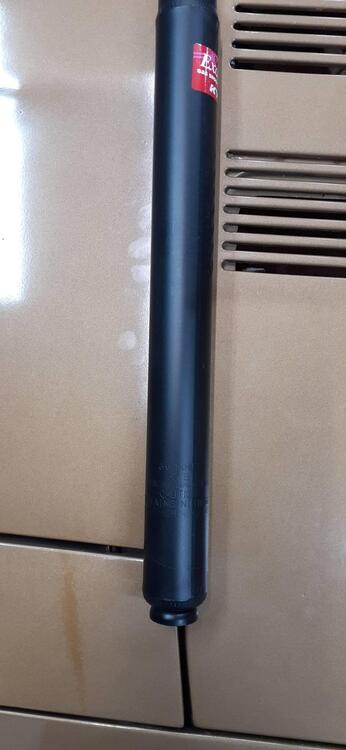
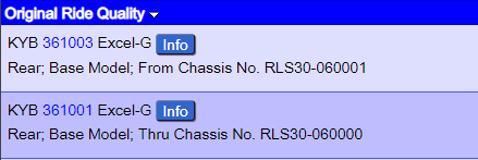
Yes, @Captain Obvious, the strut number is stamped on the housing toward the bottom.
-
This is why we need orange as a choice for paint. Also, I like the break in the grille.
-
That's what @240260280 taught me to do.
-
Here's my 2¢. First, make sure your valve lash is set properly. Second, make sure your ignition is set properly: timing, points gap, dwell, spark plug gaps. THEN you can set up the carburetors. I bring this up based upon the other thread where I talked about setting the dwell. Points that are not gapped properly or having too much or too little dwell time will result in poor spark. If the hydrocarbons are not being combusted during the spark, they would probably show up as a rich mixture with colortune. You may want to settle upon what you want to do about the electronic ignition before you use up all of your colortune supplies.
-
FYI - This is a screen snip from Rockauto's website. I know I had a noise one time when I didn't tighten the links properly on the sway bar. I haven't tried to see if this is possible, but could the sway bar be mounted upside down? Would it matter? Sorry, I won't have time to put my 260Z in the air until the weekend. Another possibility - Go through the RA section of the 74 FSM. See what it says about tightening some bolts. If one was tightened in the air when it should have been tightened on the ground, it could be binding. Were the new bushings rubber or poly? If poly, were they greased before install? Just spit-balling some. I hope it gives you some inspiration. While my springs aren't stock, the rest of the rear suspension is. Are there any photos I could take under the car to help you?
-
Keep in mind that manuals like that were probably drawn by draftsmen, not the engineers and technicians who worked on the cars. The engineers probably had to review in a rush and approve for publication so Nissan could make the microfiche, print manuals, and get all of the materials out to the supply chain and dealerships. It is almost without fail that I go back to drawings I approved years before and see some detail I got wrong. Keep that in mind as you look through the FSMs and other manuals. There could be an error lurking, but for the most part, the manuals are correct.
-
He turns 80 today. Walking the track to help visualize his line.
-
If you're tuning with points, do you have a good dwell meter? I once tried 3 dwell meters on one car and got 3 different readings. (To make it even more fun, the distributor was missing one of the adjustment screws, so I had to wing it while adjusting it.) I since got a 4th dwell meter so I could confuse myself more. The old school dwell meters are NLA. I might eventually break down and buy a Fluke 88V. I think it will measure dwell, and I only have about 8 or 9 multimeters, so there is a need to buy another meter. Once you switch over to an electronic ignition, you can probably retire the dwell meter. Sometimes I still work on a luddite's car, though, so I'm keeping them around.
-
That's only because you weren't around in the early days for ZMeFly. He scammed people, had his girlfriend post that he had died, and then scammed her. She came back to this site and told the truth. If you're wondering why the recent thread was deleted, read Mike's last post in this thread.
-
@jfa.series1 Do you have any front turn signals left?
-
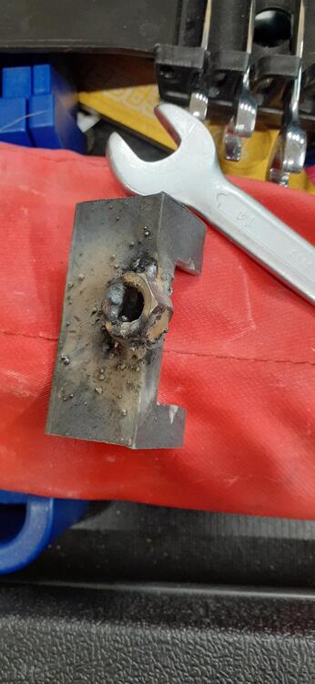
Redneck Lock Ring Tool - 2.5 inches of 1 inch angle iron. Cut a notch for posts on the sending unit, and weld a nut on there (with a better welder than I possess). I am curious, though, I looked through the 73 FSM, and I didn't see anything about installing the fuel sending unit. What exactly were you looking at? What section of the FSM?
-
Before you know it, it will be cheaper just to put on TBIs and Megasquirt.