.JPG.cfcada9cf1c1b502df3f5f2f2ca3ff36.JPG)

SteveJ
Free Member
-
Joined
-
Last visited
Everything posted by SteveJ
-
 When I searched ebay for the iBooster, I actually looked more at the Hondas because I don't think they have the booster mounted at an angle like the Tesla. I'm still not sure about what reservoir would be best to use in this application.
 -
An ammeter can fail, but that would also cause the car not to run. Bad wires at the ammeter would also cause the car not to run.
-
The ammeter doesn't really have good resolution, especially the ones that range from -60 to +60. Also I have no idea whether or not the one on @70z4fun's car has been zeroed out properly. Also consider the first test in the FSM for the alternator is to check the voltage. Why not make it easy and use a digital meter in the car? Also, one other thing I just remembered. Sometimes people add additional electrical loads to a Z and connect on the battery side of the ammeter. That could give a false indication of a failing alternator.
-
You could buy a cigarette lighter USB adapter like this: https://www.amazon.com/dp/B0C9DLDN19 It has a built in voltmeter. If you see it dropping below 13VDC while driving, you have a good clue that the alternator isn't putting out current or your battery is going bad.
-
Are you talking about the white and white/red wires at the fuse box? They branch off the wires going to the ammeter. I suggest not speculating too much. You will confuse yourself. Don't throw parts at problems. Diagnose.
-
FYI, I diagnosed a bad EFI relay on a 77 and told the owner to get the relay that @EuroDat said to buy. He got that relay, slapped it in, and the car ran just fine.
-
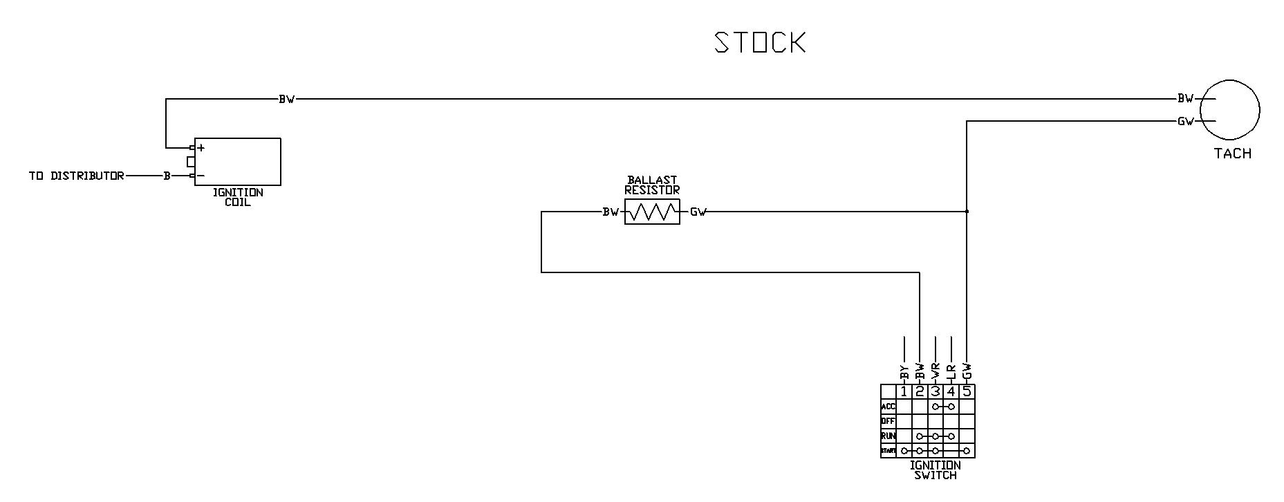
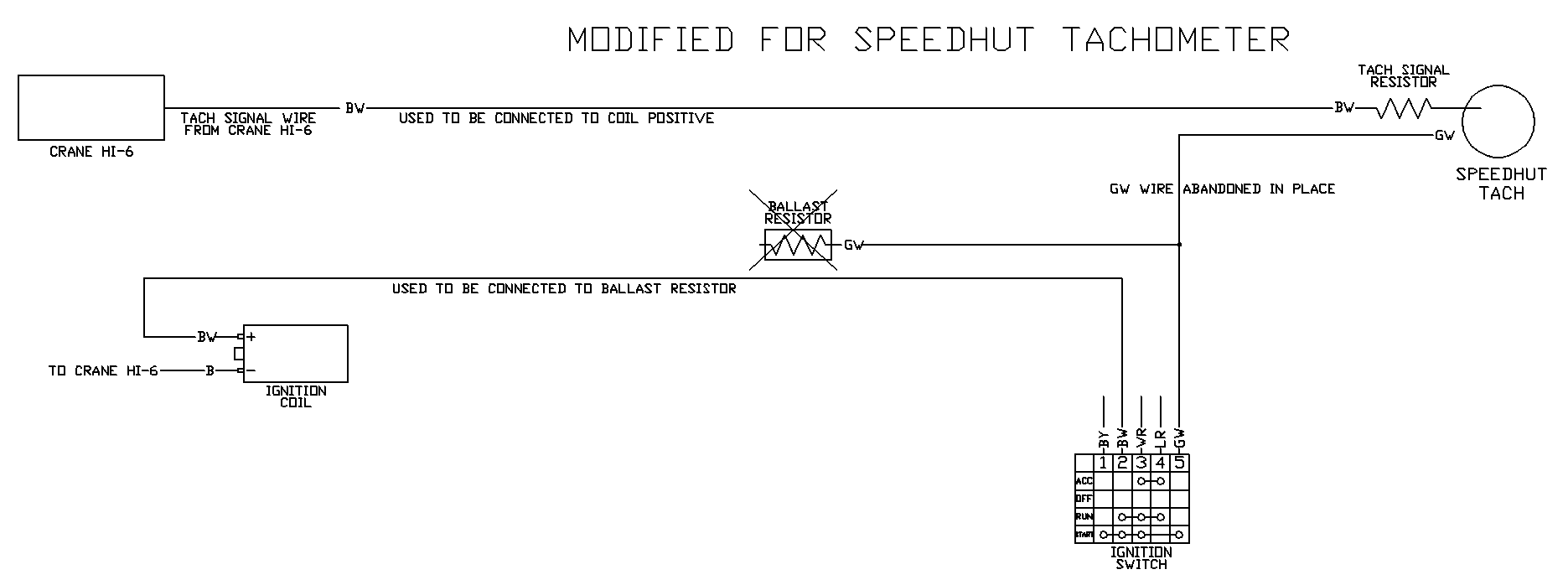
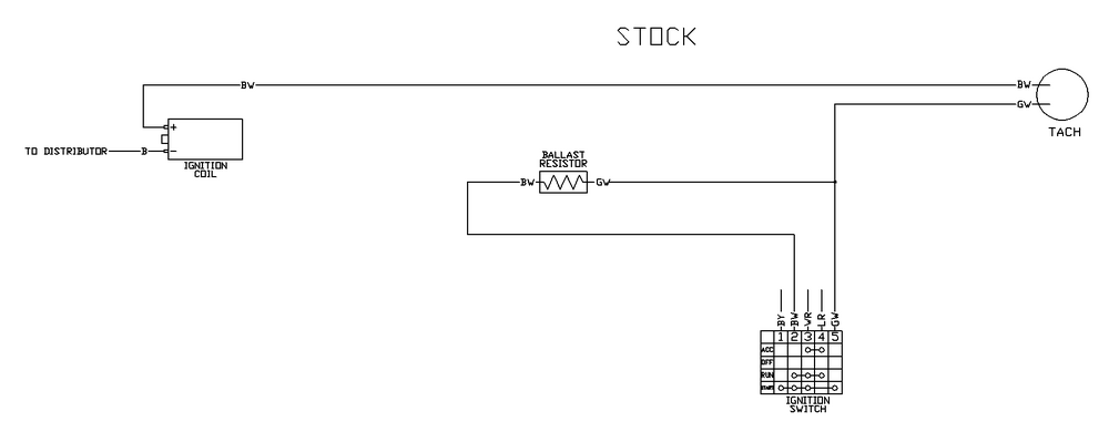
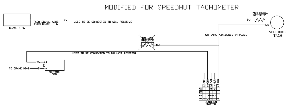
To combine what we talked about on the phone with the guidance from @cgsheen1, here is the stock wiring. This is essentially what the modified wiring would be.
-
While the wiring diagram shows a fusible link at the alternator, I personally have never seen it in the wild. The output from the alternator goes to the battery through the ammeter. If you do not have continuity from the alternator output to the battery, that usually indicates the ammeter failed or the fusible link at the starter failed. In either case, the car would not start/run (unless it was hacked up by a previous owner).
-
Yes, it can be checked, but there is a risk of shorting out the fusible link if the owner does not insulate the end of the alternator wire properly. I try to lay out the tests to minimize the chance of introducing another problem.
-
Well, the diode seems to check out. Test for voltage at the white/black wire with the key in ON when you get the alternator put back in.
-
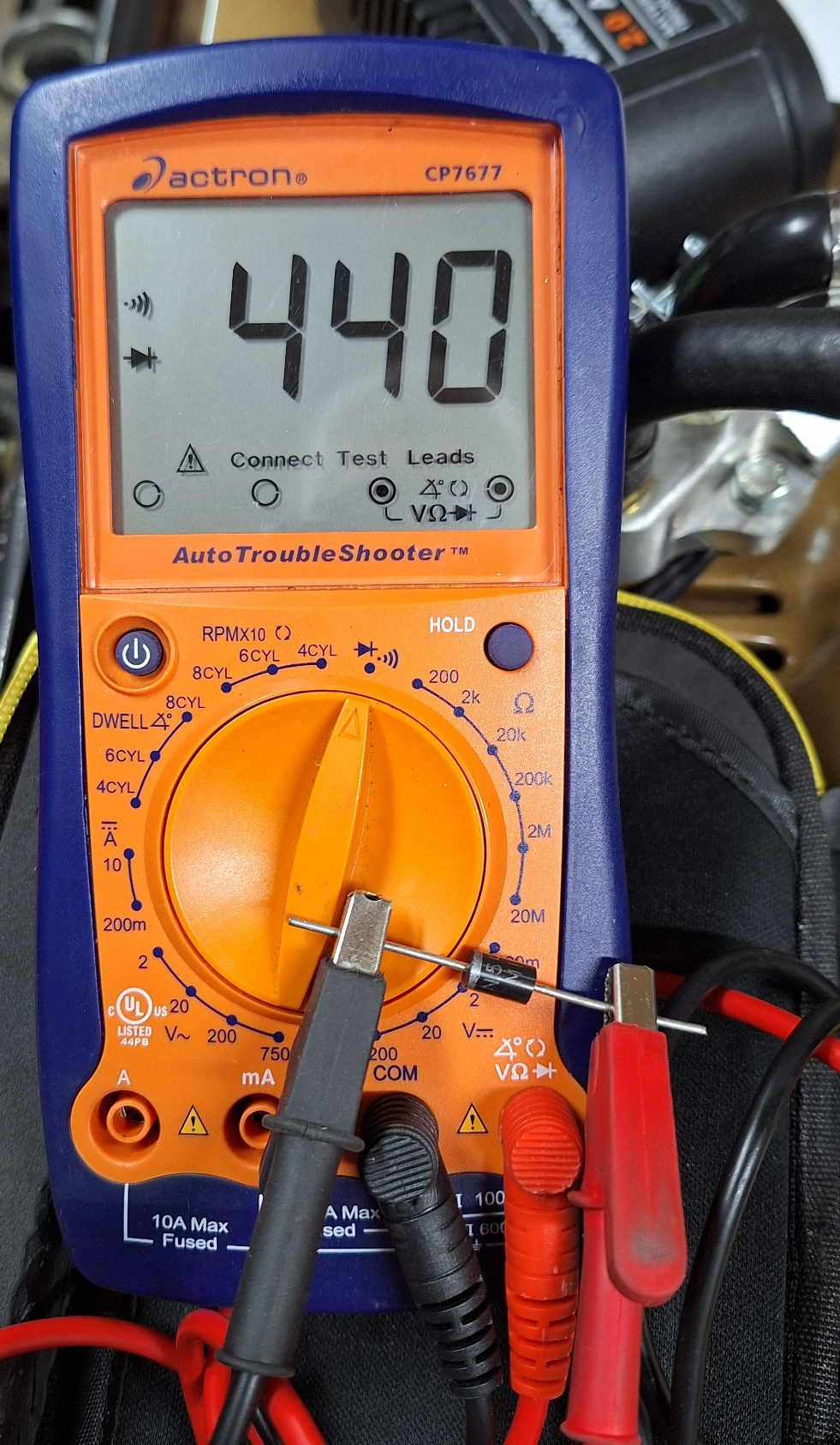
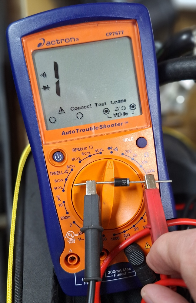
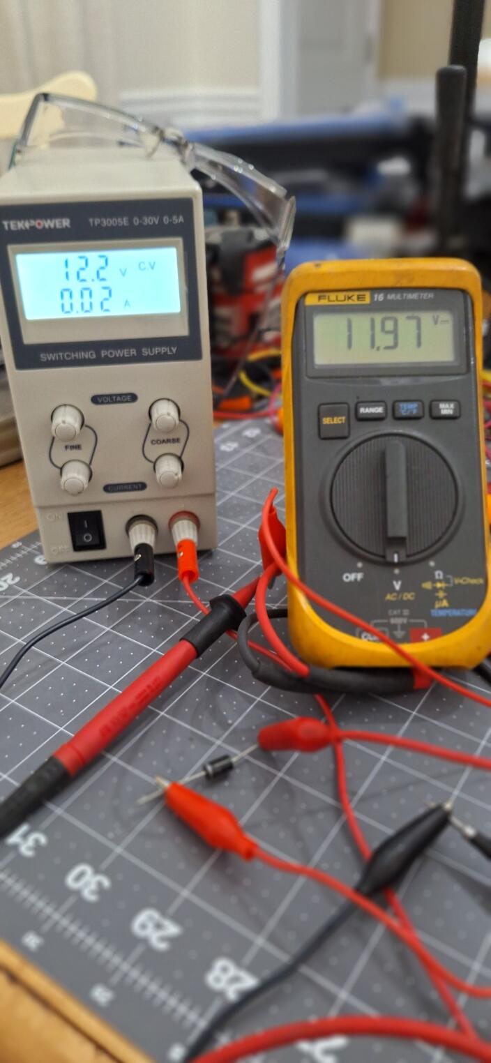
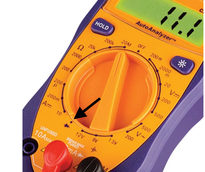
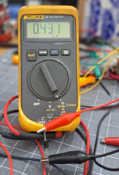
Of course, there is one other possibility. I could have designed the test wrong. I dug out a diode that should be the same spec as the ones used in the plug and tested myself. I found my instructions were lacking. You should re-test with the meter in diode testing mode. You can leave the key in OFF, too. If you test from the ballast resistor to the white/black wire, you should get a result similar to this: With the leads swapped, you should see this: If you do the voltage test, you should see a little less than battery voltage as the diode causes a slight voltage drop.


-
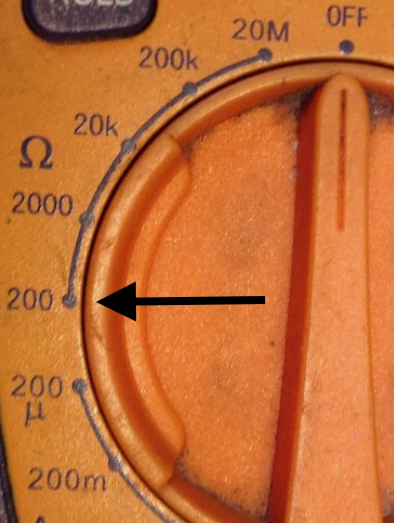
The 200 ohm setting is the correct one. The reading for the first test should have been close to zero. The reading you got was >200. That means either you didn't have good contact on the testing points, the diode is bad, or something else is wrong with the wiring. The way to confirm is to put the alternator back in, connect the battery, put the key in ON, and check for voltage to ground on the white/black wire. If you don't have voltage under those conditions, the alternator won't charge when running.
-
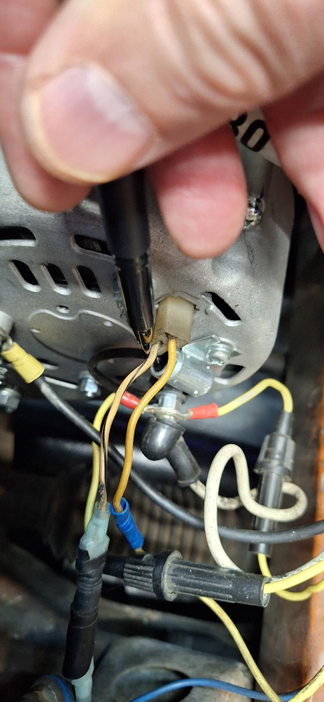
Okay, I'm going to assume the battery is disconnected. Put the key in ON. Put your meter on resistance. If there is more than one setting, put it on the lowest setting. Put the positive lead on the black/white wire at the ballast resistor. Put the negative lead on the white/black wire at the T connector. (Yes, you'll probably need some help. Record the reading and report back. Swap the leads and remeasure. Record the reading and report back.
-
Contact Oliver at Zspecialties to see if he has any. https://zspecialties.com/ I suggest calling him at the number at that website. Over at zcar.com, his user name is zmanofwashington.
-
Put the key in ON without the car running. Check for voltage to ground on the lower pin of the T connector on the back of the alternator (white/black wire). It should be about battery voltage. If you don't have voltage on that terminal, the alternator won't supply power.

-
Give me a call
-
Here's another site I've used before: https://www.nissanparts.cc/search?search_str=39628-E4100
-
There isn't a clickable link. NissanPartsDeal.com might be a better choice: https://www.nissanpartsdeal.com/parts/nissan-bolt-driveshaft~39628-e4100.html
-
Good question. Pull the parking light fuse and see if things change.
-
Have you tested or tried to rebuild the horns?
-
Green/White = Positive for gauge lights Red/Blue = Returns gauge lights to the rheostat (gauge light dimmer) Blue = Accessory (Key Switched) Constant power would be come from the cigarette lighter (Blue/White)
-
Go down to the "Push Rod Considerations" section of this link: https://www.evcreate.com/installing-the-ibooster/
-
Either he's making it harder than it should be, or this is not a conversion for the faint of heart.
-
Here's someone adapting the iBooster to a Z32.
-
If the clevis pin lines up with the pedal, you're good to go. If you're truly curious about this conversion, look on ebay for Honda electric brake boosters. You won't have to worry about the angle on the MC reservoir.