


.JPG.cfcada9cf1c1b502df3f5f2f2ca3ff36.JPG)

SteveJ
Community Member
-
Joined
-
Last visited
Everything posted by SteveJ
-
It's not often a guy can keep his wife and girlfriend around so long. 😉
-
I just installed a Nissan Frontier alternator in the 260Z. I bought a new alternator from Rockauto. I did a video on it here.
-
Could someone have pulled the wrong part for you? They clearly show their other yoke is 24 spline. Just as an aside, I did a search on Summit Racing for 26 spline yokes. There are plenty of hits, but I don't know if any of them would work. The only yoke I have lying about is from when I tore up the u-joints on my driveshaft 6 years ago.
-
You're routing the black and red wires from the 123 over to the coil. You might as well route the blue one there, too, and ground it on the coil mounting bolt.
-
The lowest resistance ground is probably at the distributor mount. See my video linked below. You have the large gauge cable firmly attached to the starter. The starter is firmly attached to the bell housing that is firmly attached to the engine. Unless you have a large gauge cable firmly bolted to the chassis, the engine will have less resistance. I just went down to my garage to verify. From battery negative to the distributor mounting bolt, the meter read 00.0. From battery negative to the shock tower or bolt for the coil, the meter read 00.1. The 00.0 tells me resistance is probably less than 0.05 ohm. (I'm not sure at what point it might round up.) Either grounding place (engine or chassis) should work as long as the surface at all the grounding points is clean and not corroded.
-
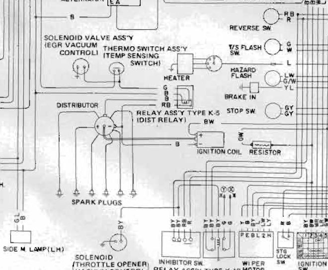
I misunderstood your question. The wiring diagram shows the black wire going to the negative of the coil. At the distributor, it meets up with the RB wire. (It could be RB from coil negative to the relay for all I know.) The coil positive should have the BW wire as I mentioned earlier. The RB wire goes to the relay that controls the advance for the dual point distributor and when the contact is closed, it goes to the black wire that goes to the other set of points. Pages EC-11 and EC-12 describe the system. When the car is cold, the temp sensing switch contacts are closed. The relay coil is energized, and the RB wire is connected to the black wire that goes to the advanced timing points. When the car warms up, the switch opens and the relay is de-energized. The contacts open at the relay, and the RB wire is open, leaving the retarded points in the ignition circuit. The 123 is not dual point to my knowledge, so you don't even have to worry about that wiring that I just explained. Without knowing which 123 model you're installing, I just grabbed one of the drawings. I can revise my explanation with more information. The BW wire goes to the coil as normal. No other stock wires go near the coil. (Jumper the GW and BW at the ballast as I mentioned before.) The black wire from the 123 goes to coil negative. The blue wire gets grounded. If the wire is short, you can ground it to the distributor mount.
-
A bad VR can drain the battery. That was one of my first Z car lessons over 28 years ago. For the inhibitor switch, look at the 73 wiring diagram for Automatic Transmission. Here's how the wiring works: The reverse switch AND the inhibitor switch are fed by a red wire. Each device is wired to a red/black wire that goes back to the reverse lights. I think this is a red herring (no pun intended). Anyway, the inhibitor switch should also have two black/yellow wires going to it. In other words, the inhibitor switch interrupts the solenoid power. No need to tie the 123 to anything but the black/white that goes to coil positive. There should be another wire from the 123 to coil negative to ground the negative when the distributor wants to fire. The stock wiring has a black wire that goes from coil negative to the points for the points to ground when it's time to fire. Then if there's yet another wire for ground, it could be grounded to the block for all you're concerned. Post the 123 wiring diagram to confirm. As for the green/white and other black/white at the ballast resistor, you can probably jumper those together.
-
Another Beverly Hills Car Club special...I'm not sure if someone else has posted it, but I just have the image of these twits searching through wrecking yards for cars to sell. https://www.hemmings.com/classifieds/dealer/datsun/240z/2454374.html

-
And another spammer just joined. https://www.classiczcars.com/profile/39043-ruhi-kapoor/
-
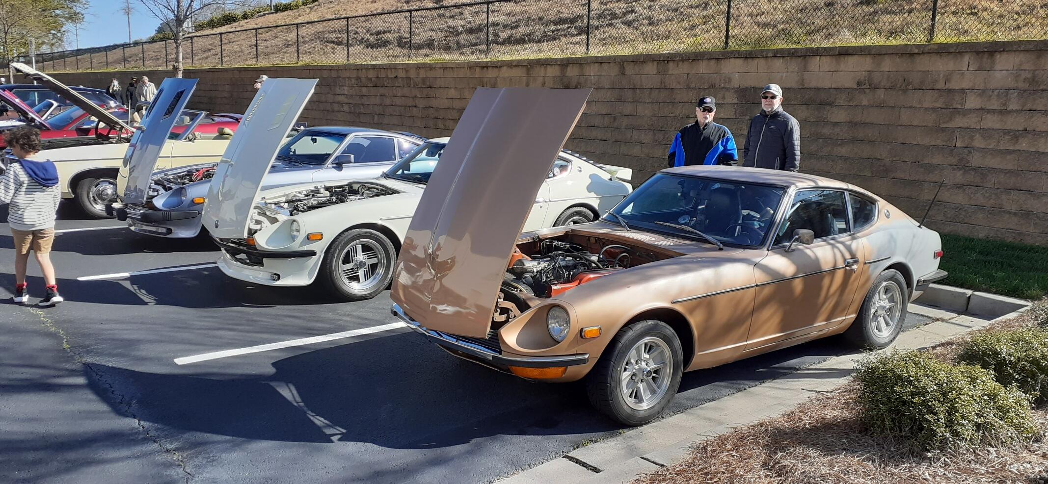
Just let us know if there is anything else we can do to help, @Mike. We're all a part of this community.I took the car to a meet today. Aside from a short test drive after replacing the brakes, this was the true test of my work (and diagnostics). Sure enough, the pulling to the left is gone. It's about time for me to pivot to the 260Z and get all of the parts together for the rear bushings to see if I can fix the toe-in on that car. Here's a photo from the meet with a couple of fellow GZC members.
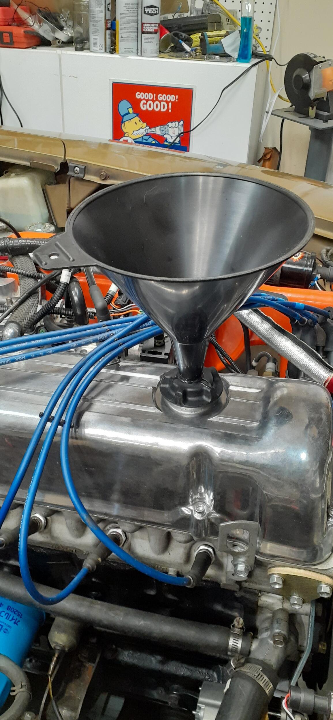
 I hope not. I would get kicked off this site...and you guys thought I was a real person.Strange. I'm not getting those warnings, yet.Yep, that's the inspiration. He only wants $15 US, but it costs an additional $20 to ship to the US. It was only about $8 in parts for me to make my contraption. If shipping was only half as much, I would have purchased his.So I ran across a post in a Facebook group from a guy in Australia who has made a 3-D print of an oil fill funnel that screws into the valve cover. I have a similar one for my non-Zs, and I found it to be a handy tool, preventing a lot of spill opportunities during oil changes. However, while the guy's price for the funnel is reasonable, shipping to the US more than doubles the price. Owing to my redneck heritage, the wheels starting spinning in my head. It was about time I broke the rust loose in there anyway. I figured that there had to be a way to improvise a similar solution. By golly there was. I bought a cheap aftermarket oil cap and drilled progressively larger holes until I got it up to 13/16 diameter. Then with an old funnel lying around the garage and some Harbor Freight 2-part epoxy, I think I have a solution. Behold...
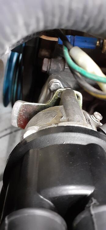
 Just another random Amazon buy...It was the first meter I had handy that wasn't autoranging. Otherwise I would have used the Fluke for the video.Those readings seem high, though it could be, in part, due to technique. Watch this video of me taking resistance readings on the grounding points and battery. If it was working well before you did the work, the first thing to do is to check over what you touched to see where you messed up. That's my starting point on a lot of troubleshooting.The coil is not grounded full time. It is only grounded when it is triggered by the ignition system. It sounds like you are saying that in your configuration the positive is coming from the ECU. I am not familiar with Duffy's car, I have no idea how he wired his ignition or tachometer. If firing when attempting to start is intermittent, verify the Hall effect sensor is working properly and the ignition system is grounding when getting the proper signal from the sensor. It sounds like you have done that already. What is the resistance from battery negative to the grounding screw in the photo? How about resistance from battery negative to the grounding post on the alternator? Again, if you have the stock connections on the battery, you have a large gauge wire to the starter and a smaller gauge wire (around 10AWG or so) going from the battery negative to the firewall. If you don't have the second wire, your grounding could be compromised. The starter is firmly bolted to the bell housing which, in turn, is firmly bolted to the block. The cable is the weakest link in that chain. The next weak link is corrosion on fasteners or between components. Also, don't be afraid to take a resistance reading between the engine block (unpainted surface like the bolts around the timing chain cover) and the shock tower studs. Have the meter on resistance, not continuity. You want the number, not a buzzing.Oh, I did find someone on ebay selling NOS 200SX clocks. I bought one to see if I could transfer the works into a 240Z clock. It was a fail. The mounting points were different, and I am not clever enough to fabricate any adaptations.Modify your own - https://hyllest.wordpress.com/2014/09/28/quartz-clock-movement-into-a-240z-clock/Again, please post a photo from your car. Maybe someone else understands what you are describing, but something is lost in the translation for me.Post a photo of where the oil is coming from. From Rockauto's website: It's been a year or so since I took one of these fuel pumps apart, but I see what almost looks like a weep hole in this view.
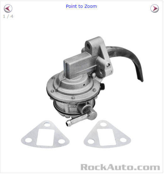 First answer...is a question. Are you not running the battery negative to the starter? Stock has the battery negative (4AWG to 2AWG) running to the starter with an auxiliary wire around 10AWG bolted to the firewall. You want a solid mechanical contact to both the starter and firewall with no paint to interfere with the contact. Second answer...is another couple of questions. What do you mean by terminated and secured? In wiring, terminated means installed at the appropriate location, and secured means you have bundled the wires so they can't get pulled loose. Why are you calling the green/white wire a ground? In the stock wiring configuration with the Key in ON, Battery positive goes to the starter connection point. From there, it goes to the fusible link and to a white wire. The white wire goes to the Ammeter and comes out white/red. The white/red goes to the ignition switch where it comes out on the black/white wire. The black/white wire goes to the ballast resistor and goes to the green/white wire. The green white wire goes back to the tachometer to drive the signal for the tach and comes out black/white. That black/white wire goes to coil positive. When I installed a Pertronix ignitor in my 73, I removed the ballast resistor and connected the black/white from the ignition to the green/white going to the tachometer. That way there was still a signal driving the tach. So your questions also drive more questions. Where are you getting the voltage for your coil? Do you still have the stock tachometer? Why are you looking for a ground wire near the coil? What circuits are losing grounds?My bill is up 2%, but it will go up more when I increase the value on the 240Z.


Important Information
By using this site, you agree to our Privacy Policy and Guidelines. We have placed cookies on your device to help make this website better. You can adjust your cookie settings, otherwise we'll assume you're okay to continue.