.JPG.cfcada9cf1c1b502df3f5f2f2ca3ff36.JPG)

SteveJ
Community Member
-
Joined
-
Last visited
Everything posted by SteveJ
-
I'm glad to hear your injuries weren't more severe. Let us know how things work out for you.
-
Give me until sometime on Sunday to write up some advanced diagnostics for you.
-
-
I also sent you a text.
-
I can try to break down the circuit for you. The green/blue wire comes into the headlight switch. When the switch is in the #2 position, you should have 12VDC on the red/yellow wire coming out of the switch. That wire goes to the fuse box where it connects to the left and right headlight fuses. The left headlight fuse comes out to a red/blue wire. The right headlight fuse comes out to a red wire. They go out to their respective headlights. The red/black wire is for the low beams and goes back to the headlight relay. The red/white wire is for the high beam, and it also goes back to the headlight relay. The positive for the coil voltage is green/blue. The negative for the coil voltage is black/red. The black/red wire goes to the turn signal switch where is open or connected to ground, depending upon the switch position. When the coil is de-energized, the red/black wire is grounded, finishing the circuit for the low beams. When the coil is energized, the contacts connect the red/white wire to ground. So, if the headlight switch is on with the turn signal switch on low beam, how could you see 12 VDC on both sides of the high beams? If you don't have the ground at the relay, you only have potential voltage. The headlight elements acts as a piece of wire and not a load. That's why you see voltage on both sides. The voltmeter has significantly higher resistance compared to headlight element.
-
I ended up buying some wedge sockets and LED bulbs in the appropriate colors for their sockets. I replaced the existing sockets with the wedge sockets, removing the lenses. I used uninsulated butt splices covered in heat shrink tubing to splice the new sockets in. The gauges can be removed without pulling the dash. Get a copy of the factory service manual (FSM) for instructions. It worked for me.
-
Thanks for the offer. Fortunately, I bought a spare 10 or 11 years ago when a Z dismantler in Albuquerque was closing up shop. I was just making sure you were offering a 73 hazard switch since it is unique to that year. I'd hate for you to send a switch to him only to find out that it won't work. Save it for the next person who needs one.
-
Do you have a spare 73 hazard switch? That was a one-year only switch.
-
Show photos of the current condition of the hazard switch.
-
Now this I might be able to work with. I have a 70/71 fusebox hiding in my garage somewhere. I'll have to take a look at it and give you my opinion.
-
Please elaborate. What wires do not match up? Are you talking about colors? Are you talking about connectors?
-
Just promise to post lots of photos when you get your hands on it.
-
It's not a stock socket. Stock sockets in the 240Z are grounded to the gauges, IIRC. The green wire on that socket should be your ground.
-
Both my 73 & 74 have three screws securing the ring to the filler neck. I'll try to remember to post photos for you.
-
Both my 73 & 74 have three screws securing the ring to the filler neck. I'll try to remember to post photos for you.
-
Make that a late 260Z. My 260Z has a filler neck identical to my 240Z.


-
Make that a late 260Z. My 260Z has a filler neck identical to my 240Z.
-
Make that a late 260Z. My 260Z has a filler neck identical to my 240Z.
-
Make that a late 260Z. My 260Z has a filler neck identical to my 240Z.
-
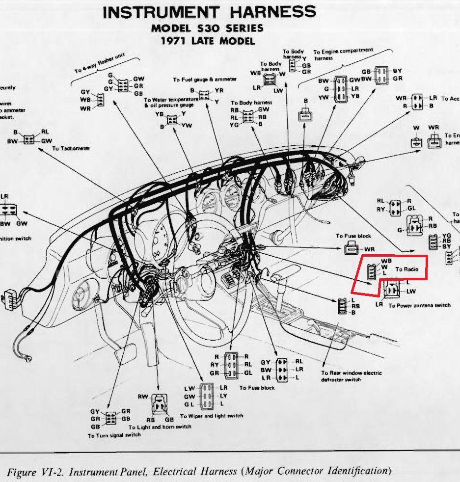
It's definitely for the radio. The challenge is to find a wiring diagram that shows the white and white/black wires.

-
This is similar to what I had in my mind's eye. I was thinking that the block could go into the notch on the ring.
-
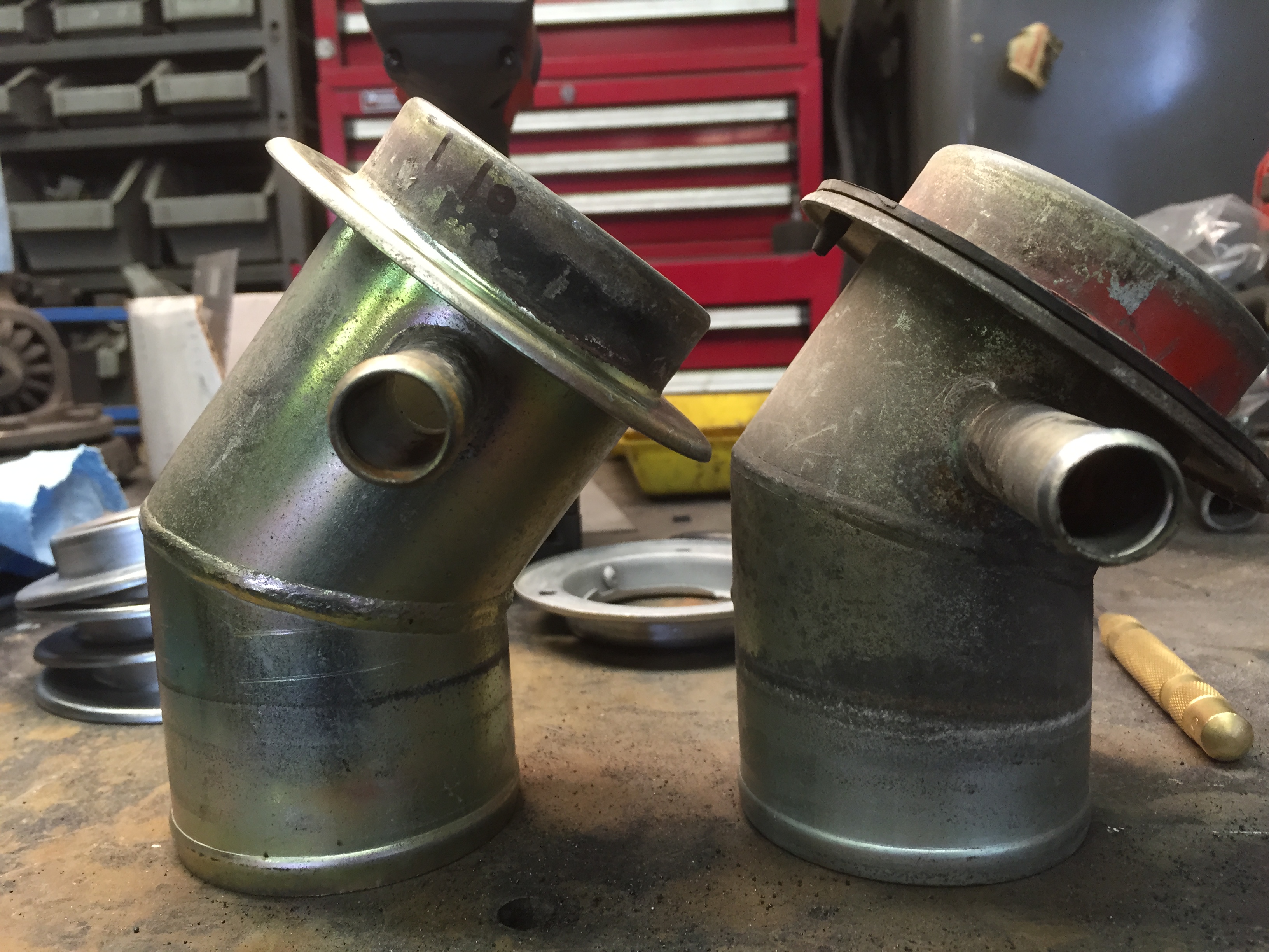
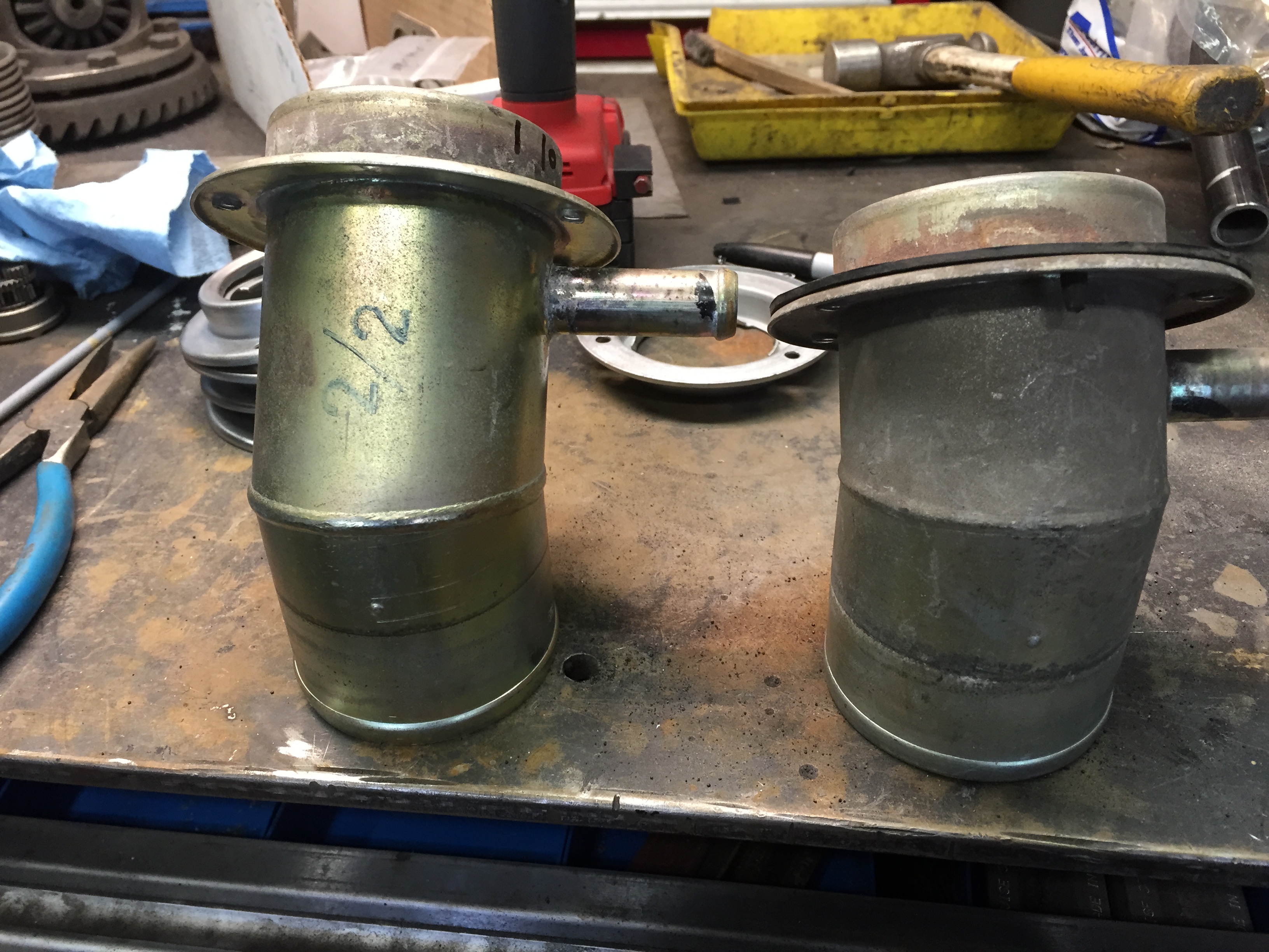
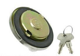
Scene: Chevy Chase is on the phone as Don Pardo announces, "And now Weekend Update with Chevy Chase." Chevy: "No...that's just what they call it...No, you don't actually blow on it." Looks up. "Uh, I've gotta go." Hangs up phone. "Our top story tonight..." To Mark's post, here are pictures of the BMW cap and Z cap. About the only way for the BMW cap to latch would be to clamp down on the ring. You can see the possible range of motion on the BMW cap. Ideally for a locking cap would be for a block on the cap to slide to slot on the ring to keep the cap from turning.
-
At least you guys could get the cap onto the car. I bought a BMW 1600 gas cap, and it didn't fit. The good thing is that it's easy to remove the ring and look at the fitment for locking purposes.
-
I bought a couple of sets from Black Dragon a couple of years ago, but installing them hasn't made it to my 'round-to-it list.
-
What does it look like underneath? How about in in the engine bay, especially around the battery tray and brake master? Is the car usually parked outside with the nose going downhill? If so, watch for rust around the hatch sill.