


Captain Obvious
Community Member
-
Joined
-
Last visited
Everything posted by Captain Obvious
-
I just published my book report in that other TPS thread.
-
I took a quick look through some of the docs and there appears to be three methods for setting the switch. First method is the "measure the angle of the throttle valve at which the switch opens" method. Page EF-56 (of the 75 FSM) says the switch should open when the throttle valve reaches about 7 degrees. (Note that page EF-57 of the 77 FSM says 4 degrees). Second method is the "measure the gap between the throttle linkage and the throttle stop" on the throttle body method. This method is described on page EF-62 (75 FSM) and EF-63 (77 FSM). They say this is how you adjust the switch if you have the throttle body loose on a bench and are replacing the switch. I don't know why they didn't employ this method all the time? Maybe because it's difficult to do with the throttle body on the car? Third method is the "raise the RPM to a certain level and set it so that's where the switch opens" method. This method does not seem to appear in any of the FSM's, nor does it appear in the 76 version of the FI manual (the "FI Bible"), but it DOES appear in the later (1980) version of the FI manual. Pages 126-127 of the 1980 FI Bible say to raise the idle to 1400 RPM and set the switch there. Most notable is that the 1980 FI manual ALSO mentions the "measure the gap" method, but says you should only do that when you can't use the 1400 RPM method. They say the 1400 RPM method is the "preferred" method. Looks to me like the 1400 RPM method superseded the previous methods? I guess I would use that if I had to? That's the results from my book report. Then I went downtown. To look for a job.
-
Hmmm... Nothing like a well thought out follow-up question to get you to fill leaky holes in a previous opinion. Haha! If I were selling a 240Z, I guess it would come down to the condition of the rest of the car and if I considered it "collectible" or not. If I thought the car had solid standing as "original", then I could value the original factory equipped transmission higher (regardless if it were a 4 or a 5-speed). By that, I mean if someone could unquestionably prove that transmission was bolted to that motor left the factory in that car on day one, then I would probably consider that trans as having collector "originality" value. But only if the rest of the car supported that situation. If the exterior had already been irreversibly changed (fender chopped out and flares added, spook instead of original front, etc) and the engine had been changed (someone swapped in an L28 but kept the original trans) and the interior had been irreversibly changed (roll bar), then having the original transmission would mean little to me. In that situation, I would NOT mention the trans being original in a for-sale ad. Unfortunately, I'm not in a position to purchase a collectible 240Z. Now that the prices are rising so quickly, I guess I missed my opportunity. And since I won't be buying one, I guess I won't be selling one. "Driver quality" only for me, and the transmission thing is low on the list.
-
No, thankfully I have never done a roof replacement to get rid of a sunroof. I've seen a couple people here on the forum get involved in that, and their (unpleasant) experience is what has driven me to put that so high up on my list. I'm with you... I'd much rather do a trans swap than deal with that!! Hmmm... Maybe I should move sunroof up even higher.
-
So I changed up my order just a little bit. I moved the chopped-up rice rocket to the top of the list. Why? Because at that point, it doesn't matter to me if it's clean or rusty, I'm not interested. If it's been chopped, tubbed, flared, whatever, beyond being able to be put back stock-ish, then I don't care how clean it is. I just can't. Oh, and I put in a line for sunroof and auto trans. Four-speed vs. five-speed is still #374
-
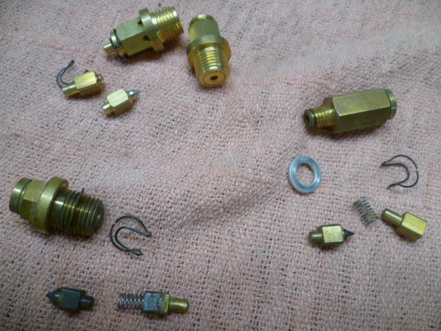
Gotcha. Here's a pic of some float valves where you can see the guts. There are a bunch of different styles floating around out there made by different manufacturers, but most of them are the same concept. It's been many moons since I took that pic, but I think the ones at the top are aftermarket flat-top, the one on the bottom left is OEM flat-top, and the one on the bottom right is OEM round-top: Not claiming that it's an all inclusive list, but I've seen sticky valves from: 1) rubber tip turned to gooey gum from incompatibilities with today's fuel 2) corrosion on the brass bits (note some of that starting on the one in the lower left of the pic) 3) broken spring 4) Crud built up inside the valve interfering with the movement of the guts 5) insufficient fuel line pressure to overcome the cracking pressure of the valve In any event, happy hunting and I'm glad you found the smoking gun!
-
Yeah, that's not a new issue. The two choices are trim the bushings down, or jam it the heck together by compressing the urethane. Putty knife comes to mind... I don't consider either of those a fantastic solution, but given those two, I would trim just enough off the bushings so that jamming them together doesn't make you wince.
-
Cool! Glad you found the root cause. So this sort of thing SHOULD have shown up on a bowl level check, but I'm guessing you never had the bowl sight glasses attached at the exact time the problem occurred? Also, do you know WHY the float valve was sticky? Is it something inside the valve itself, or is it friction between the float tang and the valve stem? That could be valuable info.
-
I'm certainly no expert on the collector value thing, so keep that in mind, but here's my thought on the matter. Here's my quick list of what I would look for when buying any Z, including a 240Z: 1) Has it been molested into a rice rocket JC Whitney abomination with fender flares, lowered, RB motor, fender mirrors, roll cage, fuel cell, go-faster stickers all over it 2) Rust 3) Rust 4) Rust 5) Does it have a sunroof, or is it an automatic 6) Rust 7) Rust 8) Is it a half finished torn apart molested project mishmash of different cars and years 9) Rust 10) Does it run and drive. At all 11) Rust 12) Does it have an interior. At all . . . 374) Does it have a 4-speed or a 5-speed. Like I said, I'm no expert, but that's my list.
-
I've found problems with the on-line compression ratio calculators, so I'm not confident in the numbers you mentioned. I've done a little work on my own calculator and I come up with 8.3 for an N42 with dished pistons and 10.25 when used with flat tops. If you're really wanting accurate numbers, let me know and we can get into it here in the thread.
-
Jeff, Please don't tell us any more details about what went in the dumpster. I (and probably lots of others here) really just don't want to even think about it.
-
How many joints in a lid?
-
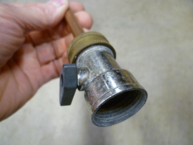
That stove top stuffing is probably remnants of someone using one of those products that is supposed to stop leaks. I didn't have a pressure washer, so I made a little garden hose blaster instead. Of course, a real pressure washer would have been more powerful and presumably more effective, but it's what I had access to at the time. With "standard" household garden hose pressure, my contraption will shoot about thirty feet, so it's not bad. Cobbled together from stuff I had laying around. Looks like this: Here's the business end. I just crimped down the sides in a bench vice. Very scientific like: Soldered a piece on the end to adapt to a hose: And put on an in-line hose valve: It's small enough that (with the freeze plugs removed) I could reach up inside the block and around the piston jackets into the dark recesses.


-
That starting time on the Z is perfect. One final thought on the matter. I once used an ebay purchased cheap-O in-line check valve and it didn't last. Worked great for a month or so, but then the internal seal started to curl and wouldn't seal anymore. Presumably from incompatibility with ethanol in the fuel? In any event, the point is... If you used a el-cheapo valve, it should get you through this current transport move situation, but don't assume it'll last for years. And good luck with all of the new venture!!
-
Just to be pedantic... None of them use Amphenol connectors. It's Amp, not Amphenol. I can't believe those two companies even existed at the same time. Both selling connectors.
-
That's what mine does. And looking at the valve, I think that's what is to be expected. Good luck with the weekend tests and let us know what you find.
-
I'm no expert on the topic, but from what I've heard the numbers you listed as your goal would be excellent. Maybe cruise just a little bit leaner? I guess that depends on how likely the engine is to incur pre-ignition, right? If it's an engine that's designed "not to ping", then you can run leaner? Anyway, there are guys here on the forum much better versed in that stuff than I am. As for the plan about testing with the EVAP completely plugged off and then again with it connected... I think that's an excellent idea. That'll give you an idea of what's going on. In theory, the only change you should see is that your cruise number should get a little leaner with the carbon can connected.
-
Well I'm not sure I have an explanation for which hoses hold vacuum and which ones don't, but it sounds like your EVAP should be in better shape now than it was before. So, looking at that carbon canister cap valve thing... Notice how the spring pushes the valve into the open (purge) position. Also notice how the control vacuum line (smaller upper) pulls the valve into the open (purge) position. The question I can't easily answer is "The control line pulls the valve from above to open it. But the valve is already being pushed open by the spring from below. So what is it that ever CLOSES that valve?" And that's where the theory of the high manifold vacuum helping to pull that valve closed comes into play. So when do we get the next round of A/F readings now that you've fixed the cold start injector and (hopefully) the EVAP stuff?
-
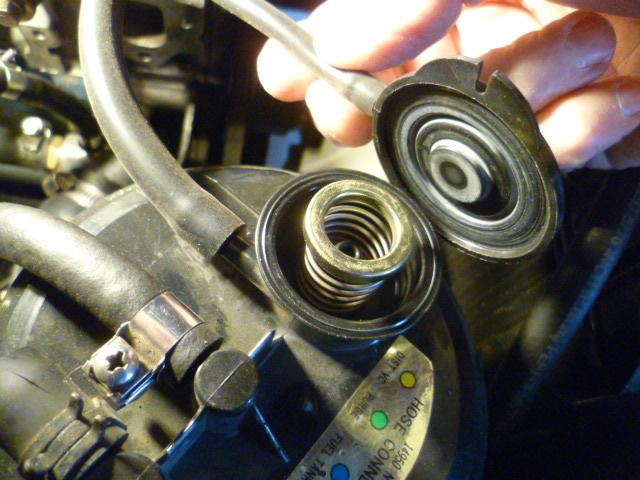
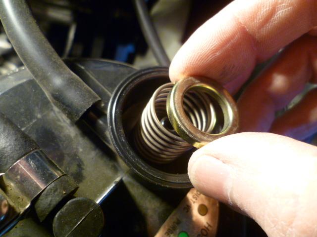
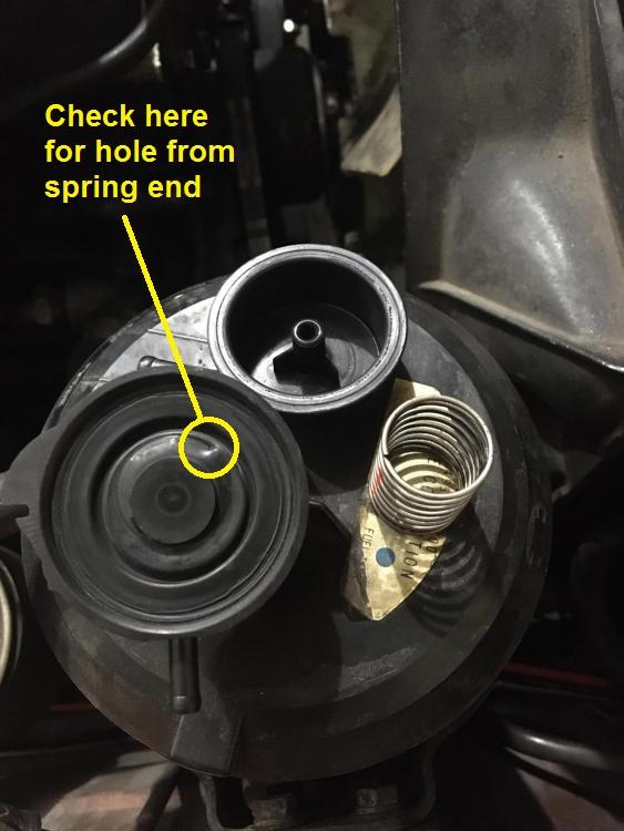
What a coincidence... I didn't have any pics of my evap system to refer to aid the discussion, so I popped the cap off mine and took some pics too. Haha!! So, I bet I know what's going on with yours... I had mentioned earlier that there's not much to it. A diaphragm, a spring, and a metal ring seat for the spring. Well, you're missing the metal ring seat for the spring. I believe it's purpose is to keep the end of the spring a metal surface to press against to even out the pressure and keep the sharp pointy metal end of the spring from poking through the soft rubber diaphragm. Well you don't have the seat, and my guess would be that your spring has poked a small hole through the diaphragm. Inspect carefully at the dent where you can see where the spring was pushing: In any event, it's supposed to look like this: And I also verified that my small control line does hold vacuum. About attaching the large line directly onto the post down inside the cap where the spring lives? I think your assessment is correct. It'll be continuously purging at all times. Probably just fine at everything but idle. At idle, you might find it runs it lean again. I don't know if you have enough compliance travel in the mixture screw to compensate, but if you're just looking for an option to try until you can find a new can (or at least diaphragm and spring seat) it's worth a try. If you find you can compensate with the idle mixture screw, you should be fine.
-
Haha!!! That'll do it! Wiring looks great. It's going to be a whole lot better with those new connectors!
-
So in the pic, there are rubber bellows and bump stops, but in the completed pic, neither of those were used. Why not? Didn't fit well? Just didn't like the look?
-
The small canister hose should hold vacuum at all times. If it doesn't you might want to pop the cap off the carbon canister and have a look around. The big canister hose will not hold vacuum with the engine off. And that's my little bit of confusion about the system. The FSM talks about the large line as being sealed until the control lines opens it, but in my experience, that is not the case. My theory (that I talked about a little earlier) is that the high vacuum source pulled directly from the intake manifold actually helps pull that large line into a closed position. As for the other question about not changing the idle... It's probably because that small line (and the distributor advance) is pulled from a ported vacuum source. And at idle, there's no vacuum so nothing gets pulled into the intake tract. In other words, it's not a vacuum leak on that throttle body nipple unless the throttle blade is in a specific position. At idle, there's no vacuum, and at WOT there's no vacuum. The only time there is vacuum there is at a light cruise position.
-
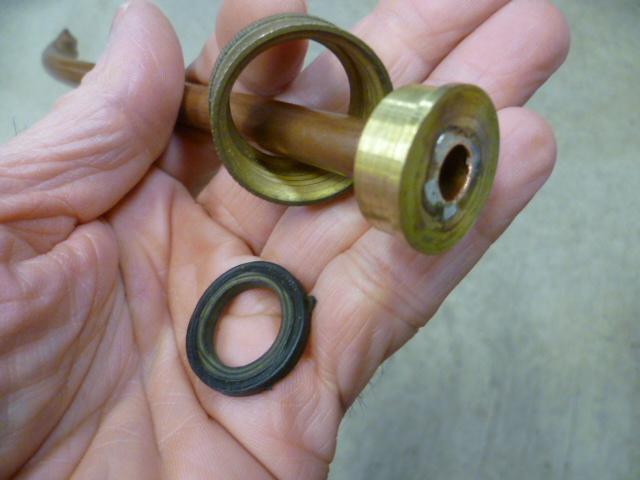
Your old seal did have metal in there. If you didn't see the metal, it's because It had a rubber coating over the metal. But there was metal inside. They usually make those seals in a couple different varieties like that. The general concept is that the ones with the rubber coating on the outside are better sealing when used in an application where there sealing surface has some imperfections or the hole that it is being pressed into has a split in it (like the rear main seal). Might beg the question then of "so then why don't all of them come with rubber on the outside?" and my answer is "I don't know. Maybe cost." Here's a page from McMaster that talks some about the differences: https://www.mcmaster.com/oil-seals/
-
Dome light looks good. Hope you like the LED when it comes in. So I have no experience with Keihlin, but I'm assuming the basic concept is the same for all of them. Just pay attention to the details and make sure everything is clean, clean, clean. And I can do without the carbon fiber goodness. Haha!!
-
Forgot about the valve on the CARB can... There's not much to it. A diaphragm, a spring, and a metal ring seat for the spring. I looked through my pics for something that might show the guts, but I got nothing. If the diaphragm doesn't have any holes in it and is installed correctly (not folded over), then I don't know what else to do there. Does the control line (smaller line shared with the distributor advance) hold vacuum? I do remember someone doing some testing on the valve... @Dave WM maybe?


