
Captain Obvious
Community Member
-
Joined
-
Last visited
Everything posted by Captain Obvious
-
Assuming all of the links over the course of the Z were made by Yazaki (and I suspect that is the case), the you shouldn't have to measure the conducting part of the link. The insulation thickness difference between those two series was different enough that you should be able to tell the diff between the two just by measuring the insulation diameter. The overall outside diameter of the (red) FTX-0.7 is 2.2mm. While the overall outside diameter of the (also red) FLWX-0.85 is 3.2mm. Should be pretty easy to tell the difference. And as to the discussion about the quantities of #5's and #6's... It appears that it's just another mistake in the documentation. On the pic, they are clearly indicating that there exists three number fives and one number six. But in the details below, they have those quantities switched. It's just another mistake in the docs. I wish my stickers were readable. It would add one more level of confirmation to the discussion if someone with a 77 or 78 could post a pic of their readable stickers.
-
Thanks Wayne!!! Looks great! This is a fantastic tool for all of us. Don't know what we would do without you.
-
-
I got the same impression about the melting spot as you did, but here's the rub... They clearly do the tin dip before they put the insulation on. And Yazaki don't know how long the end user is going to cut the length of wire. So if they are tin dipping just in select spots, they won't know where that dipped spot will end up (or how many will end up) in the finished product. I think the dip has to apply to the entire length. And as for measuring the resistance difference between the red and the brown, I don't have a meter anywhere near that good. Probably easiest to push an accurately known "highish" current through it and measure the voltage. But I gotta ask.... Why would you need to resort to measuring the resistance when you can just look at the jacket color or measure the diameter of the conductor with calipers? Based on the thicker insulation of the old style red links, I suspect they are the FLWX 0.85.
-
-
So for some additional info, I couldn't stand it anymore so I started playing around with some of the on-line translators. Everyone likes info, right? Here's a probably correct interpretation of most of the pertinent info on those Yazaki fusible link data sheets: The only thing I can't figure out is exactly what is the difference between the FLWX and the FTX series. It clearly has something to do with tin-dipping. My guess is that the FTX series uses smaller individual strands and then they tin dip the strands a second time once they are wound together. Might make them more accurate or have a sharper melt characteristic? Anyway, here's some datasheets. FTX (this is where the 0.3 brown comes from): And the FLWX (this is where the 1.25 black link comes from):
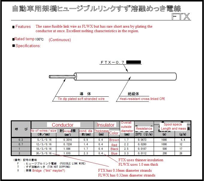
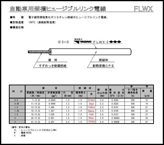
-
Well I'm pretty sure there isn't any 28 Ga wiring anywhere in the infrastructure. There might be some stuff that small as it enters components (like solenoids and the like), but I don't think actual wire in any harness is that small. In any event what you said about the 0.3... "if 0.3 hasn't been melting, what reason would you have to go to 0.5?" echoes exactly my note above when I said "anecdotally that the brand new 0.3 "sorta brown, sorta tan, sorta salmon" links I have installed run nice and cool. Implication being that they are large enough." So I agree... Why argue with success, right? Put the smallest, easiest to blow protective device in there that still allows the system to operate properly. The only thing I DON'T know is if I have ever operated my system under peak load. By that, I mean... I've never run the HVAC fan on full blast at night with the high beams on, while running the rear defrost, wipers, and hitting the brakes on a hot summer night while running the A/C and having the flashers on. Probably never will.
-
-
Fuses and other protective devices are not a field of expertise I've been even grazed by in my travels as an EE. But I can tell you that even though the whole thing sounds so simple and mundane, I highly suspect the experts in the field would be quick to refute that. In other words... I bet the people who really know what they're talking about in this facet of engineering (which isn't me) would be able to debate the finer points of this for hours. That said... I took a quick look on the web and came to the following conclusions: 1.25 mm sq is approx. the same as 16 ga 0.3 mm sq is approx the same as 22 ga 32 ga And also with some web searching, it seems that the "general convention" seems to be that the fusible link gauge should be four sizes smaller than the wires they are intended to protect. So, for example, 12 ga. wire should be protected by a 16 ga. fusible link. And 18 ga. wire should be protected by a 22 ga. fusible link. All that really makes me wonder if that brown 0.3 mm sq link is really really correct. Maybe that red link really was the correct one all along?
-
-
Is that a seam in the middle? Like someone took something designed for a wider car, cut some material out of the center, and then bolted the two remaining pieces together in a narrower configuration?
-
-
-
I had the camera handy, so I took some additional pics. Here's the correct position for the links on the 77-78. This time I took the pic from the angle that everyone likes. As it's shown in the FSM: And here's a pic that (although it's hard to tell), you can actually see that one of the White/Red wires is larger than the other three. That's the position that gets the largest (black) fusible link. The W/R wire gauge is larger to account for the higher current that circuit can potentially carry. Who knows... Since the blocks are just screwed to the fender well, maybe some of them have been switched around? So if you're looking for a way to definitively determine which location gets the largest fusible link, you can check the wire gauge sizes: And here's a pic of what remains of my fusible link labeling. Can't make out any of the color listings. Would be great if a 77 or 78 owner could post a pic of better condition labels, but this is all I got left. I can make out ??L (which I assume would be H-L) and "IGN", but that's it:

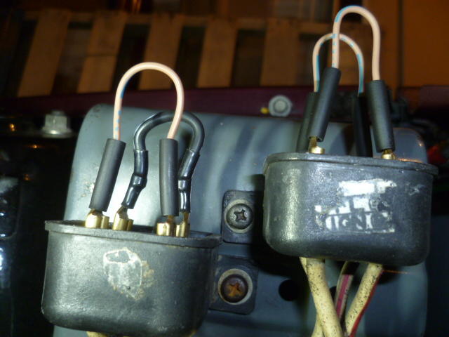
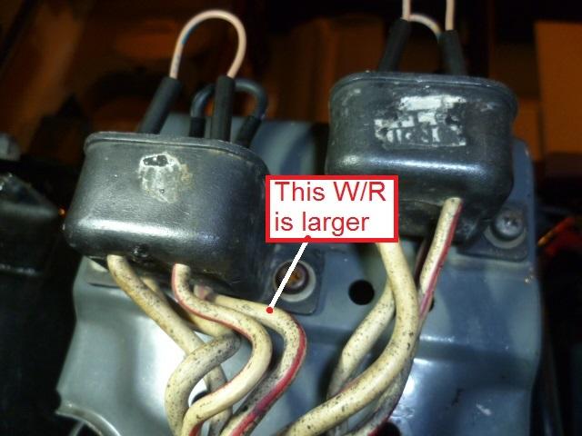
-
-
That's the way it's supposed to be. The inboard and outboard bearings both have the same ID. (FYI, same OD too): https://www.vsm.skf.com/us/en/products/GRW116 https://www.vsm.skf.com/us/en/products/GRW117 Part Number: GRW116Type: Wheel Bearing Part Information: Outer Diameter: 2.7500 in Inner Diameter: 1.2500 in Width: 0.687 in Part Number: GRW117Type: Wheel Bearing Part Information: Outer Diameter: 2.7500 in Inner Diameter: 1.2500 in Width: 0.8646 in
-
I replaced all my fusible links a little while ago (still need to post up a public service warning thread about that whole thing, but...) and I believe I saved my old ones. I'll take a look at my old red ones (that are truly red) and see if there's any writing on them. I keep then in the center console as emergency backups, but I may donate one to the cause and open it up. I should be able to measure the wire inside. I can tell you anecdotally that the brand new 0.3 "sorta brown, sorta tan, sorta salmon" links I have installed run nice and cool. Implication being that they are large enough.
-
OK. At least we talked about it a little. I remember that at the time, the priority was addressing the headlights so you didn't get caught in the dark. We may have glossed over the fusible links with "here's something else to take care of when you get a few spare minutes" or something like that. I'm just glad we could get a handle on the intermittent headlight issue and get you home with a definitive answer to what was causing the problem. Yeah, I know @wal280z is all dreamy about the fuse replacements (note that I didn't say "upgrade" ) for the stock system. He's that kind of guy. Lives for the bling.
-
-
-
Yes, I do believe the mis-placement did carry over from 77 into the 78 year. I think the location of the biggest (black) link never changed. I think they got it right on the diagram in 76 (right front), and then screwed it up in 77 which carried into 78. It would sure be nice if any other 77 or 78 owners could verify the position of the links just for additional data points. I know I've checked my 77 and positively determined the positions of the links. And I know that @240260280 did the same on his 77 some number of years ago. But I don't have any hard 78 data points. So for any of you 78 (or additional 77) owners out there who would like to participate? The easiest way to verify the link positions... Turn your headlights on. Remove the link that is closest to the fender and closest to the firewall (right rear) fusible link and the headlights should go out.
-
@gwri8, excellent! Glad we could solve a long standing issue. But I gotta ask... Did I pull the fusible link caps off your car in Atlanta and have a poke around? I know I messed around with the fuse block in the footwell and the multi-function switch on the steering column, but did I get up into the engine compartment? If so, I hope I would have noticed the links in the wrong positions. At least I hope I would have. I know it was a little drizzly at the time and we were rushed for time, but still.
-
Wow. That's some pitting. Are you sure none of those pits go all the way through? Was there oil in the pan in recent past, or did you purchase it dry? Yeah, that was my reaction as well. @ksechler did specifically say the braided lines didn't clamp well. Maybe the non-braided original lines aren't a problem? Hopefully he'll chime back in with more info?
-
-
Zed Head, The pic you posted from MSA is one of the biggest contributors to the problems with the fusible link locations for 77. This diagram is wrong for the 77-78: I don't know where it started, but it probably started from the FSM wiring diagram for 1977. Nissan (seemingly) tried to lay the components out on the wiring diagrams kinds-sorta in the same positions they are located on the car. Problem is they screwed up the position of the black link. On the factory wiring diagram in the manual, it has the black link on the fender side back position near the firewall. But on the 77 car (I myself personally verified with a meter) that the black link should be on the fender side FRONT near the headlight. So Nissan never really said "This diagram correctly locates the link positions on the car", but it sure can be assumed that's the case. Problem is.... It's wrong. And others (like MSA) have been propagating that incorrect assumption ever since.