Namerow
Community Member
-
Joined
-
Last visited
Everything posted by Namerow
-
Nice write-up, zKars. A few additional questions for you: For an SU application, what is it that creates the end-of-travel (WOT) stop for the system? Does the 'commercially-available arm' hit a stop? Does the pedal hit its stop? Or do the throttle plates hit their stops? How does this affect the travel distance of the pedal, from rest position (idle) to the point where the system hits its stop? Where did you source the M8 ball-sockets and the 'commercially-available arm'?
-
-
Non-chemists messing with chemistry = alchemy As an engineer, I hate 'hit-and-miss' when I know that science offers a better solution. Unfortunately, I'm not a chemical engineer
-
Hah! That depends on your definition of 'finished'. I completed everything I wanted to do, with the exception of the my hood prop rod. I bought a replacement prop rod from Zkars and it arrived after I'd put the chemicals away and after I'd given Grannyknot back his controllable power supply (which I suspect he figured he'd never see again -- Chris a remarkably generous, patient, and polite guy). Some observations from my electroplating experience: To anyone just getting started on a plating project, I recommend you ignore all the 'budget' plating articles you'll find on the internet. I spent so much time and money experimenting with these DIY, low-buck recommendations (epsom salts, corn syrup, vinegar, etc.) that I would have been better off spending $500 to get a commercial outfit to do the work for me. If you really want to do it yourself, just hold your nose and buy the (premium-priced) Caswell chemicals. They work pretty well, for the most part. Even with the Caswell chemicals, there's a lot of trial and error involved. To get a good end result, everything needs to be right and there's zero tolerance for parts that haven't been properly cleaned and prepped. I hindsight, I don't think electroplating scales down well to the 'hobbyist' level. Or to put it another way, I suspect that, 'The bigger the vat and the heftier the power supply, the better the result'. I had mixed results trying to do multiple small pieces at the same time. This just seems to increase the chances for error. The 'Mount Everest' for my S30 plating project was getting a good result for the two-piece engine inspection light housing. With it hollow configuration and welded-on mounting bracket, it's hard to get complete, even plating coverage over the outer surfaces. It took me two tries to get a result that I was (sort of) happy with. Plating longer pieces (like the hood prop rod or the rear engine coolant transfer tube) will force you to buy a double-quantity of the Ca$well chemicals in order to get a bath volume big enough to plate these pieces in one shot. I don't think I'd try this job again without a controllable-voltage/current power supply (add $100 - $150 to your budget). I tried using a fixed-voltage power supply to start (I used a daisy-chain of automotive 12V bulbs to control the current), but it was a PIA and the results weren't very good either. I remain a little concerned about the durability of the yellow chromate finish on my parts. On some pieces, it would wipe right off. Some people suggest that the parts have to be baked in an oven after plating. Maybe this 'locks down' the chromate? I'm thinking about trying a two-stage powder coat as an alternative to yellow zinc plating. There are some pretty interesting 'glaze' top coats available these days.
-
I used flexible sanding pads (foam-backed sandpaper, about 400-grit) to remove the heavy tarnish, followed by fine-grade 3M sanding cloth to bring up the shine. After that, I dipped a piece of cloth (lint-free) in satin-finish clear enamel paint and used this to hand-apply 2 cover coats along the length of the line. This work was done over a year ago and the lines still look great, with no signs of corrosion. The OE steel lines shine up very nicely and don't really need a color coat. Depends on your aesthetic preferences. Applying the clear coat with a wetted cloth makes this part of the job really simple and mess-free. If I showed you one of the finished pieces, you wouldn't be able to tell that it wasn't sprayed on. Use a dust mask when you do the sanding. The sanding residue that comes off the lines is pretty evil and seems to fill the air while you're doing the work.
-
FWIW, I found that I had to keep 'doping' my bath with the Caswell's 'brightener' liquid to keep my zinc plating coming out shiny. It worked really well.
-
Another option (which may or may not appeal): Rubber/neoprene grommets respond really well to 'super glue' (aka KrazyGlue'). Just slice the grommet across half its width, position over the cables, apply a drop of glue to the cut surface, carefully line up the edges, and press together for 30 seconds. Job done. If you do it carefully, the joint will be pretty much invisible... and more than strong enough to withstand the distortion of the grommet when you push it into place in the hole in the firewall. If you need convincing, buy a generic grommet from the hardware store and try it out.
-
Just did this job myself. To confirm for you, the lip faces away from the hatch opening (i.e. faces to the front of the car for the section that goes over the top of the hatch). Before you get started with the adhesive, use a paint-friendly cleaning liquid to clean both the pinch strip surface and the surface where the lip will seat. Use the same cleaner to clean the inside groove of the weatherstrip, as well as the bottom surface of the lip. Apply a light coating of weatherstrip adhesive to the inboard edge of the pinch strip. Also apply a thin smear of adhesive to the underside of the weatherstrip lip. Forget about applying adhesive "to both surfaces" (overkill). When installing the weatherstrip, start from the centre of the top of the opening and work outward to one side and then down. Then go back and do the other side. The weatherstrip will stick pretty firmly right from the get go, so go slowly and avoid creating wrinkles. Be extra careful around the upper corners of the opening. The pinch strip isn't very tall and it's easy to miss the actual contour of the corner when you're pushing the weatherstrip into place. Pushing a length of clear-vinyl tubing (1/2" diameter?) down into the groove so that it presses down on the lip will help to seat the weatherstrip properly (especially around those two corners). If you don't remove the hatch from the car, it will be a bear of a job (maybe impossible?) to install the weatherstrip properly over the top of the hatch opening. Probably a good idea to apply painter's cling-film over the roof and rear quarter panels around the opening before you get started with the adhesive.
-
Well, not quite NLA... but close ($145!) http://www.ebay.com/itm/Datsun-240z-280z-Differential-Bar-Stopper-Mount-Bushings-Upper-Lower-NOS-/282099223385?hash=item41ae6c8b59:g:w4oAAOSwY45USAog&vxp=mtr
-
I believe I read that the end washers are also NLA.
-
A few more thoughts before I head off to work... In the end, it all comes down to finding something that works effectively. The Shore hardness ratings for the poly bush would be easier to interpret if we knew what they mean in terms of relative stiffness (related, but not the same as hardness) vs. the OE rubber bush. If there's someone out there who has a good-condition OE bushing and wants to do a little testing for the greater good of the rest of us, they could perform a simple deflection test by clamping the outer casing in a horizontal mount (use a bench vise and a carpenter's bubble-level) and inserting a tight-fitting long bolt or steel rod into the inner sleeve. Then hang a 2-lb weight off the end of the bolt/rod at a measured distance from the end of the sleeve (i.e. known lever length) and measure the bolt/rod deflection (at a known distance from the end of the sleeve) with a dial indicator. You could then perform the same test with your poly bushing, to generate some relative-stiffness information. If the 70sha poly bushing comes close-but-not-close-enough to the stiffness of the OE bushing, it's possible that it could be fine-tuned by drilling some end-to-end holes through the polyurethane (similar to the internal voids in the OE bushing). If the poly bushing looks promising, there will still be the matter of cobbling up a reasonable facsimile of those special end washers. As I said earlier, I think this can be done.
-
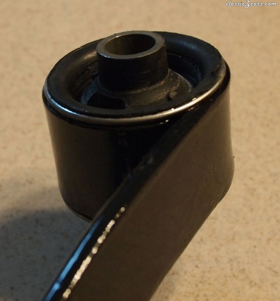
Some additional photos to support the view that the OE design for the MB mount insulators is 'special'...
.jpg.11c2748820695253059dde8cebaa899a.jpg)
-
Consider these points: The rubber in the OE bushing is softer than polyurethane The OE bushing design uses a voided core. The poly bushing is solid. The OE design for the MB mount uses not just the main bush, but also special rubber-faced end washers with a ribbed design. The aftermarket poly bush set-up uses plain steel washers. If you go with the poly bushings, they should locate the MB just fine. However, you'll probably experience more 'gear noise' coming through into the cabin. More noticeable under highway cruise conditions than around town, I would expect. Impossible to say just how much more until you try it. If you do, let us all know how it works out.
-
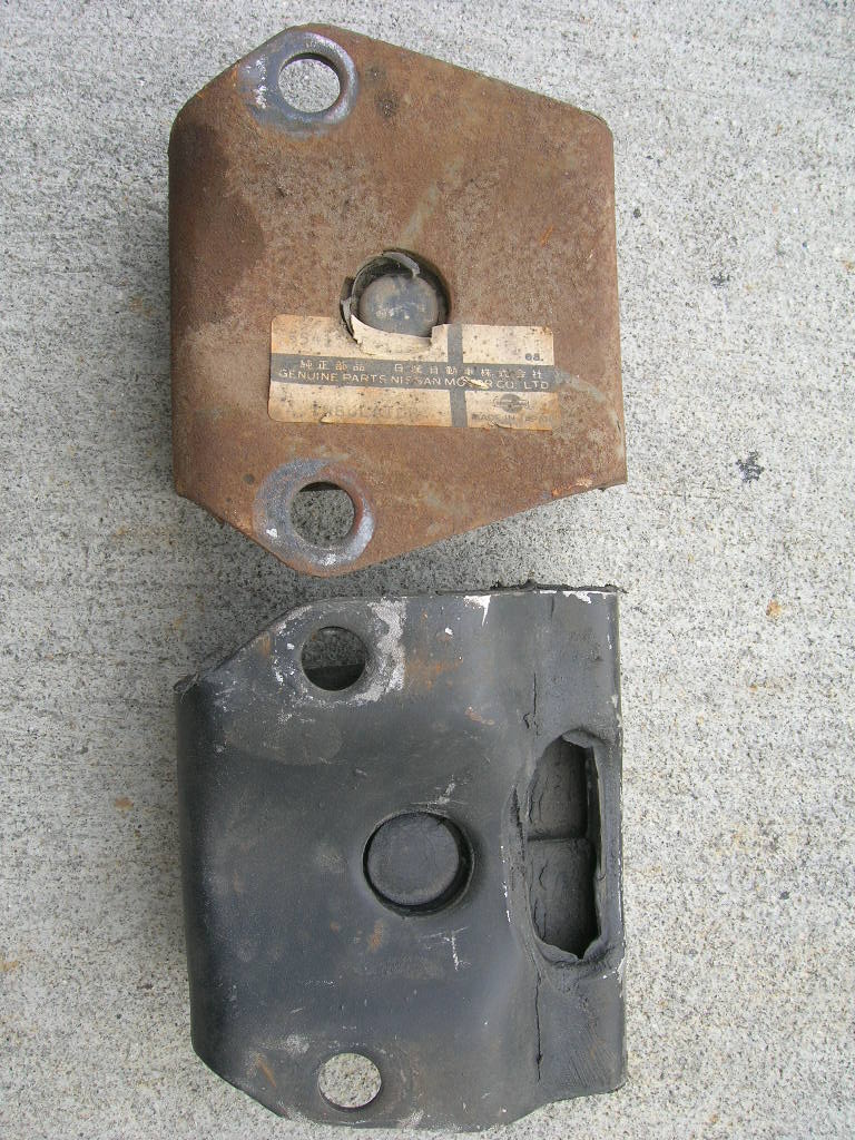
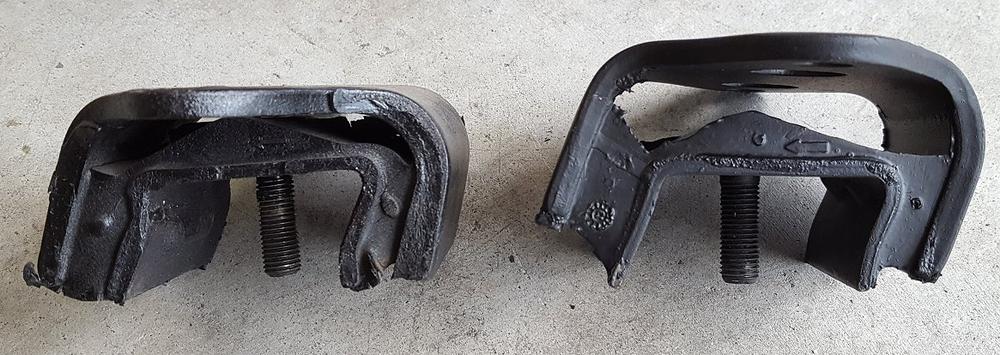
Here's another photo that I forgot to post yesterday that illustrates in pretty dramatic fashion how this insulator can collapse with age. Not surprising, given that the cross-section of the rubber core necks down to what looks like only 1/8" in width... (As before, my apologies for not being able to credit the owner of this photo.) If you go back and look at Photos #1 and #2 of my earlier post, you can see how the later-style insulator's design changed so as to significantly increase the width-wise dimension of the rubber block at the front. Perhaps this was an effort to reduce the insulator's vertical compliance. The crest built into the top of the rubber block indicates that insulator was obviously designed to bottom out. Still, it doesn't look like you'll be doing this insulator any favours, long term, if you use the diff casing as your rear jacking point. @HardwayOn a related point, Hardway's recent post in which he stuffed coolant hose into the insulator opening to (successfully) cure a diff 'clunk' issue suggests that his front insulator is now operating in a permanently bottomed-out condition. Waiting to hear whether he reports any significant increase in gear noise coming into the cabin as a result. If he doesn't, then that 'stuffing' fix may make replacement of a collapsed front insulator a non-issue.
-
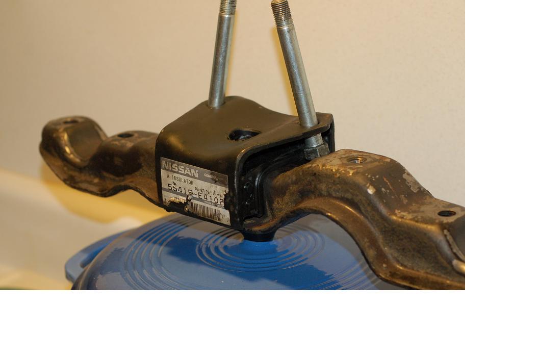
FWIW, there's a vendor in Japan currently offering the 240Z early-style insulator (55415-E4102) for low, low price of just 28,000 Yen (that would be about US$375!)
-
-
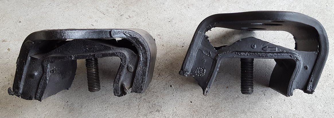
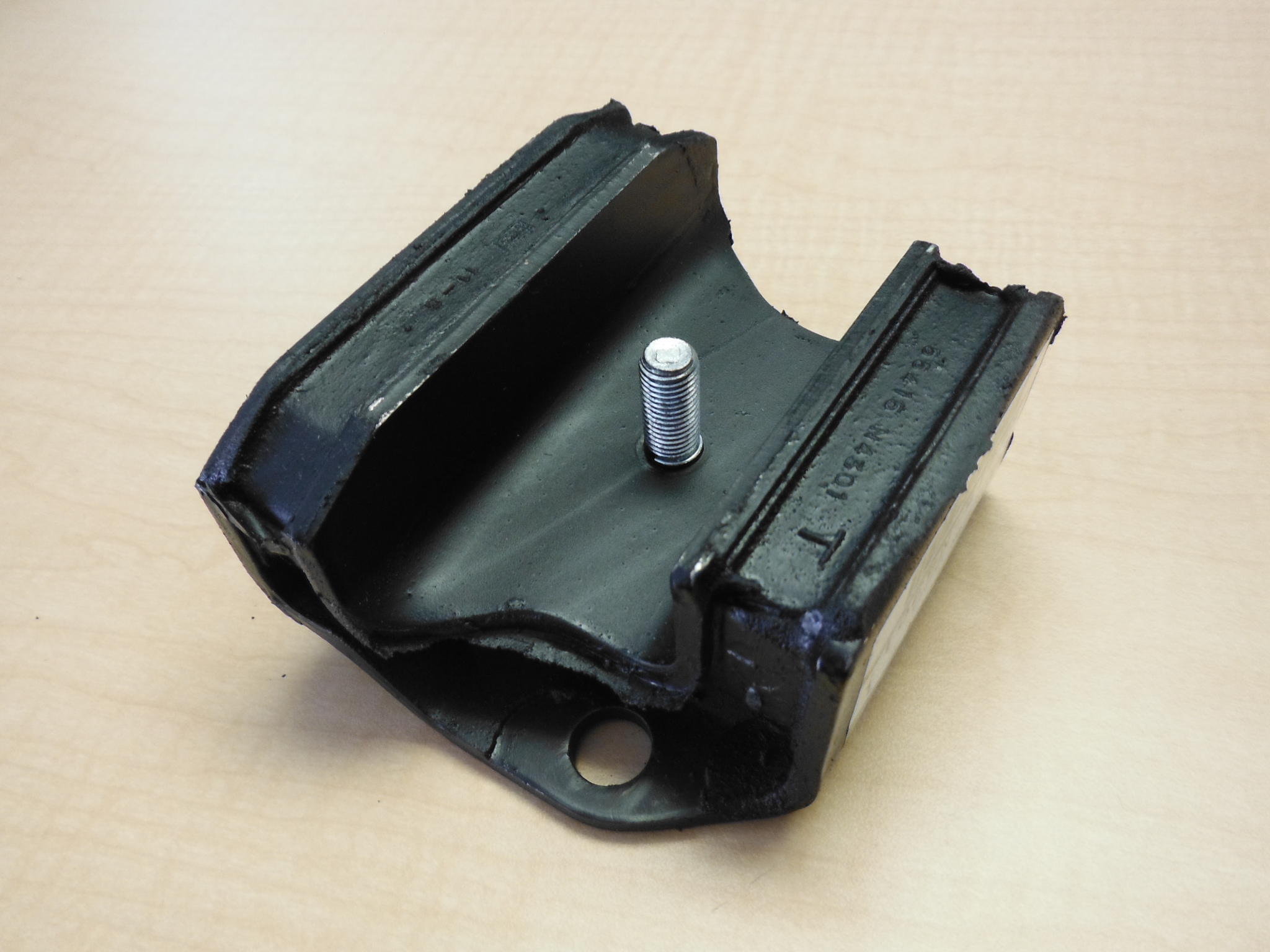
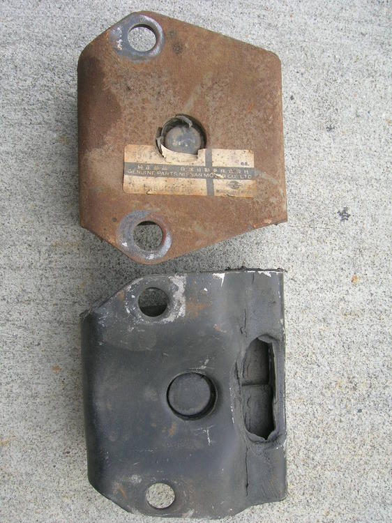
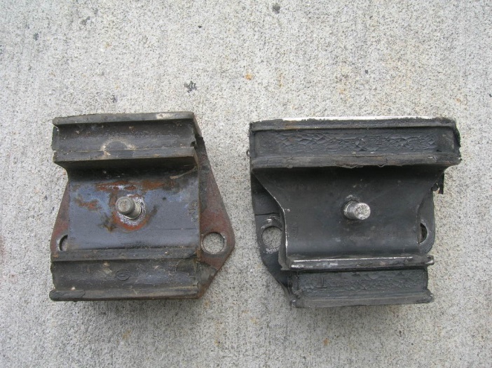
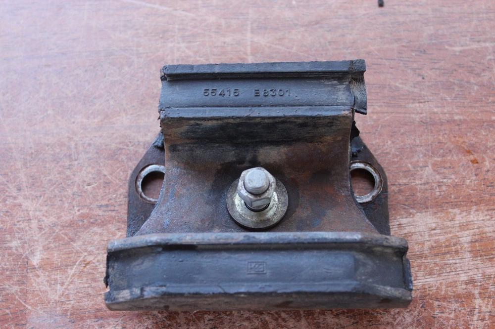
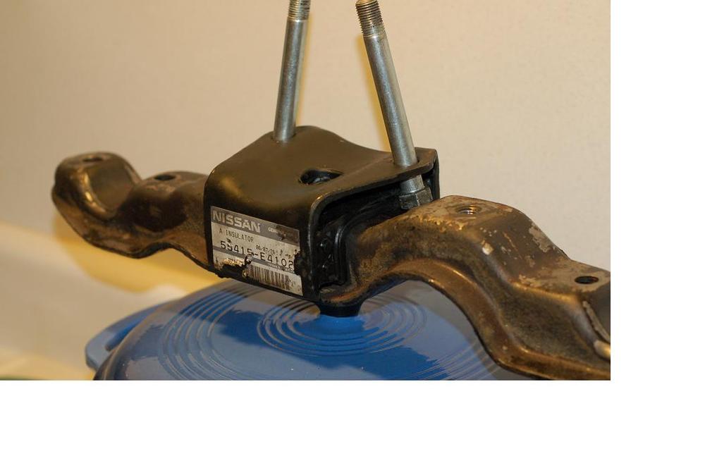
Here are some pix that I've accumulated from this site and others (apologies to the owners -- I didn't record names with photos). Picture #1 shows the top surfaces (front of car points right)... 240Z early type (55415-E4100/4101/4102) on the top, 240Z later type (55415 E8300, introduced in 7106 for the MY1972 240Z) on the bottom... x Picture #2 (below) shows the bottom surfaces (front of car points up)... early type (55415-E4102) on the left, later type (55413 E8301) on the right... x Picture #3 (below) shows a third type (55415-E8301) which -- if I read the parts manual correctly -- was offered between 7308 - 7412 (which would make it specific to the 260Z, I believe) x Picture #4 (below) shows a fourth type (55415-N4300/4301) introduced in 7501 and therefore specific to the 280Z. x Going back to Picture #1 and #2, it looks to be like the 'early' and 'later' 240Z designs, there doesn't appear to be anything different about the hole spacings/positions for the two mount bolts. The location and size of the threaded centre stud looks the same, too. The upper/outer plates have different shapes, but I don't see anything that would prevent re-shaping the contour of the later style plate if that's needed to make it fit into a Series 1. Also, the width of the inner plate's 'jaws' looks similar, early vs late, so it appears that the later style mount would fit down over the early style crossmember. I emphasize the word, 'appears', because I've never read anywhere that this can actually be done. Perhaps someone else has tried this and can comment. For possible reference, Picture #5 (below) shows the early-style insulator sitting in position on top of the matching front crossmember. BTW, I don't think there would be any need to turn the later style insulator back-to-front to make it work in Series 1 application. Again, others who've actually tried this may have a different opinion. In case you're curious, the threaded holes in the crossmember on either side of the insulator are provided to take a bolt that retains an exhaust system hanger piece.

-
I'll bet the front and rear manifold studs are snapped off too.
-
I have never seen a rippled seal like that in a hydraulic system before. Maybe someone else has, but not me. It looks more like a washer than a lip seal. Without seeing the other side (of both items), though, I won't speculate any further.
-
If you're going to install new seat covers, there's an incentive for replacing the foam at the same time. When rebuilding the bottom cushions for the seats from my 70 Z, I discovered that 'skirt' of the replacement bottom seat covers was considerably 'taller' than the stock seat covers (my replacement covers were manufactured by Distinctive Industries). I chose not to replace my original foams (they were in pretty good shape), so I ended up having to shim the underside of the bottom cushion foam with about an inch of added-in foam sheet so that the cushion would adequately fill the new seat cover. This was the only way I could bring the lower hems of the covers into proper alignment with retaining tangs on the seat frame tubes.
-
Only one U-joint in the 510's steering shaft?
-
You've managed to achieve a really nice stance for the car. The match-up of tire size/profile to wheel diameter/offset relative to the wheel openings looks spot-on. I really like those wheels, too. A refreshing change from Panasports.
-
The designs of the front insulator and the mustache bar bushings were tuned to isolate the chassis from the gear and drivetrain noise/vibration 'collected' by the diff casing. It will be interesting to see whether stuffing the front insulator's cavity with heater hose really does have an adverse effect in the form of gear howl getting into the cabin. Let us know what you discover. If a problem does set up, you might be able substitute something softer than heater hose that would be better able to meet the dual requirements of noise isolation and clunk elimination.
-
Check the U-joint. Interesting that Nissan offered u-joint rebuild parts for the 510, but did not offer them for the 240Z. If the 510 parts are NLA at Nissan, it's possible that ez-to-source Kawasaki ATV halfshaft u-joints that fit the S30 will also work for the 510. $30 complete (spider, cups, bearing needles, seals, circlips, and grease fiiting) and relatively easy to install. A 64th inch of slop in the u-joint will be greatly amplified at the steering wheel and makes straight-ahead highway driving 'more involving'.
-
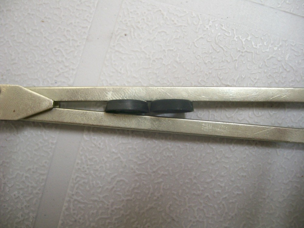
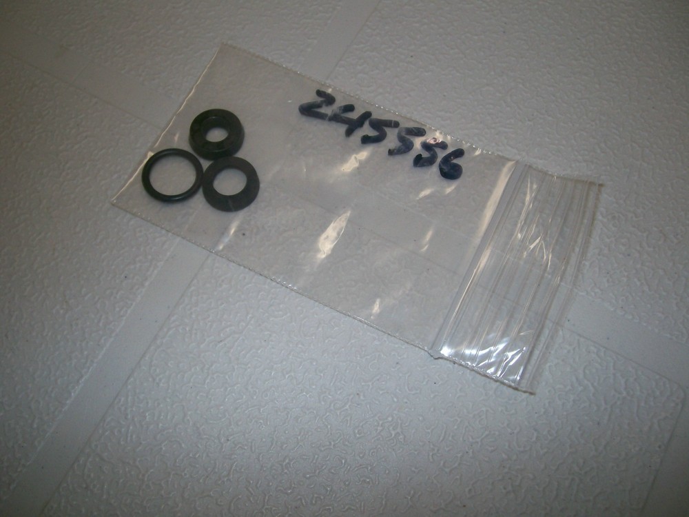
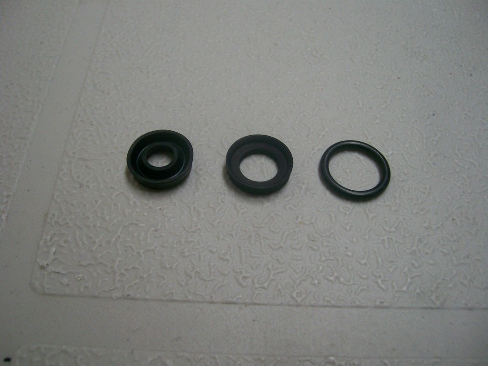
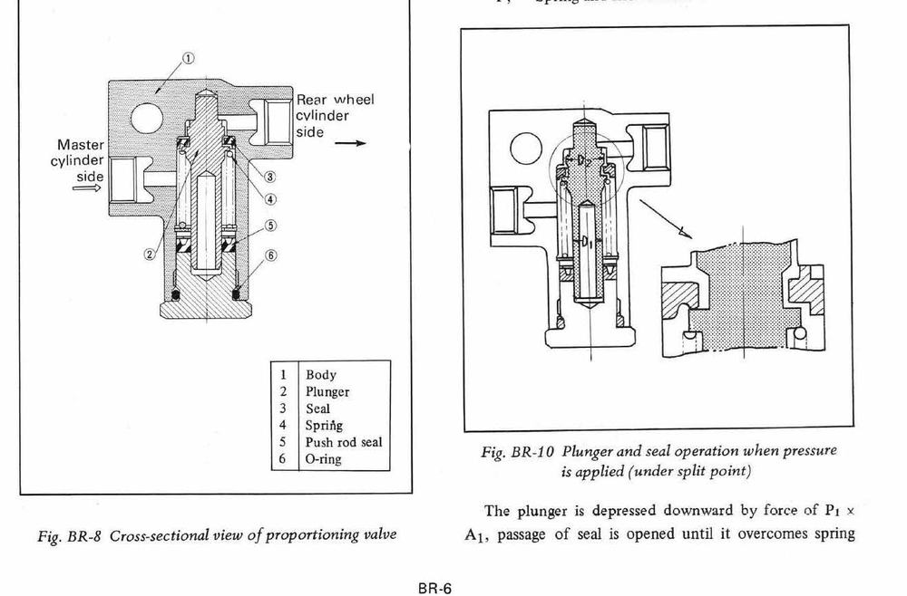
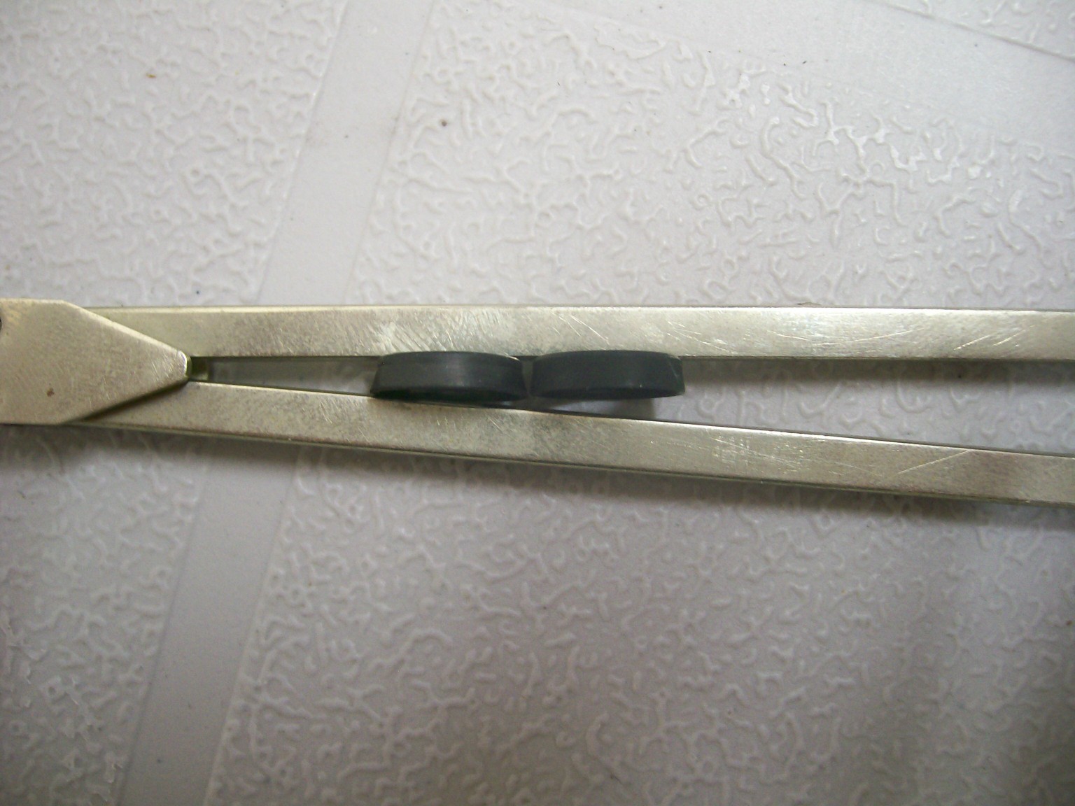
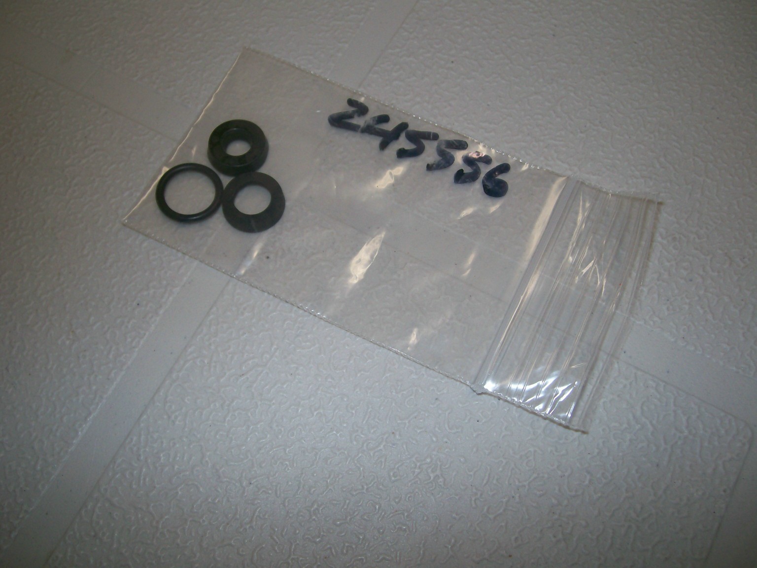
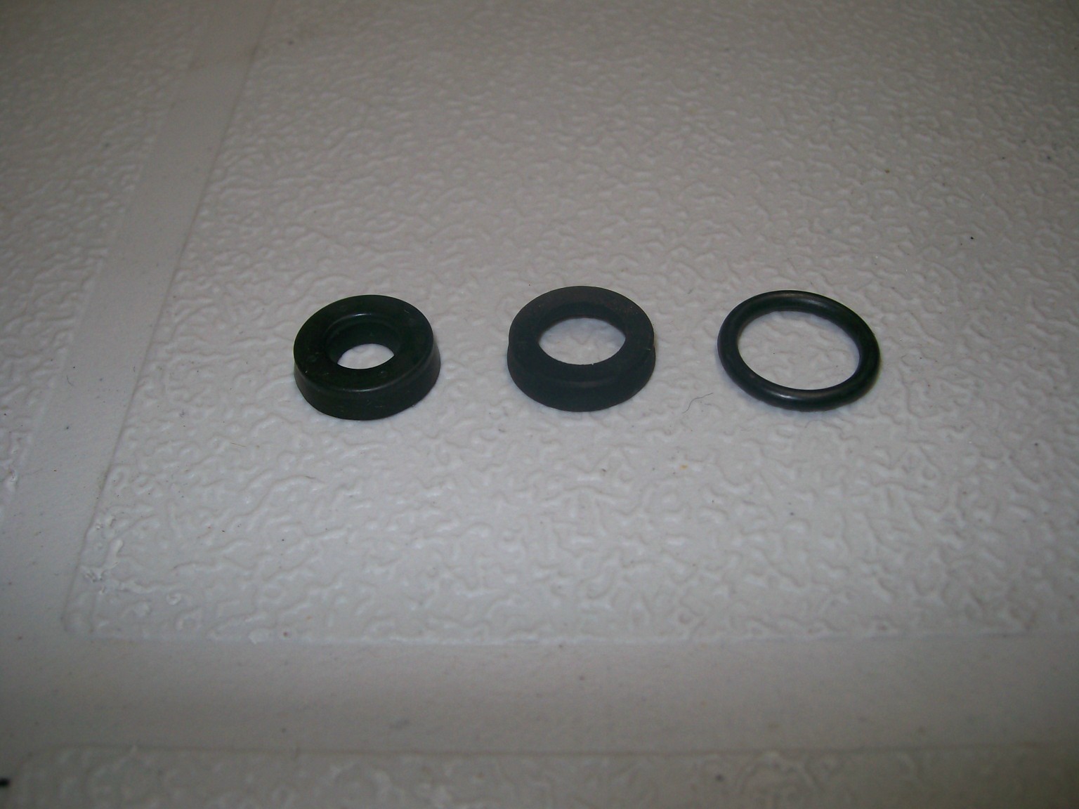
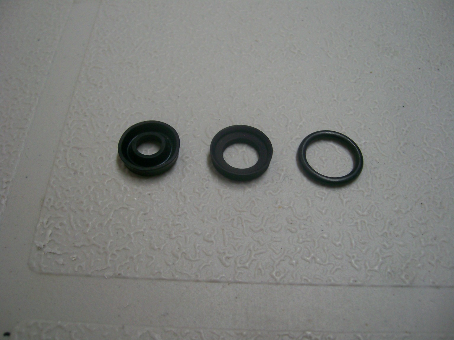
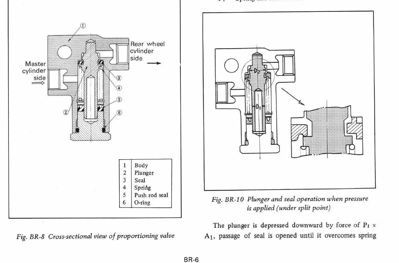
I've now received my rebuild kit from MSA and I've taken a few pictures for reference. As you'll see, the three seals in my kit are all different -- two are lip seals, the third is an O-ring. One of the lip seals (the one on the left in my pix) is lipped on both the inner and outer circumference. The other (in the centre) is lipped on the outer circumference only. Both are about the same in height. The seal on the left with the inner & outer lips is pretty clearly Item 5 in FSM diagram BR-8. By default, that means that the single-lip seal in the centre has to be Item 3. Obviously, placing them in the right locations and getting each one correctly oriented (lips face inboard, flat sides face outboard) is going to be critical to making the valve work properly. I continue to be confused by the way the upper seal (Item 3) is depicted in FSM diagram BR-9. The shape of the seal's section on the left makes sense. However, the sectional shape on the right looks like a completely different seal! Am I missing something here?