Namerow
Community Member
-
Joined
-
Last visited
Everything posted by Namerow
-
I agree that the D-I-Y strategy could come with a lot of hidden costs. It depends on the level of skill and equipment you're starting from. If you can provide the correct-sized plastic bushings, I'll bet you could get this work done quite successfully by a local machine shop for $200 - $250. If you follow this route, you'll also need to find a supplier of correct-spec replacement throttle shafts. If you check out some of your country's marque clubs, you may find someone local who does this work on a hobby-business basis (like the guy who did the on-line feature that you posted the link for). Here in the Toronto, Canada area, I know of at least two guys who provide SU re-bushing services as a hobby business (and at least one of them installs sealed roller bearings rather than bushes). If you go with the well-respected Z-Therapy in the USA, you may want to consider just keeping your existing carbs and paying them the $200 core charge (you'll see why in a minute). This would result in an out-the-door price of $880, if I've read Z-Therapy's pricing chart correctly. Now you have to look at shipping costs. Z-Therapy's website says that they only ship internationally by way of US Postal Service . It appears from the USPS website that the largest USPS 'flat-rate' box won't work (12" x 12" x 5.5"). You'd have to go with an oversize, non-standard box. Assuming a box that measures 24" x 12" x 12" and assuming a shipped weight of 5 pounds (~ 2kg), the USPS online calculator generates a price of $73.80 for their 'economy' delivery service to Germany. Unfortunately, the fine print for shipments to Germany says that any shipment valued at over $300 requires paperwork from the shipper (meaning that the value of $900 will need to be officially declared by the Z-Therapy). Later, it says that: " Germany will not accept any Priority Mail Express International or Priority Mail International insured item valued at more than $500. Items valued at more than $500 will be returned to sender. " So you would have to use the USPS premium 'Global Express Guaranteed' service (3-day delivery). For this service, the USPS online calculator generates a base shipping price of $195 for the same 24" x 12" x 12" / 5-pound box. Add at least $10 for insurance. Note that I didn't read all the fine print associated with this type of service. You should. Z-Therapy will probably add a markup to the USPS shipping cost to cover their in-house packaging and handling costs. I'm going to guess that might be $50. You'll need to confirm this with them. When the USPS package arrives in Germany, you'll have to pay customs duties (I'm going to guess 10% on $880) and perhaps/probably your national VAT too (another guess: 15%). You'll also be paying the hidden costs that your credit card vendor builds into the transaction by way of skewed currency exchange rates. Add another 2.5% to the ($880 + $195 +$50) shipped price. Call it $25. So: If my estimates are reasonably correct and I got my math right, it's going to cost you about US$1,400 to have a pair of Z-Therapy Hitachi-SU's delivered to your local post office outlet and with all local customs/sales taxes paid.
-
The author of that linked re-build article really takes SU to task for the use of a brass shaft with brass bearings. The Hitachi-SU's in the Z use chrome-plated throttle shafts. Good idea... but they still wear (first the chrome plating wears off the shaft, then the shaft itself starts to wear). The load on the shaft generated by air-pressure loading on the throttle plate under closed and part-throttle conditions must be huge. There should be little difficulty in finding a source for appropriate bushes or bearings. For inspiration, have a look at the Boston Gear catalogue, using this link: http://www.bostongear.com/products/bearings/molded.html Note that some SU carb rebuilders replace the OE bushes with seal-equipped roller bearings. Others (like your author) replace them with either new bronze bushes (oil-impregnated type preferred... ref. 'Oilite') or with an engineered plastic (like Delrin). If you decide to go with plastic, make sure the type you use is gasoline and ethanol-resistant. The roller bearing strategy is claimed to provide smoother action coming off Idle (where the plate and shaft loading is highest) -- and it undoubtedly does. How much so, I can't say. You'd need to ask people who've experienced both the bushing set-up and the bearing set-up, back-to-back.
-
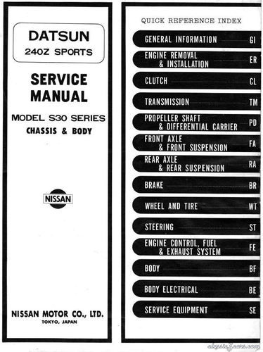 This is a great post by CanTechZ. Almost as good as having the real thing in print version. Actually, maybe better -- this .pdf is so clear that it can probably be optically scanned to generate searchable text.
- 3 comments
- 1 review
-
If you get stuck, another good cable source might be an aircraft maintenance shop at a local airport. Or an online aviation products supplier, like Aircraft Spruce... www.aircraftspruce.com
-
I hope this Graingers order turns out well for you, but be sure to take a measurement caliper with you to the store so that you can check the wire's actual diameter before you complete the purchase. If the '0.051' wire turns out to be wildly undersized (and it might), don't count on the next box labeled '0.051' being any different. If you encounter this problem, I suggest you order a replacement box that's the next available size down -- probably '0.049' -- and hope for a better match between 'as labelled' vs. 'actual'. FWIW, remember that wire's bending resistance is proportional to the wire's x-sectional area (I.e. diameter squared), so an 0.049" wire is still going to be more than 50% more resistant to bending than the 0.039" (1.0mm) wire that Nissan used in the Series 1 control cables. For the sheathing, I think you'll get good results if you can find something with an inside diameter that's somewhere between 1.25 to 1.5 times the diameter of your wire. Also, make sure that the wall thickness isn't too skinny (I think that bicycle cable has steel-wound 'armoured' reinforcement, so it should be just fine... provided the inside diameter isn't too tight on the wire). If the sheathing you find isn't armoured, it looks like a wall thickness of about 1/16" should be about right. As you put everything back together, the 'stick-out' lengths* for the sheathing should be between 1/8"and 1/4" for the three flap control cables and about 7/16" for the water valve control cable (* 'stick-out' means how far the sheathing projects beyond the edge of the pinch clamp). You may need to play with these settings a bit to ensure good action and no interference with the flap/valve control lever. My suspicion, though, is that the system will work just fine without too much fiddling, provided that all the flaps/cables/levers and the water valve are lubed and operating freely. It's only when the parts start to stick that the wire gets overloaded.
-
I was able to restore my car's corroded heater valve to good operating condition by soaking it for a couple of days in a household-type 'de-liming' liquid (same stuff that's used for cleaning up kettles and coffee-makers). The product I used is called 'C-L-R' (stands for, calcium-lime-rust, IIRC). Probably not available in the UK, but I'm sure you'll be able to find a similar product without much fuss. These heater valves are relatively bullet-proof... except for the little seal where the control rod exits the main valve body. If you take the valve out of the car to refurbish it, make sure you pressure-test before you refit it. If the little seal leaks, you're probably best to buy a complete replacement valve. To pressure test, cut a length of skinny bicycle inner tube, complete with the valve stem. Seal off one end (clamp it), then clamp the other end over a short length of heater hose. Then clamp the heater hose onto one of the heater valve's ports. Put your thumb over the other port, then pump some air into the inner tube. If you hear air escaping through the control rod's seal, it's time to order a new heater valve.
-
-
-
Thanks, CanTechZ. That scan quality is excellent. So much better than the version that's currently available. If you're able to find the time to scan and upload the entire manual, all of us CZCC members will be in your debt. BTW, how did you acquire your copy? e-Bay? Dealership connections?
-
-
Thanks. I had a look and discovered that this seller is offering CD's of the manual, rather than print copies (I should have known, given the asking price). They're both informative and confusing, aren't they? I can certainly see the incentive for a service department wanting separate volumes. I single-bound Body/Chassis + Engine manual must have weighed 5 pounds! Throw in the Electrical/Dash/Instruments supplement and you've got a substantial amount of paper on your hands. Thanks for the offer. I get by with my downloaded 'Blue' version. Where a photo is too fuzzy to make out details, I find that in many cases the very same photo or diagram appears in the '72 FSM. I've got the British Autopress and Haynes manuals for backup. My reason for bringing up the subject is just that the 'collector' in me has always wondered why a '1970' FSM has never seemed to be available.
-
Thanks, Mike. I already have this and thought it to be the 1971 FSM. Hard to tell because the person who scanned it didn't scan the cover. Is this, in fact, the first Z FSM, issued for the 70 Z and then held over as also applicable to the 71? Or is it the 71 FSM, with a scanned version of the 70 FSM still n/available?
-
-
Hard to keep up with all the new chemicals and materials that are appearing on the market! These strippable films make me wonder whether spray-on-paint jobs (i.e. traditional exterior finish coats @ $5K to $15K final cost) will disappear.
-
More on the OE cable sheathing... Early-type sheathing has an OD of 0.18" and fits a 0.039" (1.0mm) wire. Later-type sheathing has an OD of 0.19" and fits a 0.051" (1.3mm) wire. BTW, the Z's carb choke cable wire measures as 0.055" (1.4mm).
-
I bought my wire over the counter from the local outlet of Canada's equivalent of McMaster-Carr (Acklands-Grainger). They stock several different gauges... https://www.acklandsgrainger.com/en/product/WIRE-MUSIC-22-049-1LB-COIL/_/R-CMG66MW049 Important to note that the Series 1 system uses not only different-size wire but also different-size cable sheathing in comparison with the later, revised system. I'll fill you in on that later. Out of time right now.
-
I just read that bulletin. It does zero in on bent cables associated with the 'heater-vent control flap', saying that the flap may stick because of 'excess adhesive' (the two big control control flaps have skinned-foam padding bonded to both sides to help them seal better and also to help prevent unseemly 'clanging' noises when the flap snaps shut). The TSB recommends that the technician fab their own replacement cable using 0.049" music wire (1.25mm). They offer this interesting recommendation for forming a modified 'device-end' bend... It seems that it's only intended to keep an overloaded cable from slipping through the engagement hole in the control lever arm, rather than a way of offering some compliance. Personally, I wouldn't get too excited over the need to buy 'factory original' cables. It's only wire. Buy some and bend it to shape. I pre-tested the 'oversize' 1,3mm wire in the Series 1 plastic sheathing and it works just fine. Not even a whiff of binding. So now I'm running the 'big' 1.3mm cable, complete with my DIY, custom-bent Series 1-style bent (no loops) ends while preserving the original Series 1 cable sheathing. Although the system hasn't been put back in the car yet for final testing, I'm confident it's going to work just fine. Everything's been clean and lubed, all the flap pivots ditto, and the 1.3mm cables are 70% bigger in cross-sectional area than the original 1.0mm cables, so they're going to be a lot stronger. The loop-and-pin design of the later system is definitely a better mechanical design, but I prefer the 'flawed design integrity' of the older system.
-
Hmmm... The diagram in the FSM Supplement suggests we both may be wrong. Here's the FSM diagram (Series 1) and parts names... Lower Right - 41 - Temperature Lower Left - 42 - Room-Defrost Top Right - 43 - Compartment Air Top Left - 44 - Hot Water Valve Maybe I'm mis-reading the number labeling on the diagram, but I think it's wrong (or the parts numbering has been jumbled in the parts name list (not shown here). The Owners Manual clearly identifies the control knob functions as: Top Knob - 'Air flow control for heating or ventilating' Middle Knob - 'Air temperature control' Bottom Knob - 'Air flow control for room heating or defrosting'. Therefore, I don't understand how the FSM diagram manages to assign Cable #44 ('Hot Water Valve') to the top lever. Perhaps someone else can comment. Which cables go where?
-
Don't forget to put a chipmunk screen over that cowl drain tube!
-
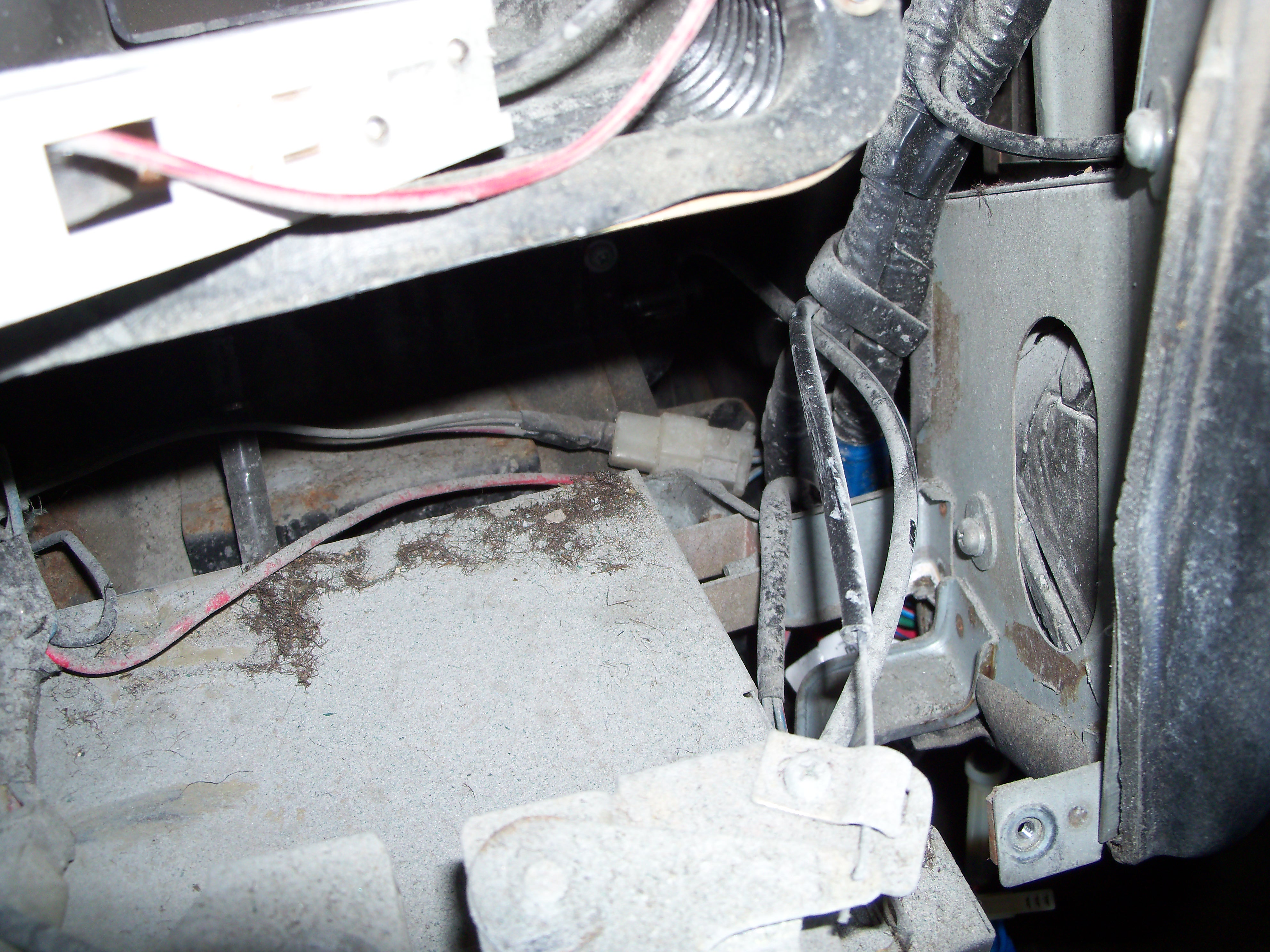
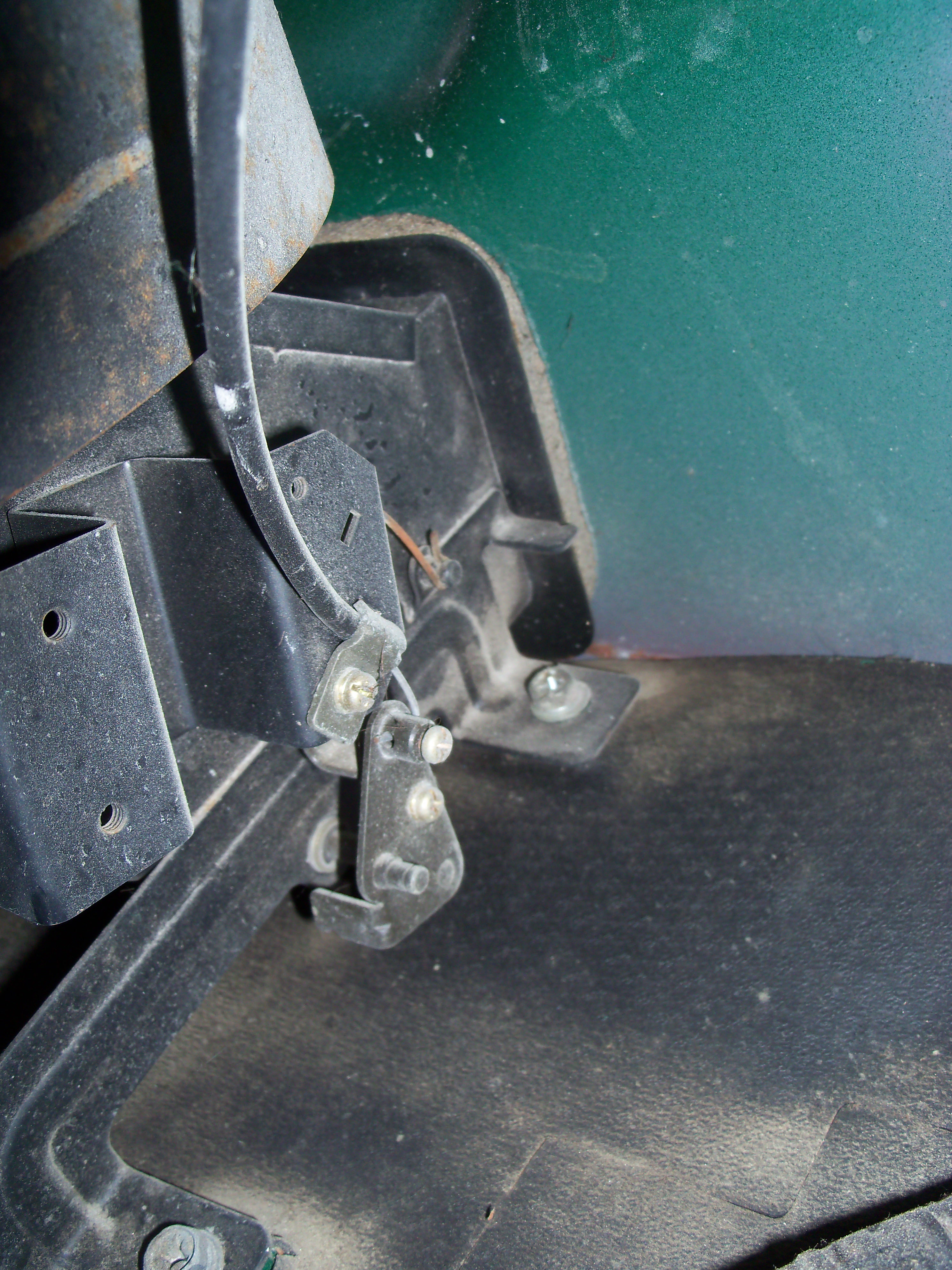
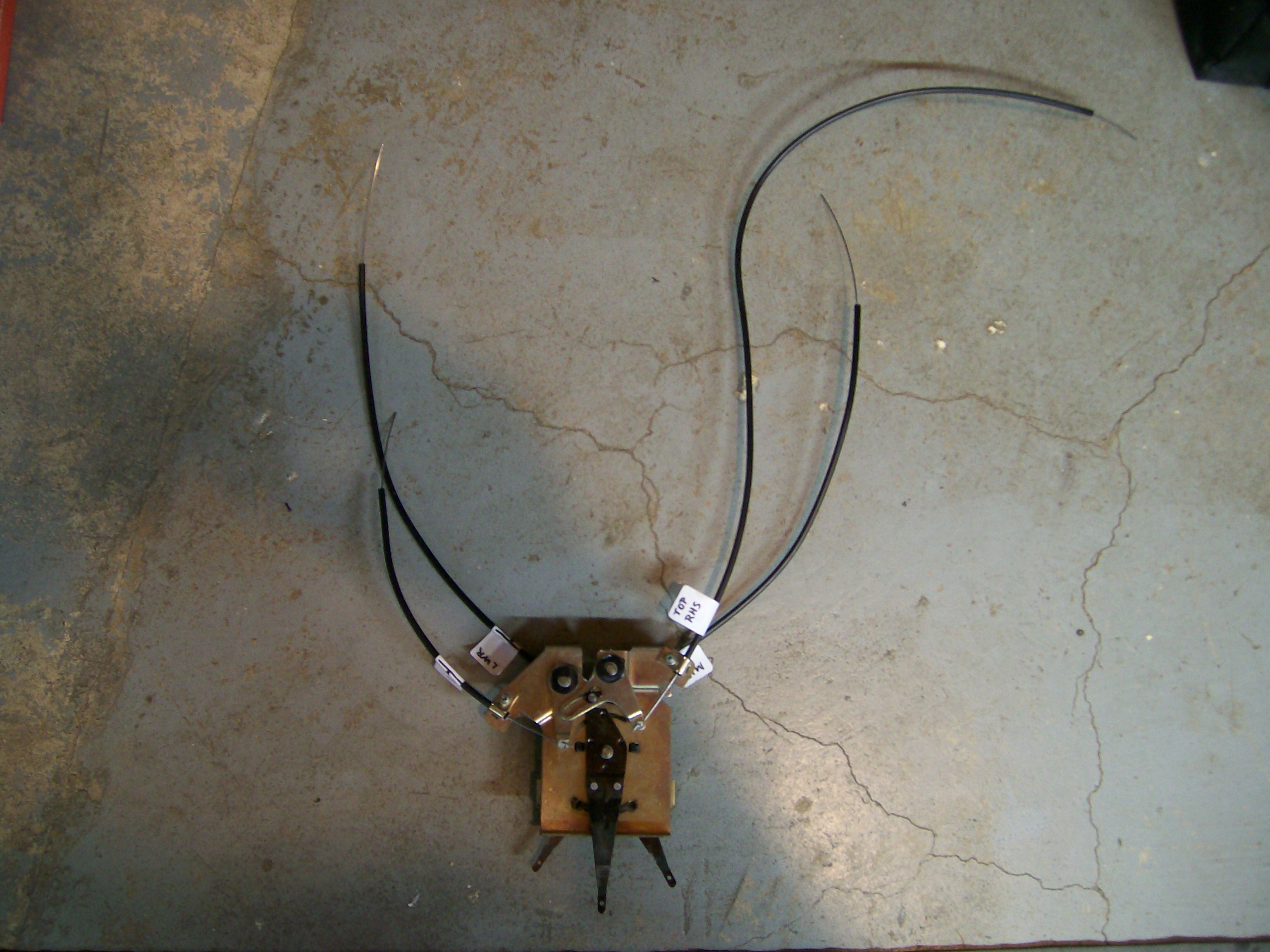
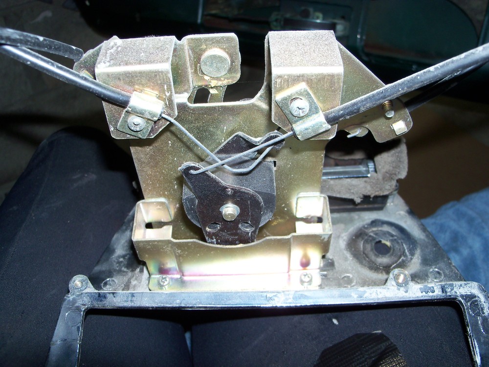
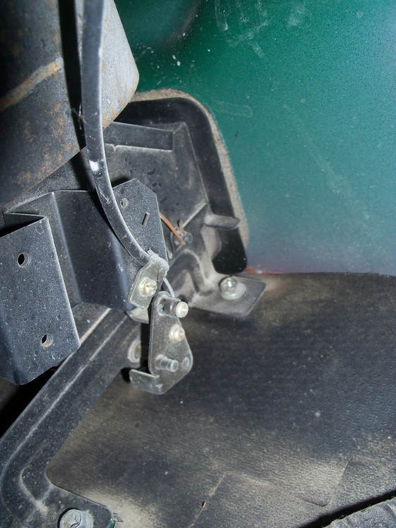
A few thoughts: Is there any chance that the previous owner replaced this cable with non-tempered wire? If so, it will remain prone to bending like this. How easy has it been for you to straighten the wire previously? If your answer is, 'easy', then my level of suspicion would increase. Like Zed Head, I made my own replacement set of cables using tempered 'music' wire. Not a hard job, really. I formed the ends by hammering the wire to shape over the jaws of my bench vise. Even if the bent wire is made from tempered stock, the fact that it's now been bent and straightened three times at the same spot may have softened or weakened the metal at the bending point (meaning that it's pooched and will never perform properly). Metallurgists, feel free to comment. Not sure what vintage of Z you're working on, but be aware that there was an earlier style of heater control mechanism that used thinner-gauge (1.0mm) control wires. They didn't prove up to the job and tended to bend if there was any extra resistance in the system (due to corrosion, parts, interference or even, perhaps, mis-routing). The re-designed system used 1.2mm wire (along with loops rather than straight-wire-and-a-pinch-screw used to secure the device end). Note that the pictures below show the early design with the skinny control cables. A sticky control lever shouldn't cause the load on the cableto increase. The problem has to be friction or interference downstream of the control lever (or an under-spec wire). For your possible interest/amusement, here's how my Series 1 assembly looked when I took it out of the car. The culprit here was a frozen heater control valve (and an impatient driver or passenger who was clearly not happy with the cabin temperature!). x Below are the best pictures I have to show the original routing of the control cables. These were taken as the assembly was being removed from the car as part of stripping the interior. Unfortunately, for the cable that you're having trouble with they only show the end sections and not much of the middle part (notice that the device end of the cable where it mounts to the flap lever doesn't look to happy -- which may help to explain why the factory revised the device ends of the cables to a loop-over-peg design). x Looking in ^ Looking up ^ This final picture, showing the complete assembly lying on the floor of my workshop, may give you some additional clues about the cable routing.


-
Agree with Mark on this easy-to-do-and-reversible experiment. That said, I continue to believe that the evidence points to the cause of the problem being heat conducted into the fuel in the delivery/return lines by way of the fuel rail assy's mounting straps (which, don't forget, connect to the cylinder head -- arguably the second-hottest piece of metal under the hood). The problem certainly doesn't seem to be convectional heat transfer caused by hot underhood air temps. If that were the case, the factory 'fix' of adding insulation along the steel lines should have cured the issue (and it apparently didn't). I don't think that the success of Jeff's strategy of replacing the OE steel with rubber hose comes from the better insulation qualities of the rubber walls against convectional heat transfer from the air. Instead, I think it succeeded because either the rubber hose or Jeff's hose mounting scheme -- or a combination of the two factors -- provided a better barrier against heat being conducted from hot engine parts into the fuel in the lines. BTW, I find it interesting the the E-Type Jag's (fitted with triple SU's and probably generating equally-high underhood temps) didn't seem to suffer from fuel starvation problems -- even though they were notorious for high coolant temps and overheating. Anybody know how the E-Jag's fuel lines are mounted? So, JAlex: In the absence of a bulletproof technical diagnosis (we still don't have one, after 8 pages of input), you're just going to have to experiment in a methodical way until you/we find either the cause or a solution (preferably both). Try Mark's suggestion and see what happens. Then report back to us here with your findings. Until you do that, you're just going to get more conjecture (mine included) about possible causes and possible cures. Note that there is no over-the-counter 'kit' that you can buy to follow Mark's suggestion, so don't ask us for parts numbers or suppliers' names. Here's what I would do. Buy a couple of lengths of automotive-spec fuel line (1/4" for the supply hose, 3/16" for the return hose -- buy 'traditional' low-pressure rather than 'EFI' high-pressure hose). Also buy a length of 1/2"-width steel 'strapping' (plumbing supply shop -- comes in a roll). Use the existing steel fuel lines to provide mounting points for the new hoses. Use automotive hose clamps (screw-type) to mount the hoses to the steel lines. You'll need T-fittings to split the delivery hose into two paths (one for the front, one for the rear carb). Same goes for the return hose. Be tidy with the hose mountings and routings. Keep the hoses away from moving parts (like the fan and the throttle linkage) and off of hot parts (like the exhaust manifold). Be sure that the clamps at the fuel pump, carburetor, and 'T' connections are tight. Be sure that the new hoses won't snag the throttle linkage. Once you've got your new 'experimental' fuel hose set-up in place, post a few pictures here so the members can warn you if you've done anything wrong. If you get the 'all clear', the next step will be starting the engine and doing final checks before you try it out on the road. IMPORTANT: If you are in any way concerned about your ability to do this type of work safely and successfully on your own, do not attempt it. Instead, get a licensed mechanic to do it for you.
-
I watched that auction and consider the result to be an anomaly. It seemed to capture and build on the enthusiasm of a couple of guys who thought is was, 'a great build'. Which it was. However, on most days a modified Z only draws contempt from the BaT audience. High praise and high bids are reserved for mint examples. So put that paint brush and masking tape away.
-
Nice photos. The latter two raise once again three of the ongoing Z 'style' debates: stock vs lowered ride heights; over-under vs. single exhaust tips, and; plain bumper vs. over-riders. (If anyone asks, there is no correct answer.)
-
As someone from the era pointed out, they were just used-up, well-past-their-prime race cars at the time. He even used it in the winter to take his kids to school! If you want a really good read about Mason's car addiction, find his comments in "Into The Red" (a wonderful purchase, if you can find a copy) about owning one of the even-fewer-built early-50's BRM V-16 grand prix cars. In the way that only a well-to-do Brit can manage, he estimated that it cost him as much per yard to drive that car, "... as laying the finest Wilton carpet".
-
 A template to make your own gaskets. 240Z HVAC Gaskets Blower Motor Fan Mounting Plate-to-Blower Housing. Created and supplied by our member @NamerowFree