


Namerow
Community Member
-
Joined
-
Last visited
Everything posted by Namerow
-
I was going to say that a manifold swap might be the easiest solution. However, it appears that the 260Z head has port sizes that are bigger than those for the 240 and smaller than those for the 280. The 260's header has a PN that's different from both the 240 and the 280, which tends to support the theory that it is a unique design (but in what ways, I don't know). Other members will know for sure if a swap can be done successfully. Is it possible for you to buy, inexpensively, the part that threads into the manifold? That would make it easier to measure the thread dia. and pitch.
-
FWIW, the OE heater valves respond very nicely to an overnight soak in CLR calcium/lime remover.
-
Come on, admit it. That's not really an office. It's a parts storage room disguised as an office so that you can keep your Z stuff in the house without your wife noticing.
-
Mike may have a point. The flat on the ferrule could be just a provision to orient the switch properly relative to the OFF-LO-MED-Hi markings. Note how the the front of the switch housing has a 'lumpy' surface that's maybe supposed to key into the mating surface of the fascia plate. Note that in his photo, Mike's switch appears to be missing a white nylon washer that's should sit between the jamb nut and the front surface of fascia. I think it's there to spead the clamping force exteted by the jamb nut over a broader surface area. Maybe a couple of small dabs of Gorilla glue on the front of the switch housing before you re-assemble against the back of the fascia?

-
More importantly, the mounting hole in the fascia (what your holding in the picture) is supposed to be slightly D-shaped, so as to match the flat that's machined onto the threaded ferrule of the switch. It looks like a PO or passenger got over-enthusiastic and torqued the control knob so hard that the 'D' was completely stripped out of the plastic. It'll will be very hard to restore the D shape to the mounting hole in fascia. But perhaps you could try grinding a D shaped hole into a fender washer (Dremel tool) and then glue the fender washer to the back of the fascia plate. Or maybe you could just solder a piece of flat sheet on the back of the washer so that it slightly overlaps the hole, thereby creating the flat that makes the hole become D-shaped. Anything you glue onto the backside of the fascia plate is going to act as a standoff for the switch housing, and that means that the shaft of the switch isn't going to stick out on the other side as much as it normally would. In other words, keep your repair materials thin. Whatever you adopt as a repair, it's going to need to be sturdy or else it won't last very long. The simple-but-expen$ive route will be to simply buy a new fascia plate.
-
I've had mixed results with computer matching. According to one paint tech I dealt with, the darker the color, the more difficult it is to get a good match. Metallic content adds to the challenge. My car came painted with an unidentified, non-stock dark green metallic, so getting a match has been a problem. I ended up asking a high-end restoration shop for help and they put me onto the specialist paint supply shop that they use. I removed one of my Z`s inspection cover panels and gave that to them to use for the paint-matching. Perhaps you can try the same approach. Find a resto shop that works with high-end customers and high-end cars, and then ask them who they use for their paint.
-
The seller said somewhere in the Q&A comments that he installed the later-style console because the original was in poor shape and a replacement was impossible* to find. * Impossible? Almost never the case. Expensive? You bet!
-
If we're lucky, this will trigger a rising tide that floats all our Z-boats If we're not lucky, it will attract a fresh horde of parts-car-quality Z's to BaT, thereby reinforcing the belief that all Z's are either victims of the J.C. Whitney catalog or just rust buckets and thus not worth more than $5K - $15K.
-
I missed the note in the write-up about the dash cap. Nothing wrong with that if it's properly done but, again, it takes the car an important step away from the 'all-original' status the has always seemed to be mandatory to get a Z's price firmly into the $30K - $40K range.
-
https://bringatrailer.com/listing/1971-datsun-240z-35/ I'm surprised that there's been no commentary so far on this car. It brought a ton of attention during the auction. It also sold at a price that -- I think -- lies well above the curve (not that that's a bad thing). Almost $40,000! The part that really surprised me was that previous high-dollar Z sales (i.e. those in the $30K+ range) seemed to be based on extreme originality. This car didn't have that. While it was very free of rust and had been very nicely restored and had a nice, shiny-new paint job, there were a number of details that weren't OE (most notably, the ZX 5-speed transmission - also: Konig aftermarket wheels, lowering kit, PU bushing kit, overside front roll bar, black-crackle paint in the engine compartment, aftermarket aluminum rad, mishmash of engine hose types, screwed-in-place bare-metal replacement battery mounting frame). In addition, it was a crossover car that had a mixture of Series 1 (angled halfshafts, metal engine fan) and Series 2 (seats, steering wheel, console, no-vent hatch, etc). Don't get me wrong. I wish that my car was this nice. But this one seemed to violate some of the accepted rules for when a Z will move in value out of the low-mid 20's and into the 30's (and the very high 30's in this case). Does this sale mark the beginning of a new era of S30 pricing, or did the car just show up in the right place at the right time?
-
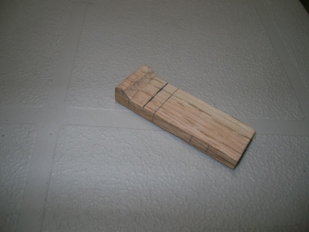
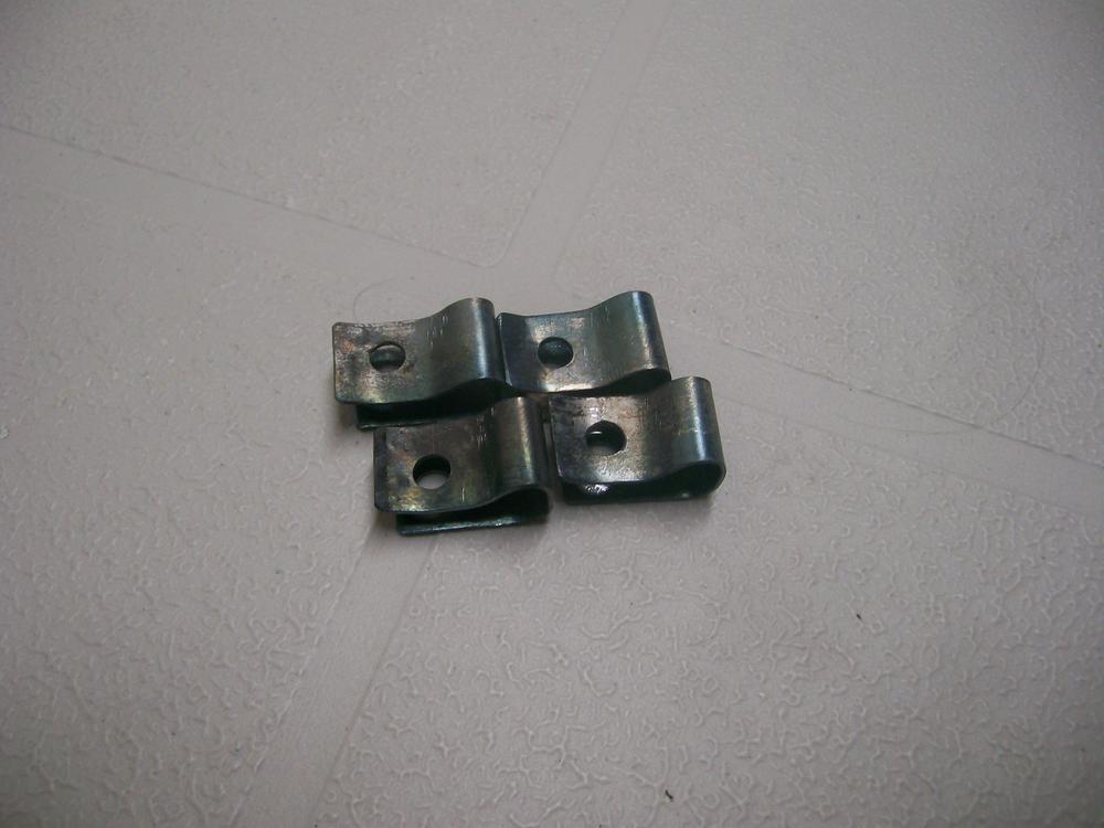
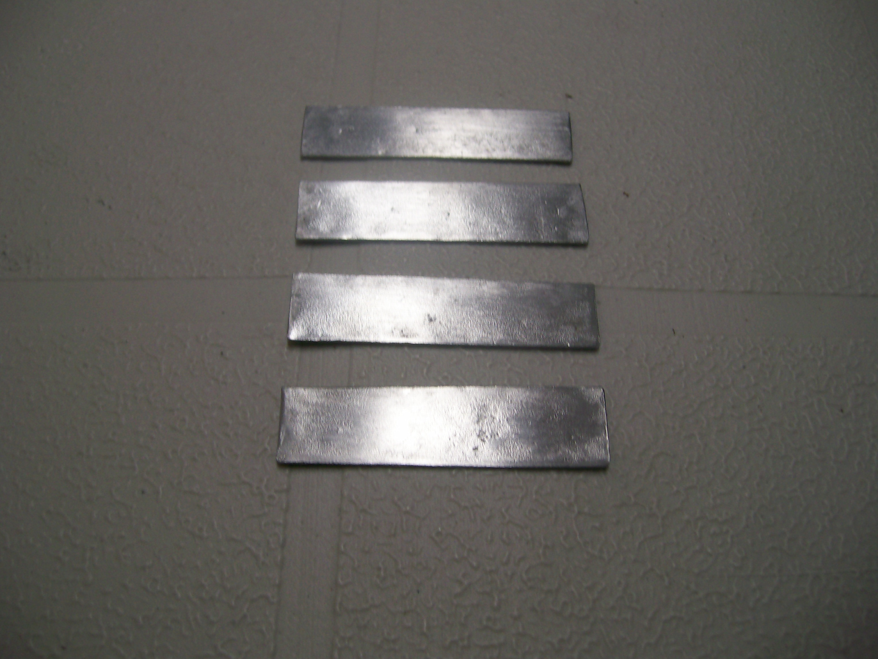
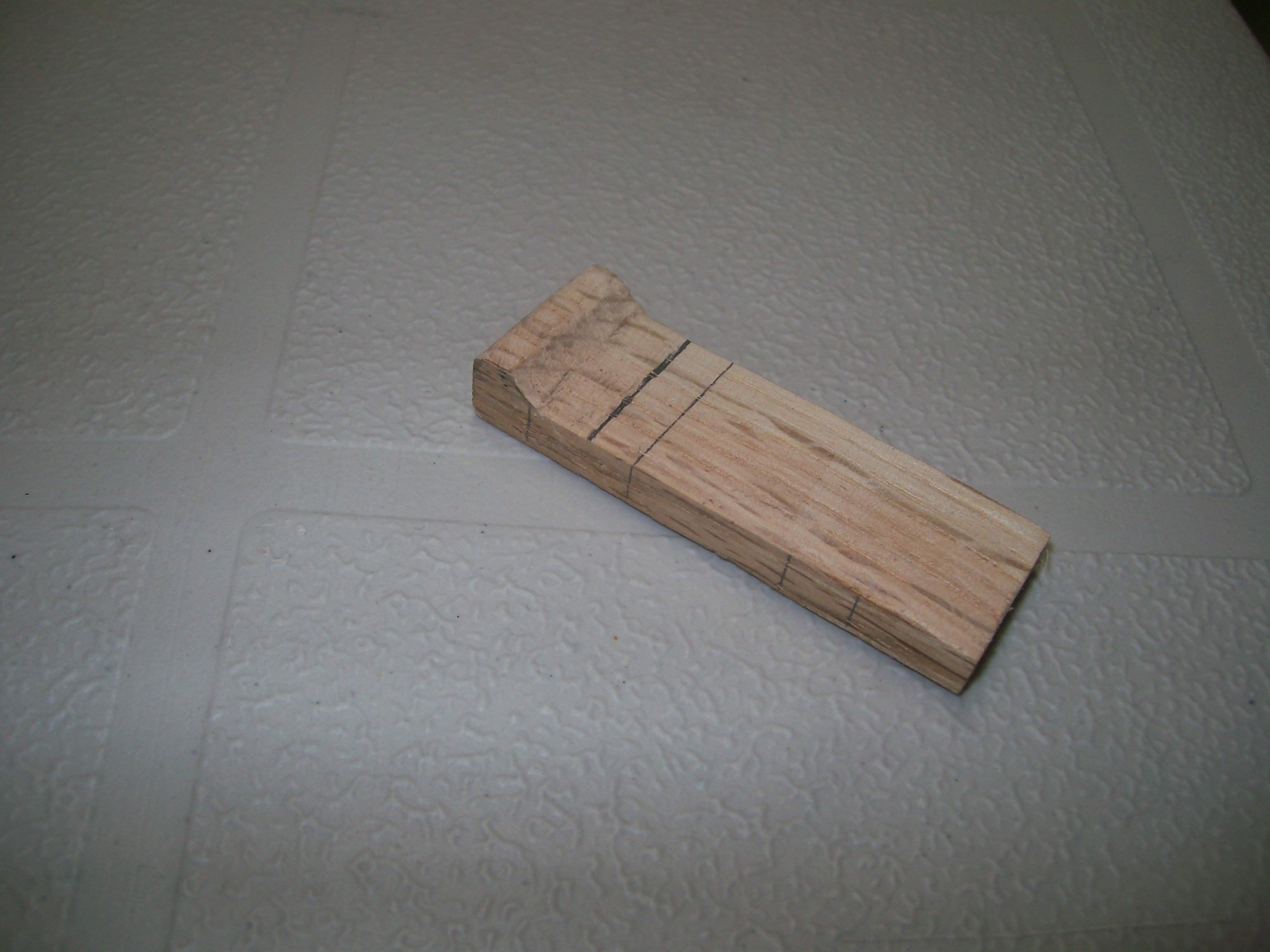
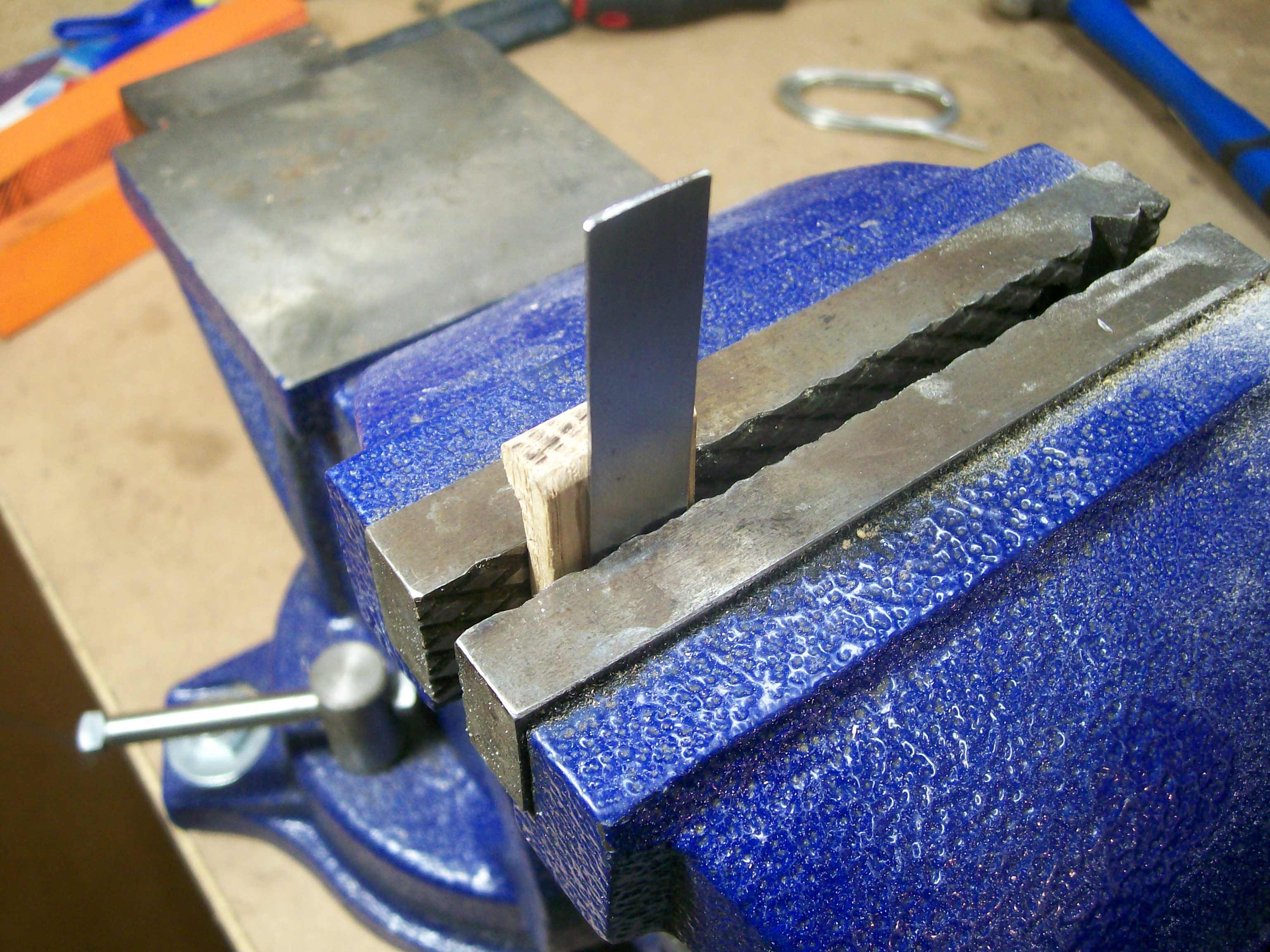
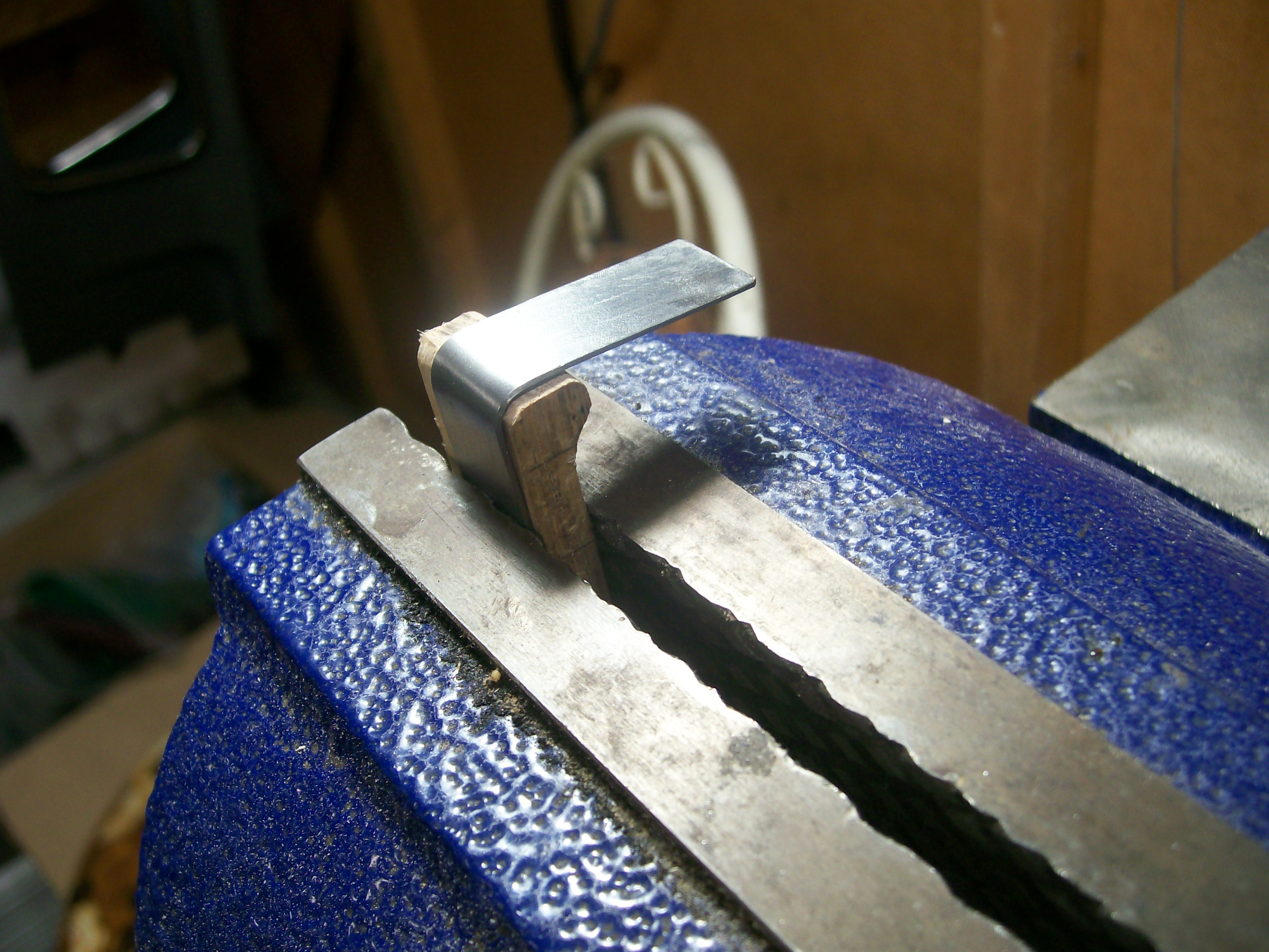
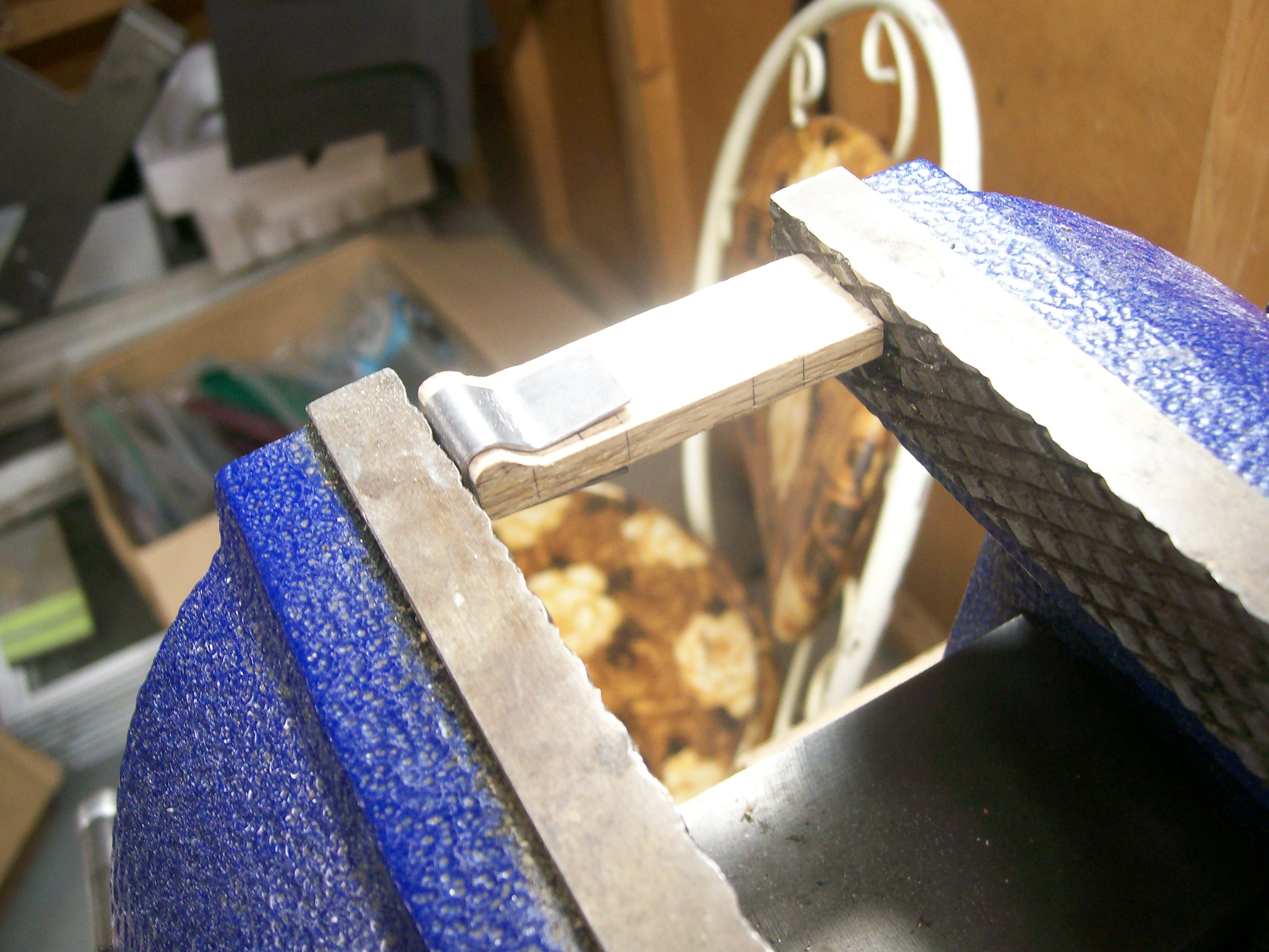
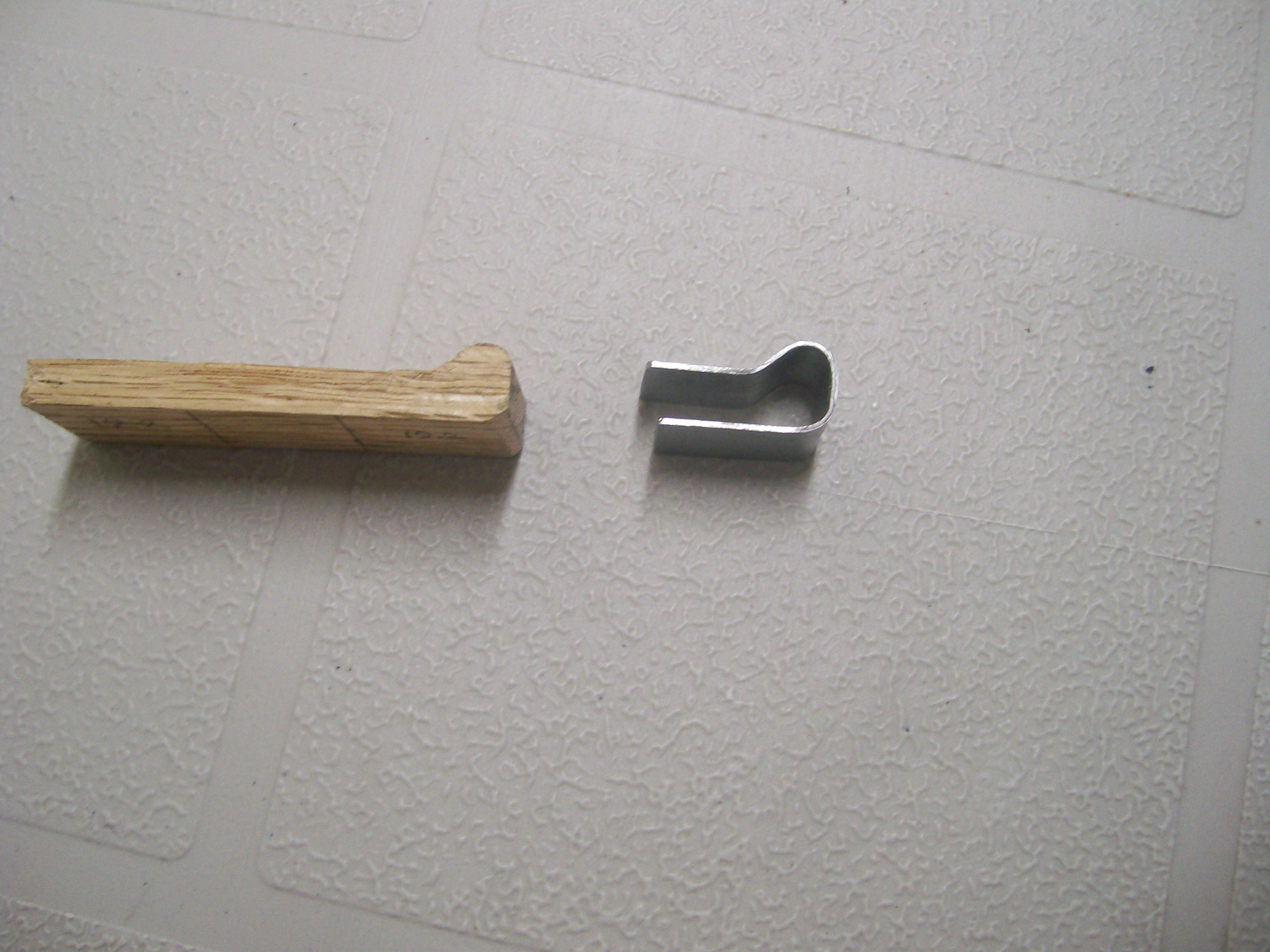
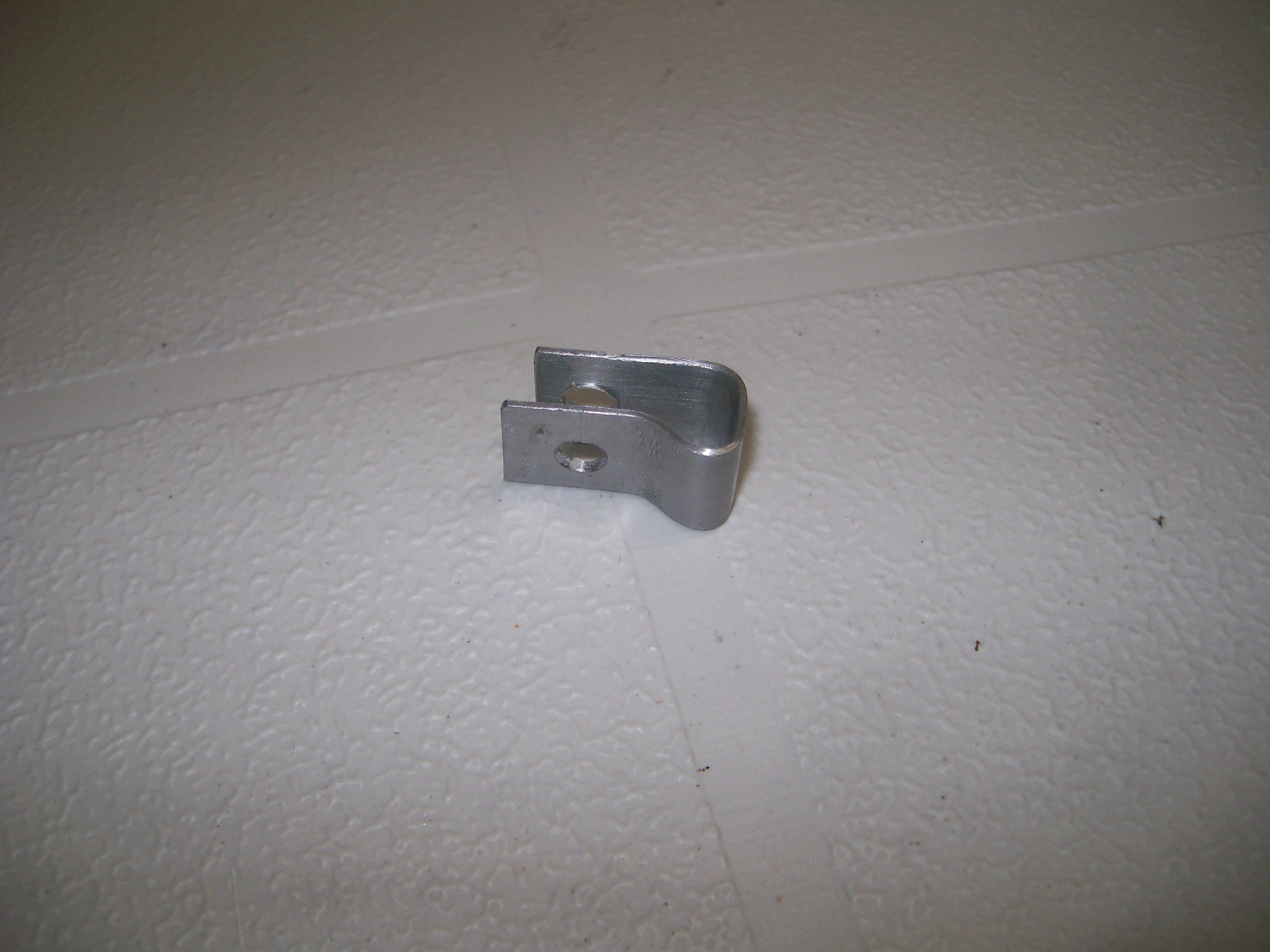
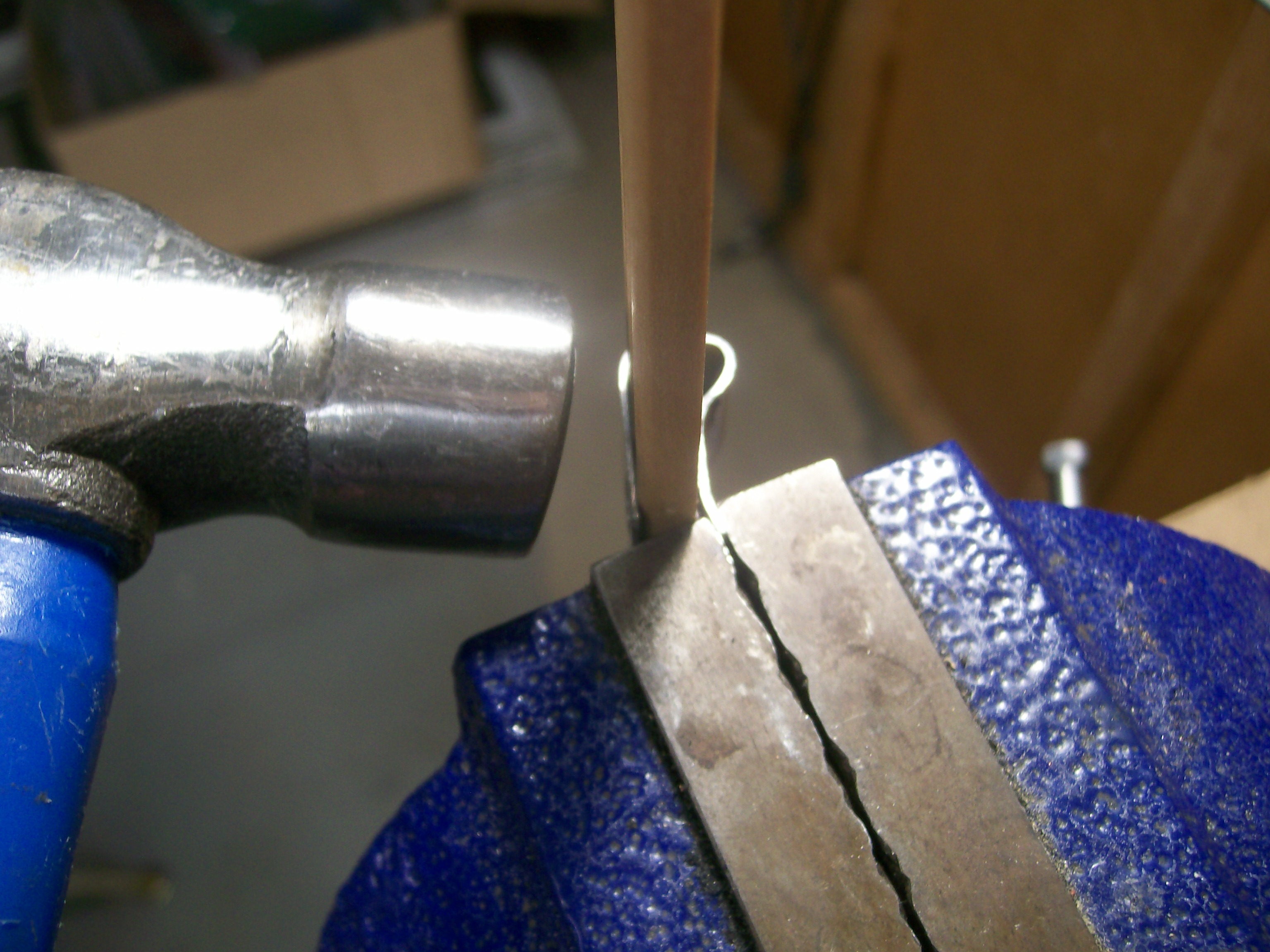
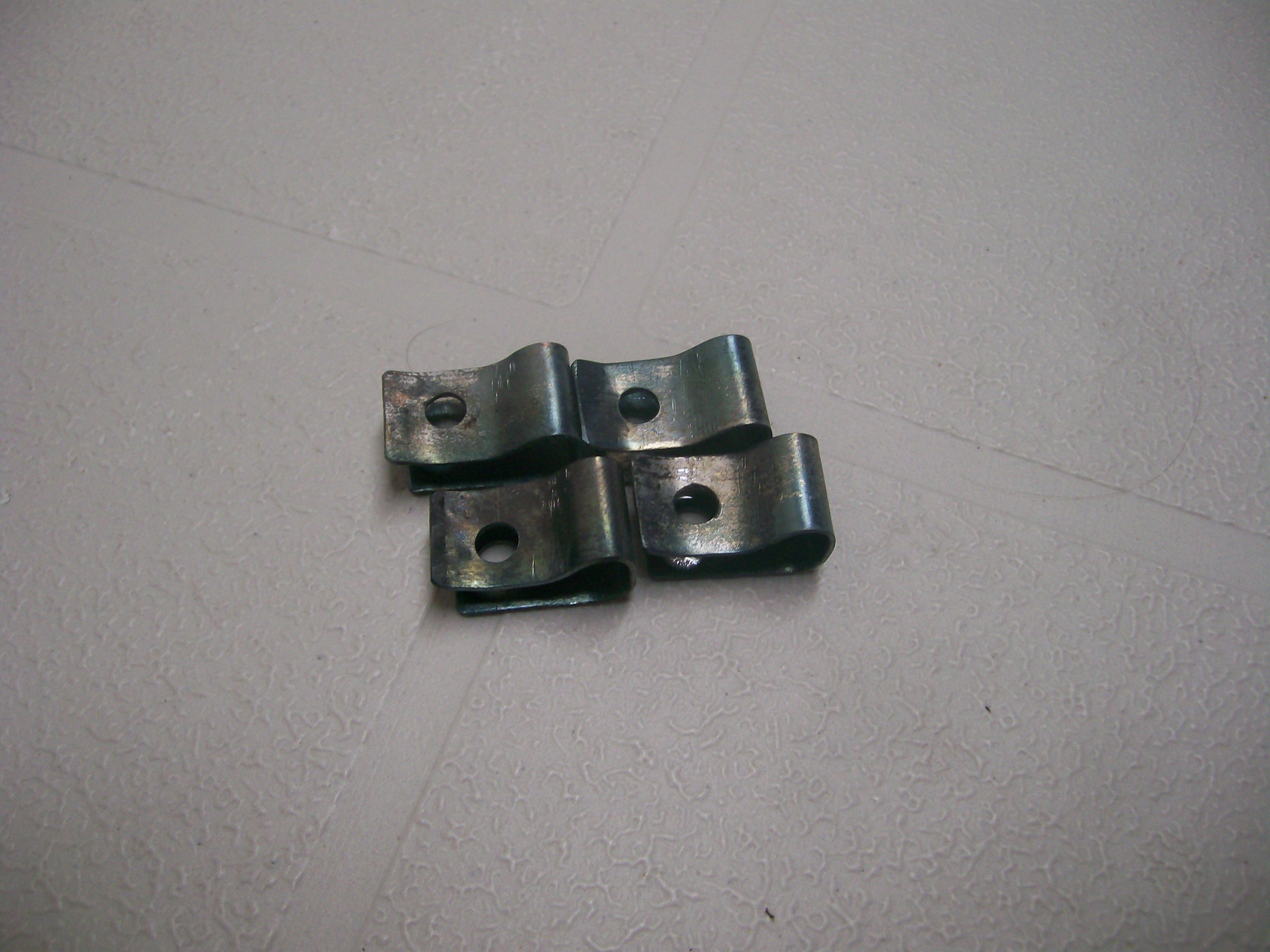
Thanks. I probably never would have gone down this path if you hadn't created this thread in the first place! I was thinking that the vent grills in my car would have the clips intact, but I'd never taken a close look until I read your write-up and became intrigued. When I finally got around to it, I discovered that the clips were missing altogether (the PO had done a lash-up job, which included two-sided tape to hold the chrome grills in place). And by the time all of this became known to me, you'd sold all of your clip sets and I had to look for other options. The main uncertainty was whether the clips really needed to be made from tempered steel to work properly. Based on my what I've learned, the answer seems to be, 'not really'. My torch-and-quench tempering scheme seems to have been adequate, helped by the fact that the forming process creates a bit of localized work-hardening around the bent areas. And then, the legs of the clips don't have to spread that much when the clip is being pushed into place. In answer to your question, it probably would take me 15 minutes to make a new clip. Side business? I'm guessing there's not more than another 50 customers left out there in Z-Land, so not enough in it to be worthwhile. Maybe someone else will be interested in taking it on, though.Buyer: 'Is that the real mileage on the car?' Seller: 'What would you like it to be?'Now that Hardway has sold off his inventory and doesn't look like he's planning to commission a second run, I feel I can share my D-I-Y strategy with those of you who still need these pieces. The clips aren't terribly difficult to fabricate from sheet stock and they don't have to be made from spring steel (that comes afterwards). Here's how I made mine: 1. Using tin snips, cut 4 metal strips from 0.022" sheet (or close to that). After cutting, flatten the strips on a hard surface with an autobody hammer. Then de-burr all the cut edges with a file. x After cutting, flatten the strips on a hard surface with an autobody hammer. Then de-burr all the cut edges with a file. This had yet to be done for the pieces in the photo. 2. Fabricate a forming buck from a small piece of hardwood (softwood won't do). You'll need the buck to form the 'bump' in the closed end. The 'bump' shape is mandatory -- it provides clearance for the stamped flange that runs around the periphery of the vent opening in the hatch outer sheet metal). I used a power sander and a Dremel sanding drum to make my buck. When you're happy with the shape, mark the side edge for the location of the centreline of the hole that you'll need to drill in the clip after you've bent it to shape. x 3. Mount your buck in a bench vise, along with one of the metal strips. The vise jaws should clamp on one end of the metal strip and the buck simultaneously (keeps the metal strip in position during the bending process). x 4. Now shape each strip using, as appropriate, either hand pressure or your autobody hammer (use the flat part of the hammer for the outside bends and the 'pick' end for the inside bend). x x 5. Mark and centre-punch the hole center before you remove the finished clip from from the buck. Then, using another strip of wood of appropriate thickness as a backing/spacer piece, slide the shaped clip over the wood and then clamp in some fashion to prepare for drilling the hole. Because the hole has to pass through both the upper and lower leg of the clip, you'll need both the spacer piece and a backing board. It's preferable, but not mandatory, to use a drill press here. De-burr both drilled holes afterwards... 6 6. To finish up, give the clips a bit of 'spring tempering' by heating them up with a torch (get them just to start of glowing red) and then dunking them in cold water (sorry, no photo for this step) 7. Here's my end result... The total project probably took me 3 or 4 hours to complete (making the buck is finicky). Materials costs were ~ zero. Best part: The clips worked perfectly during the installation of my vent pieces.


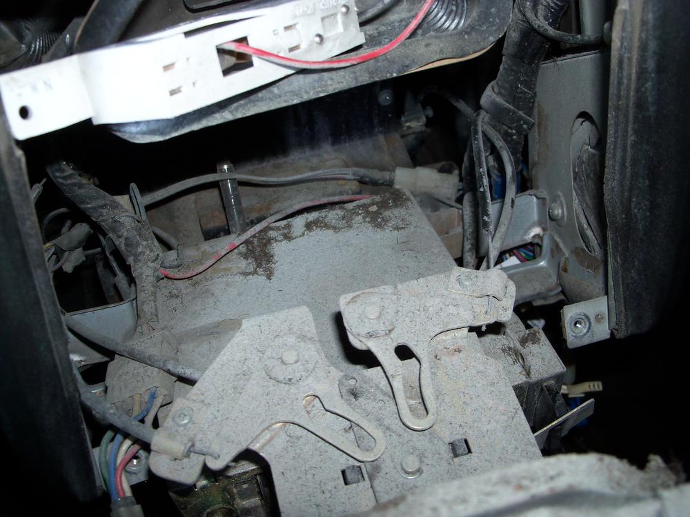
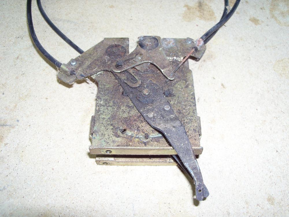
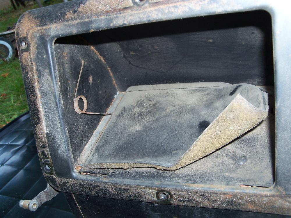
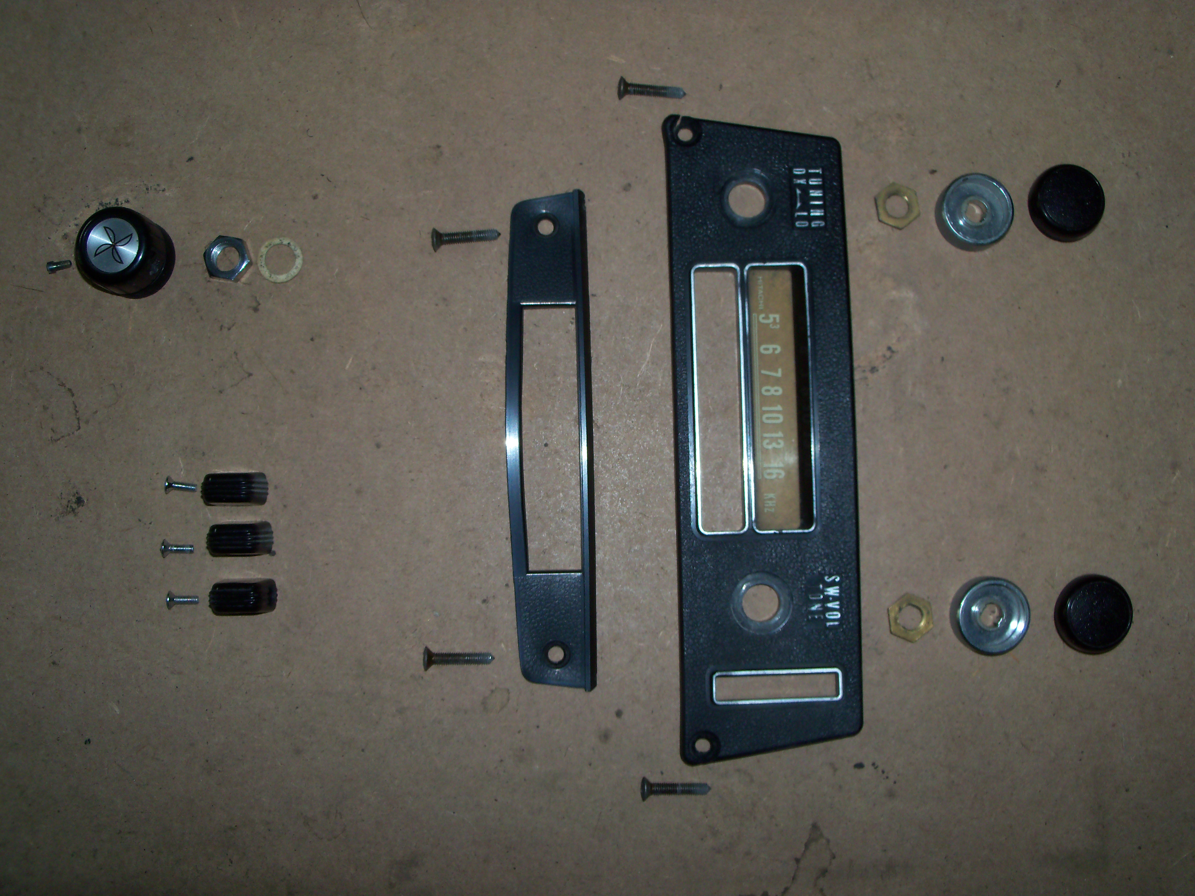
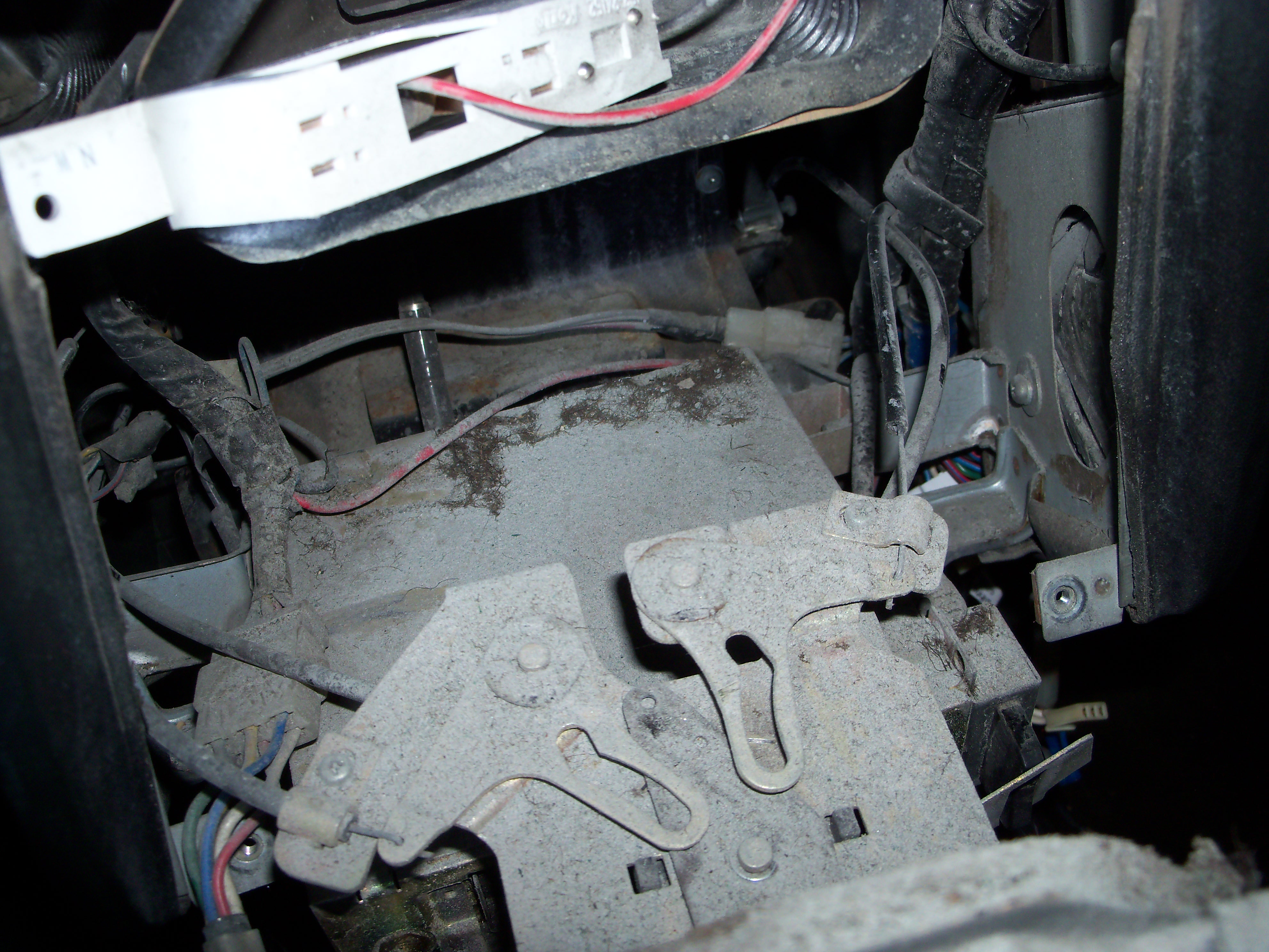
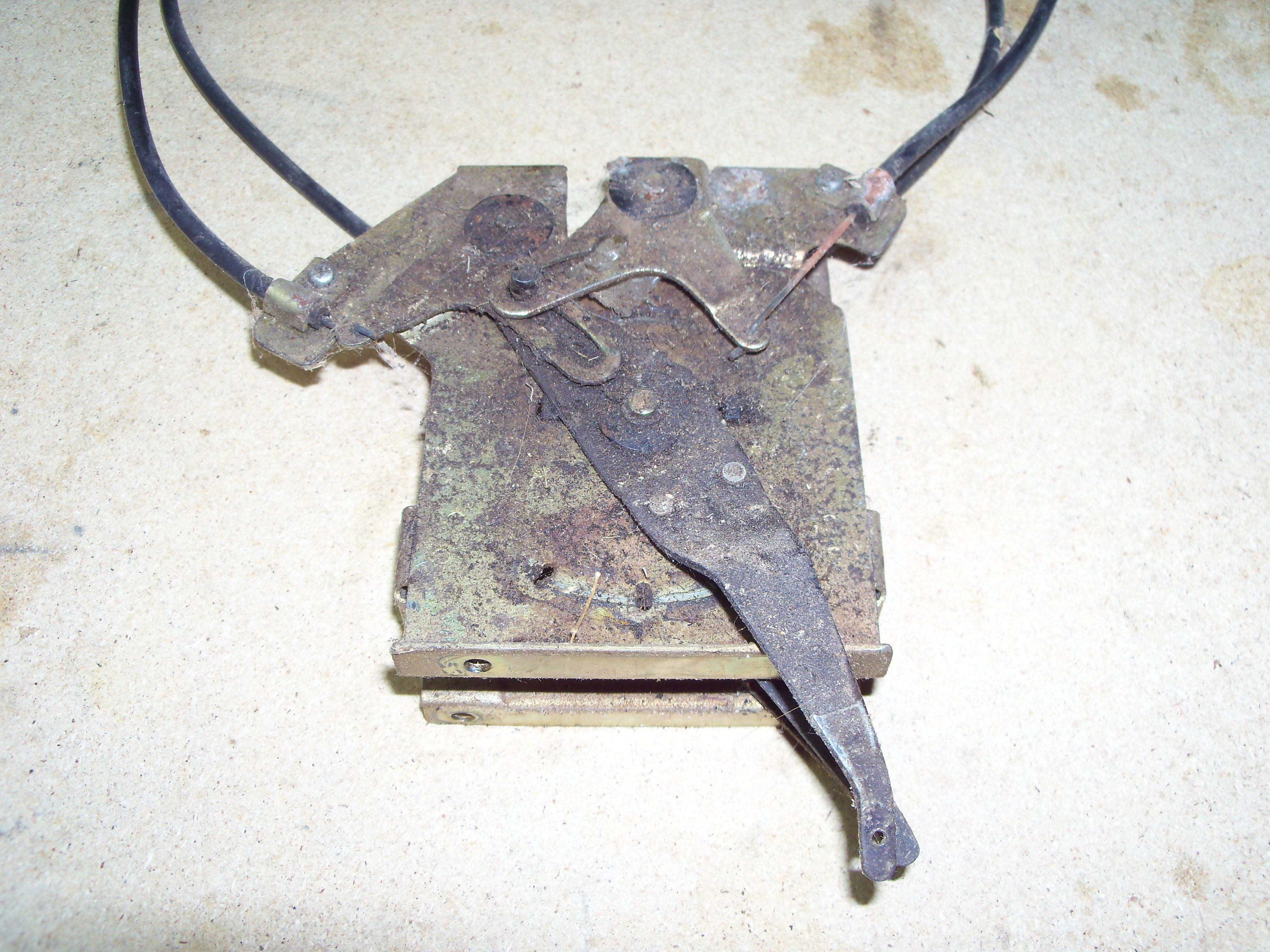
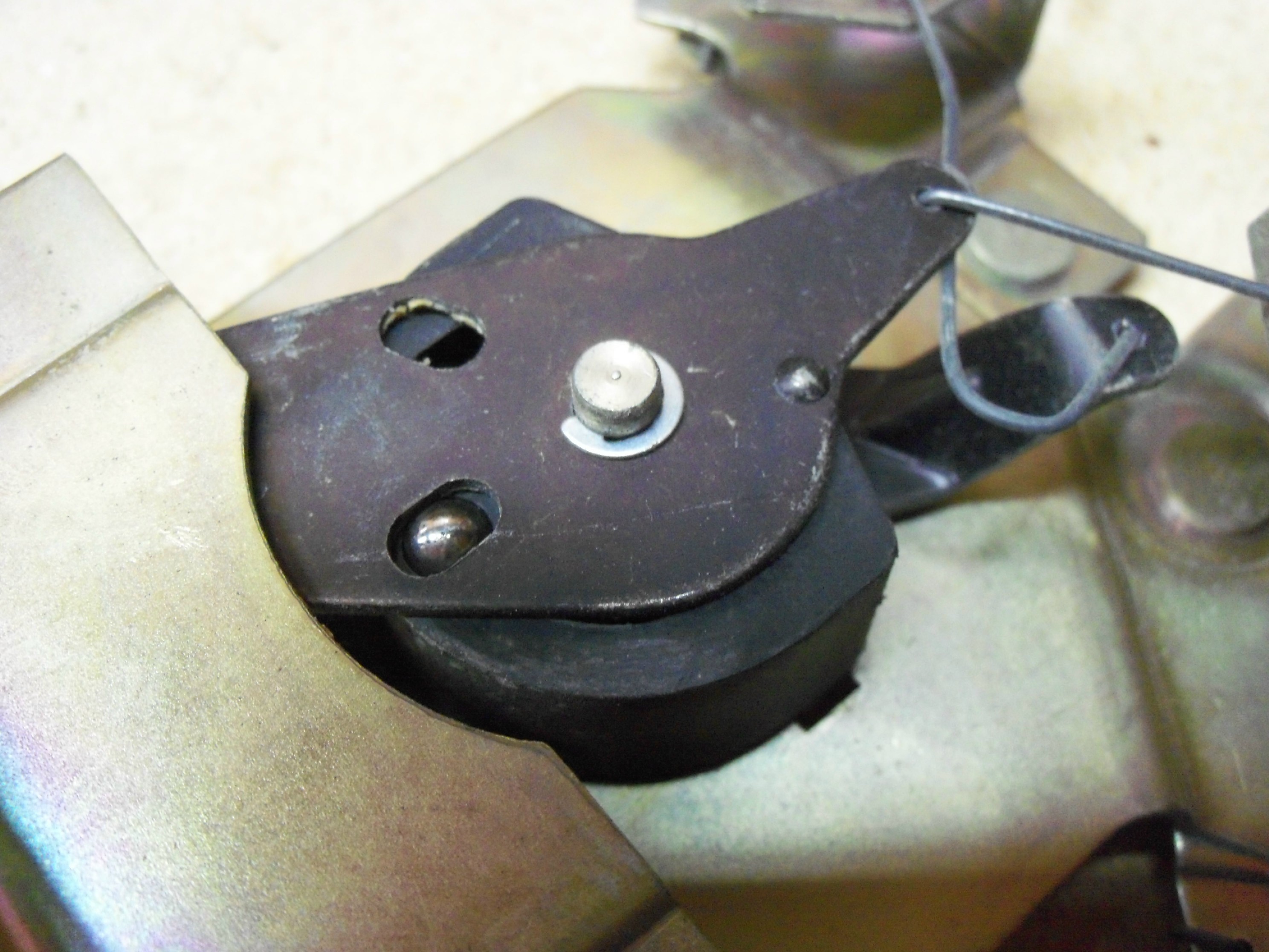
 As noted by others, you have a bit of a 'task' ahead of you in order to fix the stuck lever. The centre (tunnel) console has to come out first. Be careful not to break the plastic. You'll need to detach the choke lever assembly from the console. Remove the radio control knobs and fastener nuts, then remove the radio faceplate. Remove the knobs from the heat/vent control levers. Remove the Blower fan speed control knob and the retaining nut behind it. Remove the Map light faceplate and then lever the map light housing out of the heater fascia plate. If possible, pop the wiring connectors free and remove the map light altogether. At this point, you should have an assemblage of parts that looks like this (these are from a Series 1 car, so your parts may look a bit different)... x Now disconnect the four heat/vent control cables where they connect to the Heater assembly. You'll find three of the cable connections on the pssgr side of the Heater assy and the fourth on the left side. The securing clip for the cable that connects to the heater control valve (lower right side of the Heater assy) is often corroded. It will probably help to apply some penetrating oil first and let it soak in for a day before you try to loosen the screw. Remove the four screws that secure the Heater fascia plate to the Dash frame. At this point, the Heater fascia plate is ready to come out. As you pull it away from the Dash, it will come away complete with the Heat/Vent control lever assy and the four control cables. The cables are curved and somewhat stiff, so you'll need to tug a bit to pull them free. The radio and the Fan Blower speed control knob will get left behind. The lower part of the Heater fascia plate is like a ring and it can break at the corner(s) if you pull on the fascia plate unevenly or too enthusiastically. Here's what you'll be looking at (sort of)... x Experienced Z owners will see that my control lever assembly had experienced not just a bent cable (not visible in the photo above) also a mechanical failure of the topmost linkage (a guide pin had snapped out of the lever frame, allowing the top upper lever plates to separate. An intact lever assy looks like this (note how the slots in the two top link plates both fit over a common 'peg')... x Here's what a bent control cable looks like this. On my car, it was the bottom lever and cable (goes to the heat control valve) that had problems. The cable was bent into a full J-hook shape. In the photo, the lever asy has been turned upside down, so you're looking at the bottom... You won't be able to unbend a bent control cable. Easiest is to buy new ones (Z-Car Depot has them, maybe others do too). Or you can do what Zed Head and I did, which is to buy a roll of tempered-steel 'music' wire and form your own. Not easy, but not impossible either. The Series 1 system used 1.0mm wire. Later versions used 1.2mm wire. The ID/OD of the plastic cable sheathing is the same for both versions, so you can use 1.2mm cable inside the Series 1 or Series 2 sheathing. Make sure you find out why your control cable bent and fix that problem too. Otherwise, your new cable will probably bend just like the old one did. Unfortunately, the top control lever operates two inner air control flaps that are buried inside the Heater assy. It's not likely that they've jammed just because the pivot points got a bit rusty. Instead, it seems more probable that the one of the padded vinyl covers used on the internal control flaps has come unglued from the metal flap plate (common problem) and is preventing the flap from closing fully... To the driver (or passenger), this would have felt like the control lever wasn't moving all the way to the right or left in its slot, so they would have started tugging on it to try to get the lever to go to the full 'OFF' or (more likely) 'HEAT position'. If I'm right (and I hope for your sake that I'm not) you're going to have to drain the engine cooling system, disconnect the heater hoses, pull the Heater assy out of the car, and then pretty much fully disassemble it. Big job.
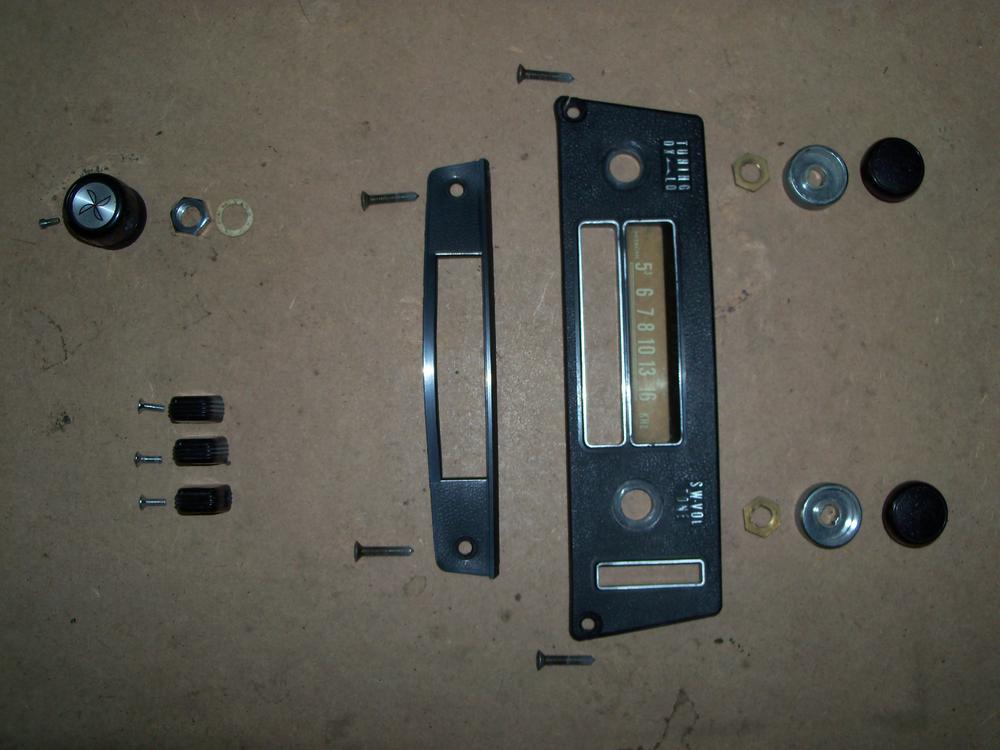

 Better than a cheap, 'Who dunnit' private detective novel.You might want to try to figure out why those wires got so charred before you cover things up. If they're in the vicinity of the driver-side headlamp connector, you've probably got issues with the three-wire connector on the headlamp pigtail. Or maybe a PO tried to install aftermarket fog or driving lights and made a mess of it (as in, short circuit). If the region of the harness that needs re-covering is relatively 'fat' (say, 1/4" diameter or more), the correct way to do the job will be by using loom tape ('wiring loom'). It's just like electrical tape but has no adhesive. Buy a roll that's about 3/4" width. It's inexpensive. Takes a bit of practice to learn how to apply it. There are a few on-line articles explaining the technique (try an MG or old Ford club website). Just don't use electrical tape.. It turns into a gooey mess after it's been exposed to engine compartment heat for a while. Nissan used thin, flexible black 'plastic' sheathing as the covering at the end of some of the skinny branches of the engine wiring harness. That sheathing turns rock hard with age and usually significant amounts have cracked and split away. Replacement sheathing is available in three or four different diameters from one of the specialty wiring connector suppliers (Vintage Connections or Eastern Beaver... can't remember which one). If you're not concerned about restoring the harness to OE specs, there are a variety of more modern wire sheathing solutions available.My column shell parts had similar problems (the styrene plastic that Nissan used for the housing pieces was not a good choice). Although none of the towers were completely broken off, a couple were splitting away near the bottom. I managed to glue the pieces back into place using krazee glue. The repair is probably a bit fragile, but it's adequate. My lower shell piece had a one-inch hairline crack that needed repairing. I used krazee glue in the crack and then backed up the repair by gluing a piece of thin plastic sheet (from food packaging) onto the inside of the shell to provide some reinforcement. I also did some sanding and 'coaxing' on the towers and the shell mating edges to try to get the shell halves to fit together flat and flush. I gave the shell pieces a couple of coats of SEM 'Landau Black' paint afterwards. I'm still not totally pleased with the way the two halves fit together, but they're a lot better than they were at the start.Why not shoot them an email and ask?Although they were stuck to the metal, I didn't really get the feeling that the paper gaskets in my horns had any kind of glue or sealant used. I agree with Grannyknot that you don't want water getting inside. I debated about using sealant. I even thought about using thin-sheet neoprene foam rather than paper when I cut new gaskets. However, I was worried that a thicker or softer material might mute the horn, so I just used thin gasket paper (dry). After all was said and done, I ended up with the characteristic Z horn sound that I wanted, but I don't think it's loud enough to get the job done in modern traffic so I'm going to back them up with a pair of FIAMM 'Freeway Blasters'.Agreed. I was thinking that he could extract a suitable contact point from some non-Z relay (pref. a from an older Nissan product) and then transplant it into the relay from his Z.I would go for a generic dustboot (no one will know... or care). Probably $4.99 each. Have a look on eBay.No car manufacturer adds parts that will never be seen (i.e. parts with no perceived value to a buyer) without a good reason. Nissan must have decided that their OE-design struts (which didn't use a cartridge-style shock absorber) were failing prematurely because of either water/salt-induced corrosion and/or dirt intrusion at the top of the strut. Of course, you will be installing cartridge-style aftermarket shocks made with modern materials and there's reason to expect that they're less susceptible to top seal failure than the somewhat old-fashioned design that Nissan used on the S30's.A used relay would be the easiest solution. Whether you can get one without buying an entire wiper motor/transmission is another matter. Used relay? Five bucks. Used Z motor? Either cheap or expensive, depending on who's selling. The big vendors say, 'NLA'. A Honda motor may be your best bet. $90. Still, it's just a relay. Go to the local pik-n-pull and buy a dozen. You should be able to find a piece to swap in. Nobody will ever know.Don't throw away the metal sleeves from your old grommets. The replacement pieces from 240ZRubberParts don't have them.


Important Information
By using this site, you agree to our Privacy Policy and Guidelines. We have placed cookies on your device to help make this website better. You can adjust your cookie settings, otherwise we'll assume you're okay to continue.