


Leaderboard
-
Jeff G 78
Free Member8Points3,007Posts -
.JPG.cfcada9cf1c1b502df3f5f2f2ca3ff36.JPG)
SteveJ
Free Member7Points9,646Posts -

Freez74
Free Member4Points232Posts -
HusseinHolland
Free Member4Points1,031Posts


Popular Content
Showing content with the highest reputation on 09/17/2023 in all areas
-
Looks like you got it! I've been happy with mine since I got it to fit right. It is much louder than stock exhaust.3 points
-
3 points
-
3 pointsI bought an assorted kit of stainless steel ball bearings that include 2.5, 3, and 3.5mm so I think one of those should work. I'll follow up once I get them and try them out3 points
-
My welding skills are not great. I am okay where there was no gap, but I keep blowing holes while trying to fill the void. About half the circumference was tight together , but there was a 1/16" gap in parts. I'm getting there, but lots more grinding than I should need. 😆2 points
-
One note from my experience, when I connected my HEI, I ended up having to totally bypass the resistor. I have a 1976, so my wiring was a bit different than yours. I ended up connecting the B (blue wire) and C (Black with White stripe) to the Negative and Positive Ignition Coil Terminals, respectively. Here is my thread for reference: Post #24 onwards is likely pertinent and may be helpful to you. I initially thought this was a fuel delivery issue, so I posted it in the wrong part of the forum before other more knowledgeable members here steered me in the right direction. I guess the good thing is that I did clear out my fuel vent lines, replaced my fuel filter, and developed a very good understanding of the fuel and ignition systems in my 280Z. Good luck, and I hope this helps!2 points
-
I know, right? I've survived three AZ summers already. This summer was brutal. We had 55 days over 110F and 31 consecutive days over 110F. Last summer, I think we had less than 10 days over 110F. I plan to get my Z ready to daily drive once the weather is cooler.2 points
-
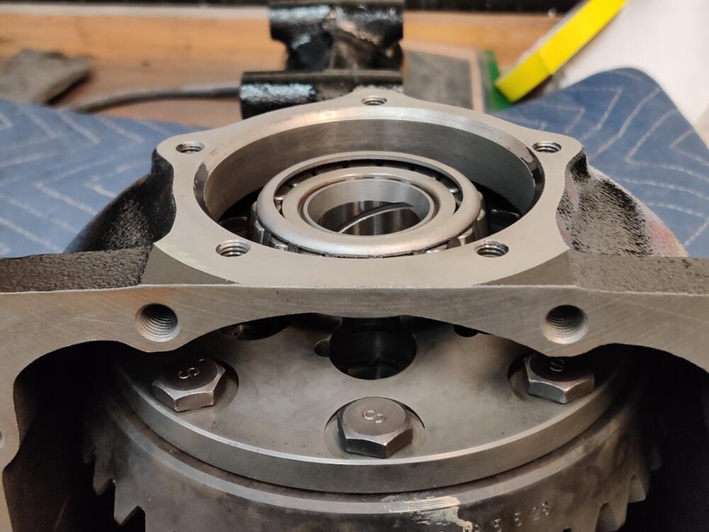
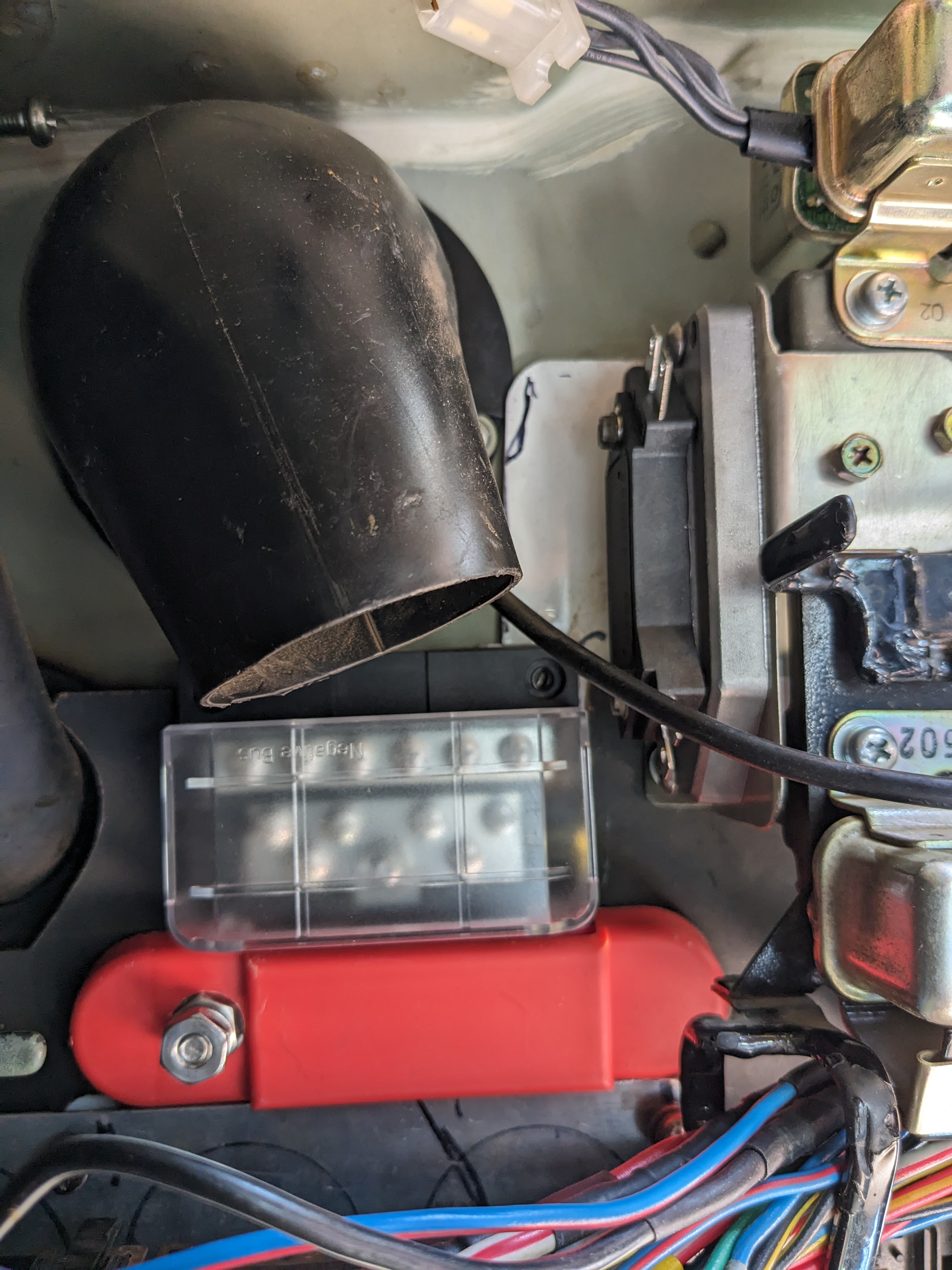
I have some gear marking compound coming also. I plan to check rotation torque and adjust if necessary by backing off the pinion nut a bit and retorquing. Then, I will assemble the carrier in place again with no shims on the left and all on the right. I'll check back lash for kicks (because I am sure it won't change). And then, I will put the gear marking compound on and see what's what. My guess is that the pinion height has changed, probably due to differences in the pinion bearings. I don't know how (at the moment) to figure out what to change with the pinion shims. I will research.2 points
-
Has it really been 2 1/2 years already!! Wow, I have no sense of time2 points
-
The W on the module is from GM's labeling. Might be that GM used a white wire. In your writing above I thought that you were referring to the GM HEI module not the Nissan module. Didn't realize you were deep in to the circuit board of the Nissan module, looking at those wires. Most people just use the diagram or the labels on the wire clamp. Don't know anything about the other person, but the basic test to see if the wires are connected correctly is to watch your timing light mark afterward. If it jumps around it's probably backward. If they're backward it won't hurt anything you just swap them. There's an accurate edge of the variable reluctor signal and a fuzzy edge. @Captain Obvious has some old comments about that.2 points
-
2 points
-
2 pointsSpeaking of POR15, I’m sure most folks here have bought a can no matter the size, Use it once and attempt to reseal it the best you can only to find out a while later that when you finally get the can open that expensive POR 15 is dried up!! Went to a fellow members shop in Al. No it was not @siteunseen!! Kenny showed me a trick that was passed on to him. When you buy a new can Don’t open it. Take a punch one hole on each side of the lid. Take two lag screws and put ‘em in. When you’re ready to pour remove both screws. Pour out what you need in a disposable cup, reinstall the screws flip it upside down to seal the screws and you’re ready for next time. He’s had this can for over a year and used it multiple times. Maybe it’s an old trick but a first for me. Hope that helps someone out there.2 points
-
2 points2 points2 points2 pointsGood stuff! I haven't had a horn since 2017. I've been yelling like a crazy person out the window in lieu of a working horn.
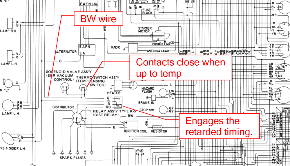
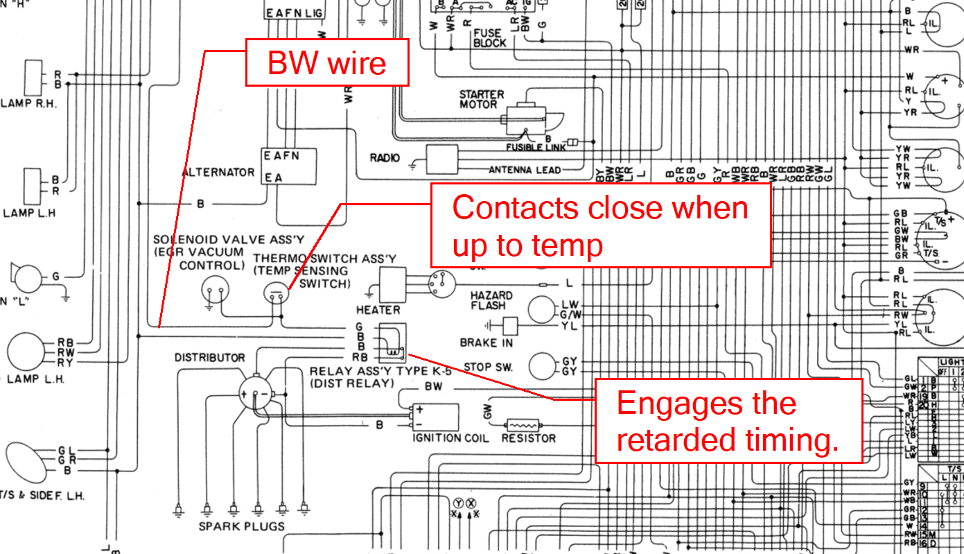
 2 pointsI agree. Use one set of points. The plus side is you won't have to carry a spare set in the glove box.1 pointMy plan is to add a resonator and a stainless steel braided flex pipe. The flex pipe takes some stress off the exhaust manifold studs. The system is okay for now. I need to get a flanged 2-1/2" adapter so I can mate the exhaust to my 6 into 1 header. The old adapter I had was a 2". I did have to give the front pipe some heat and beat to clear the trans mount. The header points right at it, so without a few more bends, it wouldn't have fit.1 pointI'm not going to verify my sanity nor anyone else's. This may help explain the erratic behavior. From the EE section of the FSM: (Note what it says about the dual points.) So when the engine comes up to temperature, the timing is retarded for the automatic transmissions. Here's how it looks in the wiring diagram: As @Yarb said, use one set of points. Tune to that. Be happy.
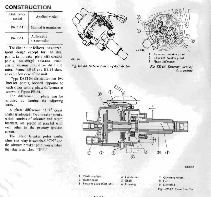
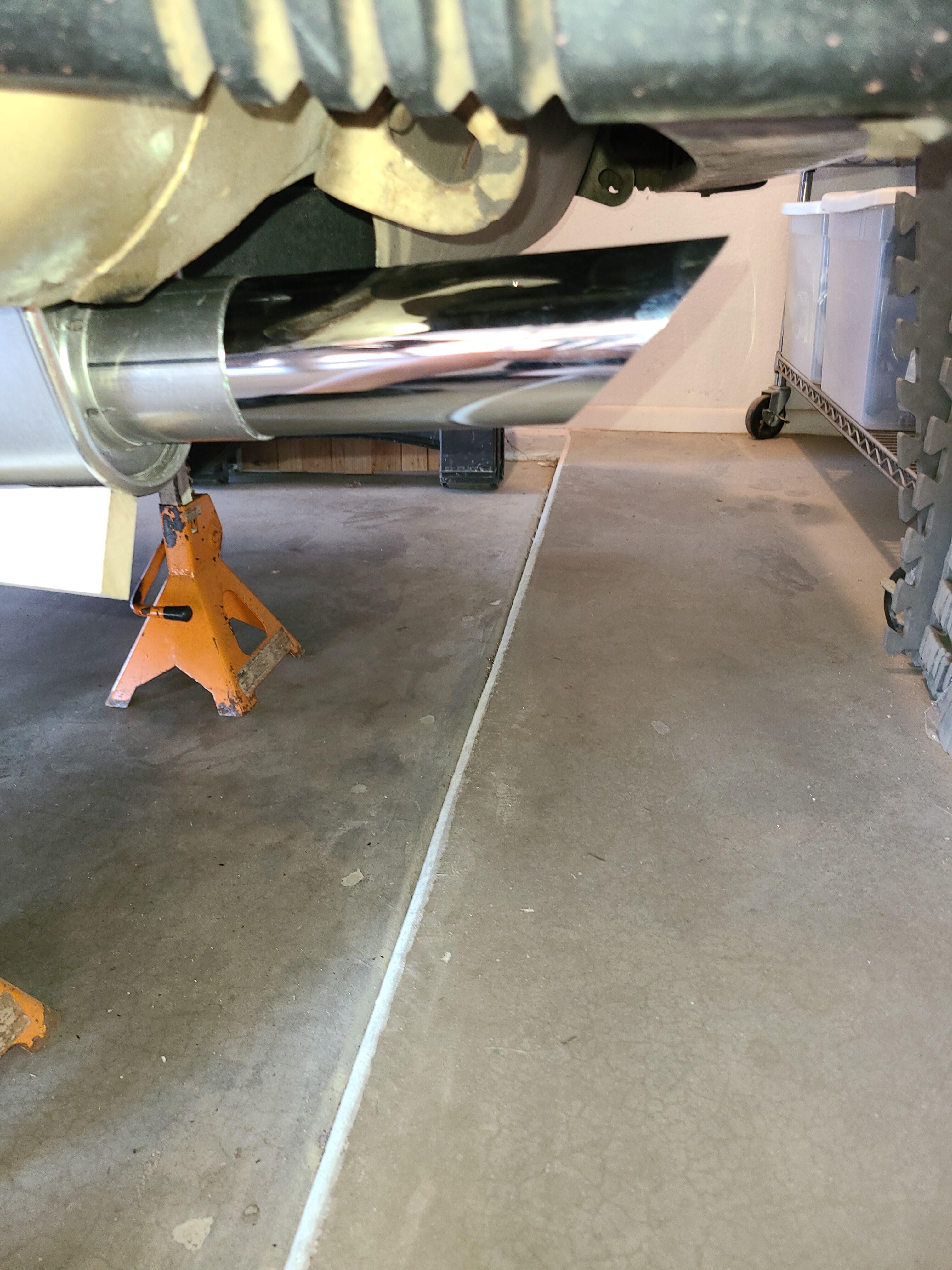
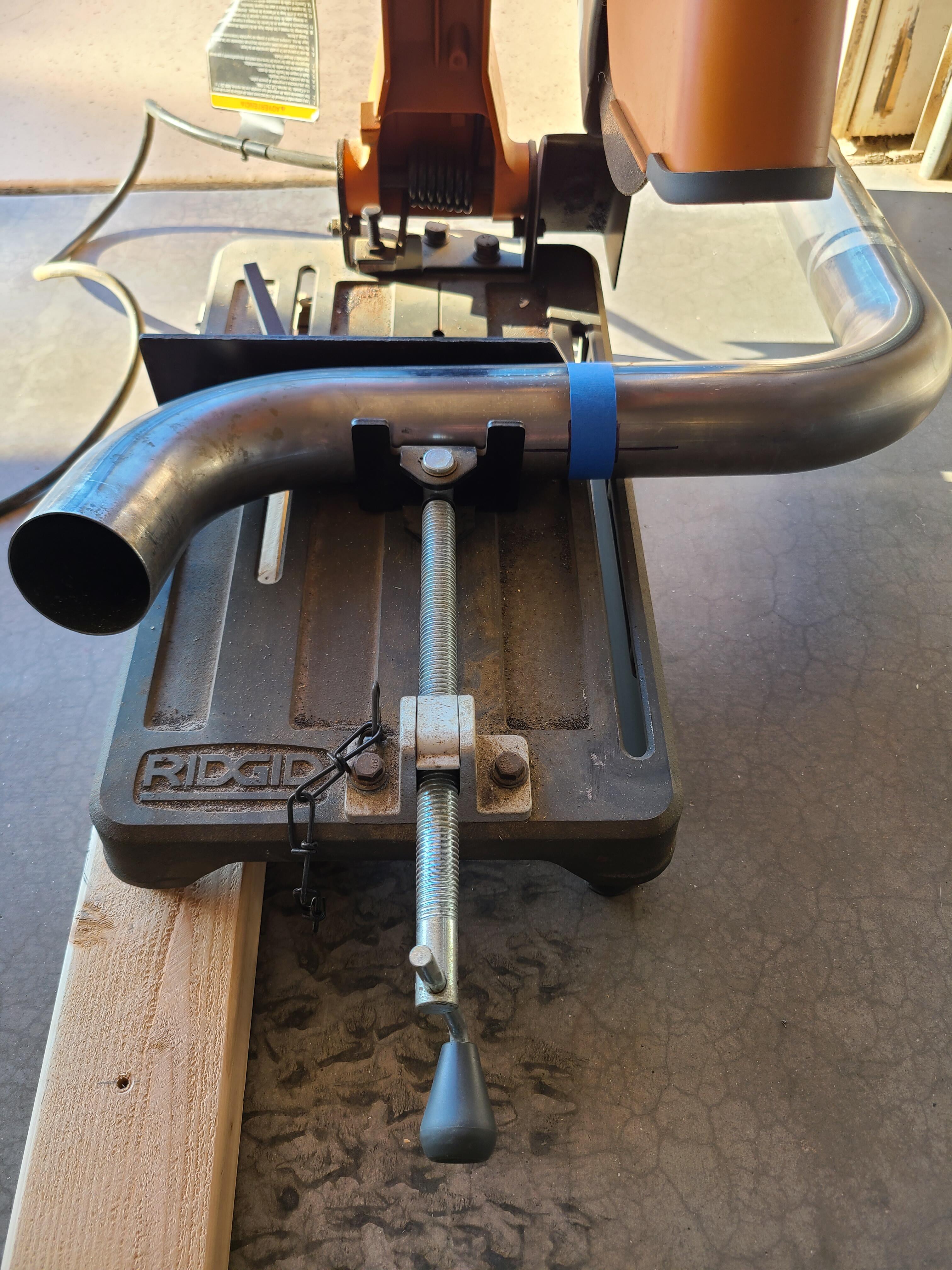
 1 pointI’m not an expert nor have I attempted this before. My initial thought would be just to connect one wire and try that first. I’m sure you’ll find an answer here from someone that’s been down that road.1 pointMuch better with 1" cut out. Still not a great fit, but it doesnt hit the body. 1-1/2" might have been better, but I'll live with it. This MSA chrome tip is a POS compared to the rolled version. I will find something better.

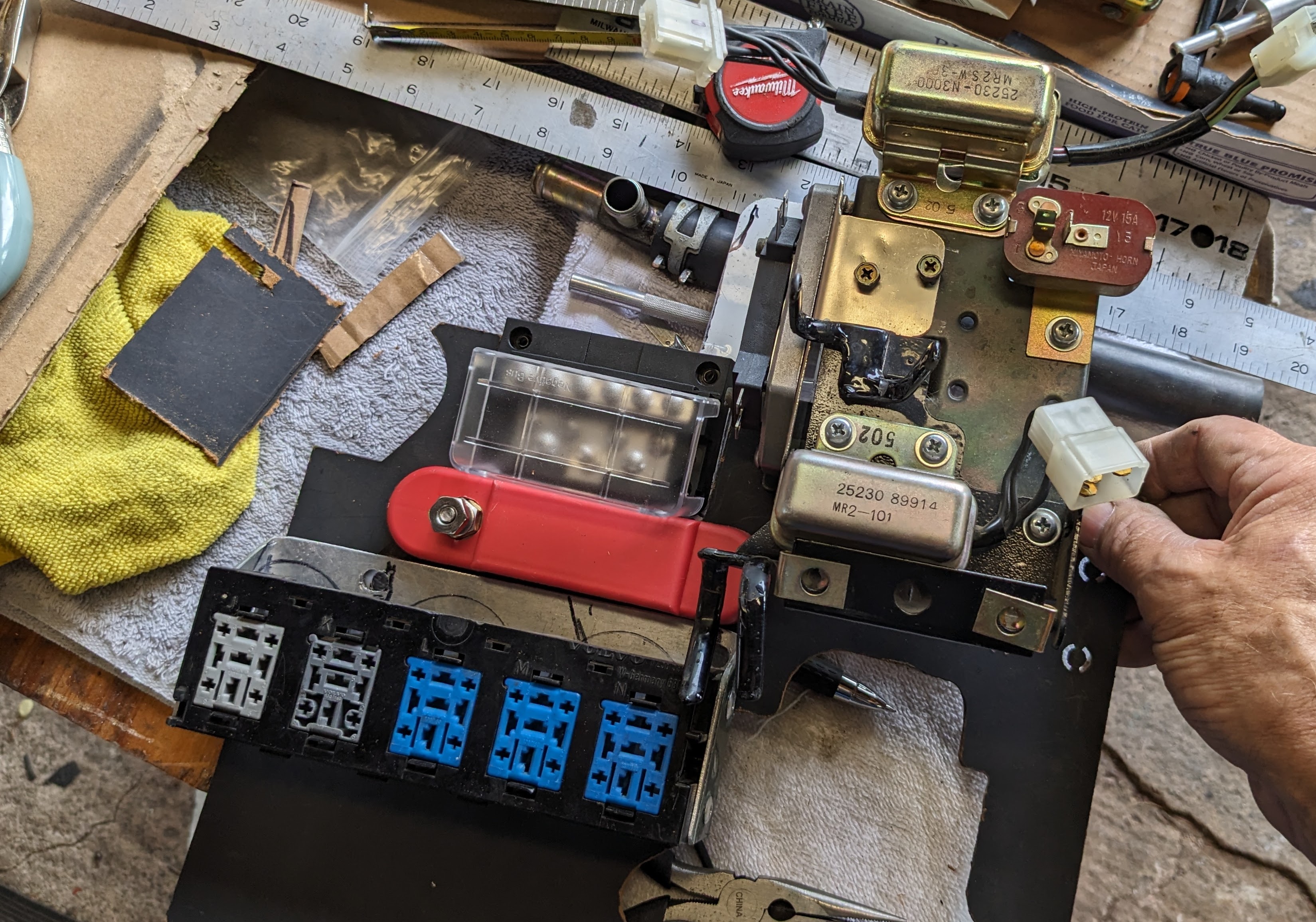
 1 pointHere's some info on that topic: https://www.classiczcars.com/forums/topic/67864-ignition-systems-analysls/ It's a little academic (and unfinished), but I find it interesting. Might just be me. In any event, I'm hoping the module issues here with @HusseinHolland resolve themselves easily. We can get into some of the deeper details if they don't.1 point1 pointI installed one of those systems last year, and it fit poorly. Had to heat and bend the mid pipe to get it to clear the floor, and the rear pipe was too long. I cut a one inch section out of it in the straight part, and put it back together with a 2.5 inch band clamp.1 pointThanks for the confirmation, EuroDat. I thought about moving it the bay, much less wiring to worry about. Playing with placing the HEI & heat sink, I couldn't find a nice flat spot to locate it, except under the triangle steel web in the left corner near the AFM. Even though I don't plan on driving the car in the wet, the fact that the connections at the HEI are unsealed is enough for me to stick with placing it in the cabin 😁
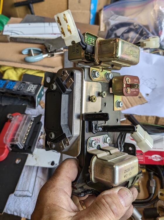 1 pointThanks for your experience, Paul. I had noted in EuroDat's directions that he bypassed the ballast. Since I'm using a Volvo 12v coil that didn't use the ballast to begin with, I am going to do as he did & bridge the ballast terminals, to keep the connections tidy.1 pointHi, I accidently swithed the wires when I quickly connected the TIU for a photo. I noticed it a year or two later, but funny no one else has made a note of it until now. The wiring for the HEI is correct. Trust me, when I was first testing it would not rev over 2500rpm. That was because I connected the two red - green wires on the TIU backwards Working from left to right, looking at the TIU with the wires coming out from under the TIU. B - Black wire: HEI Ground. Very important. BW - Black/White wire: HEI B (battery) BW - Black/White wire: Not used. L - Blue wire: HEI C (Coil trigger "-") R - Red wire: HEI W (reluctor input) G - Green wire: HEI G (reluctor input) You can set up the HEI next to the coil if you want. Just disconnect all the wires from the TIU. You can then use the power to the coil to HEI B and the HEI C terminal can connect to the coil negative. The blue wire on the coil negative will still need to be connected for the tacho to function. Make sure you ground the HEI well. PS: Agree with you on the terminal layout in the electrical schema. I try to find a terminal that is not full. Say it has 7 wires in a 8 pin plug, then I can figure out which direction I need to look at it.
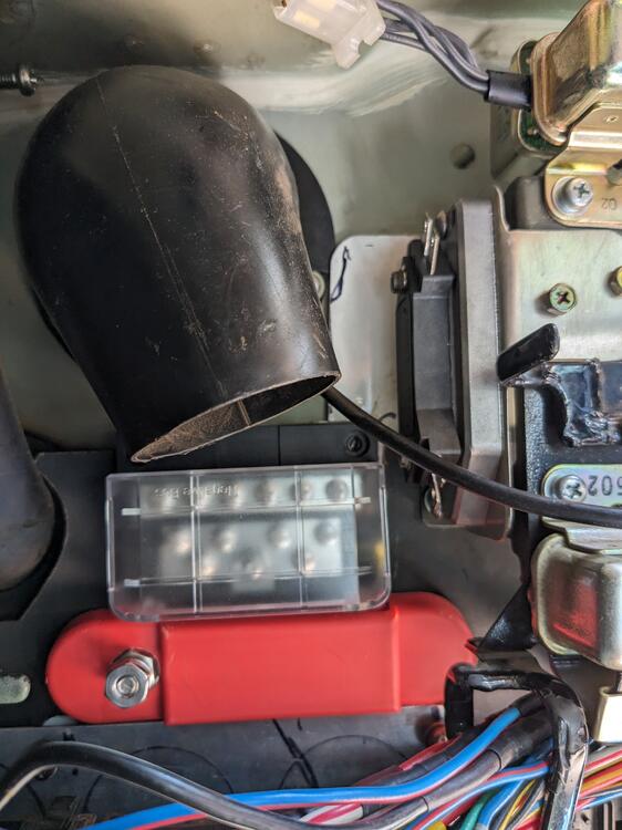
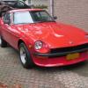
 1 pointI mounted the HEI module/heat sink to a bracket I made, that attaches to the side of the stock relay bracket, where the interval relay previously lived. Made it so the assembly is unscrewed from the face, as the bracket screws are otherwise inaccessible. I'll make a sub-harness so that the module can be removed with that attached

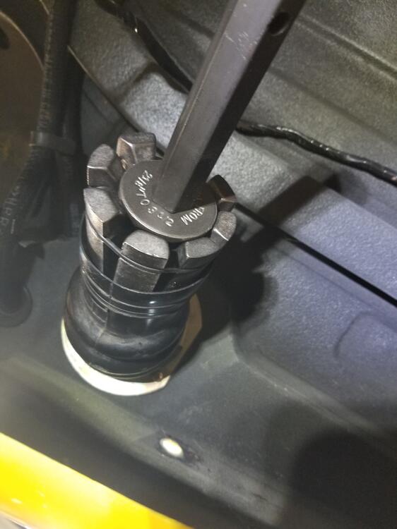
 1 pointThanks, I found some relevant posts. One of the frequenters of that site said, "It's been my experience that the backlash doesn't change notably. It changed .0005" on my own diff, and I've never come across any posts from someone whose backlash needed to be readjusted after installing the LSD." Before disassembling to remove the paint from under the side retainers, I measured the back lash, and it was about .014". The factory spec is roughly .004" - .008" (the factory service manual is not near me right now). I then removed the side retainers and scraped off the paint with a razor blade, and reassembled. After doing so, I put the side retainers back on, snugged the 5 retaining bolts, and measured back lash at .020". That was surprising to me, but I figured maybe I didn't measure it properly the first time. The factory workshop manual says that if there is too much back lash, to move shims from the left retainer to the right retainer. As assembled from the factory, the left retainer has one shim that I measured at .011" thick. The right retainer has two shims, one is .016" and one is .020". So, I took the side retainers off again and moved the shim from the left, and stacked all three on the right. I reassembled and measured back lash at .012-.013". Darn it. I found several pages back in this build thread, where I measured backlash before disassembling this diff, and it was .005". So, referencing the info from the Hybrid Z post, I appear to be in an unusual situation where swapping out the open carrier for an LSD has perhaps changed things substantially. Of course, in this instance I changed pinion bearings, so perhaps the pinion height has been altered now. As a next step, I will measure the turning resistance on the pinion shaft to rule out that I over torqued the pinion nut and have too much pinion bearing preload. I ordered a torque wrench which should allow me to check that properly - it will be here Monday. However, I don't have much hope that the amount of preload on the pinion bearings is my problem. Doing something other than using the shims that came with the differential is a departure into the wilderness - this is not something I have ever done before. So, I really am feeling lost about how to get this diff set up properly at this point.
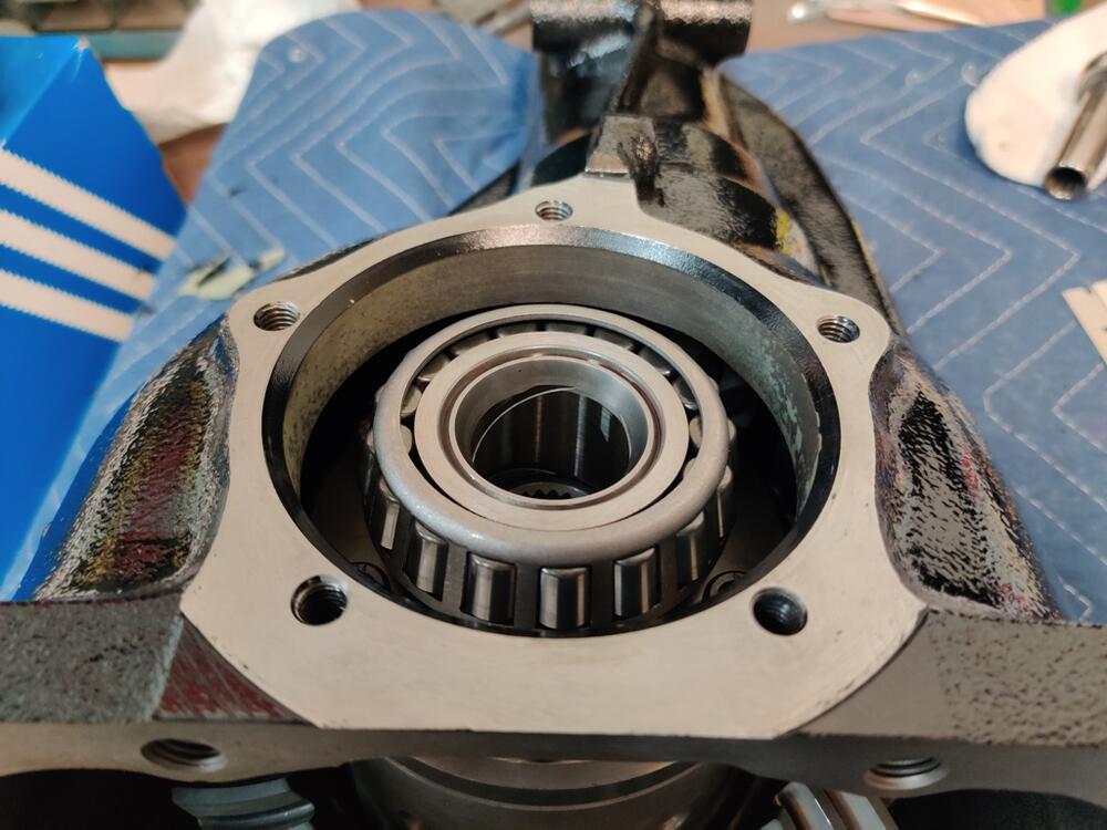
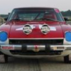
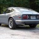
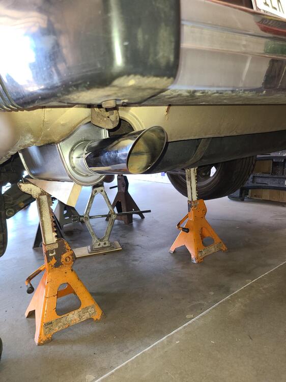
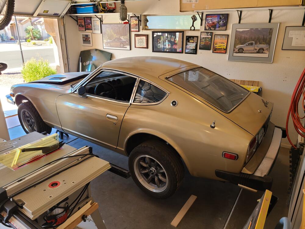
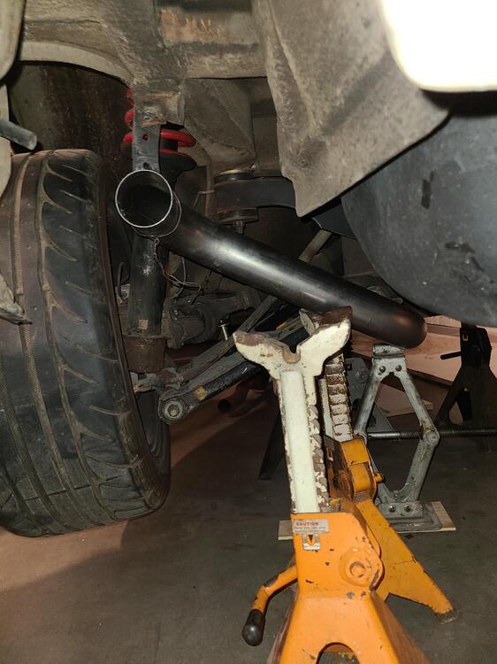
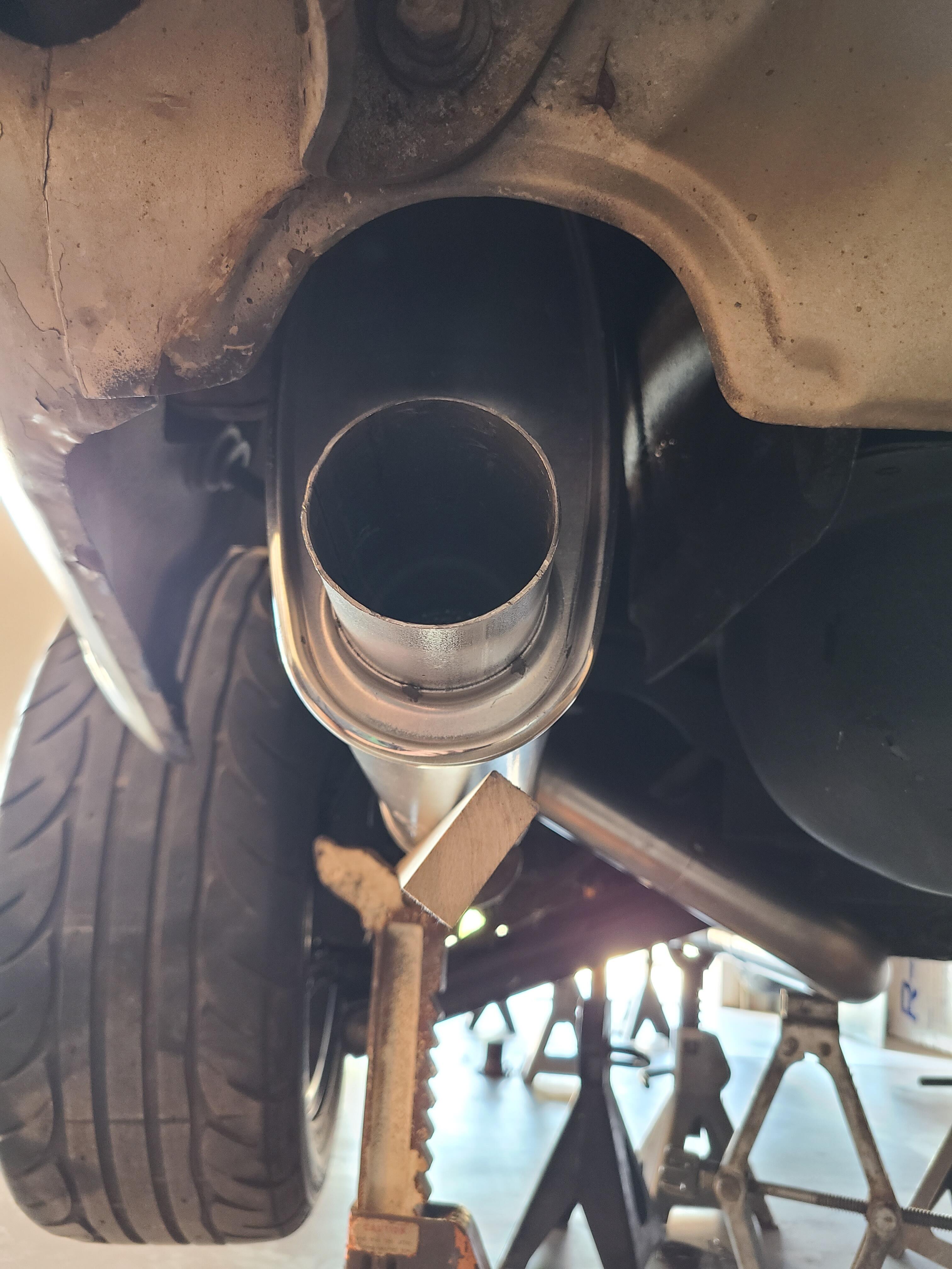
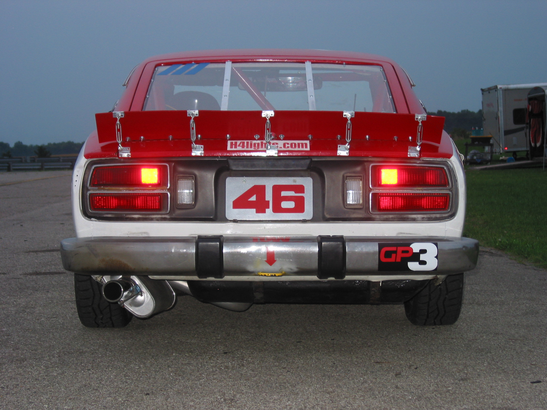
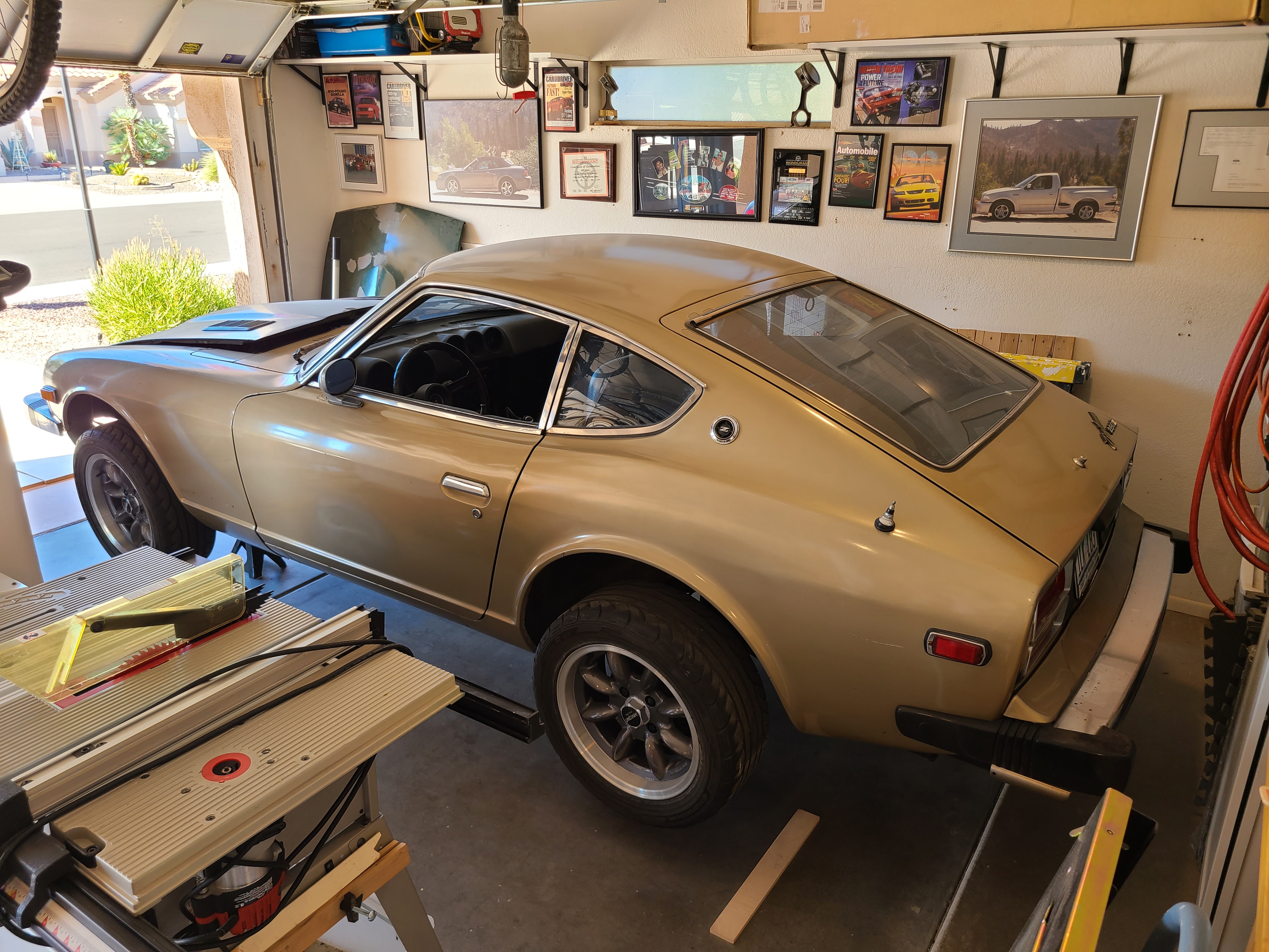
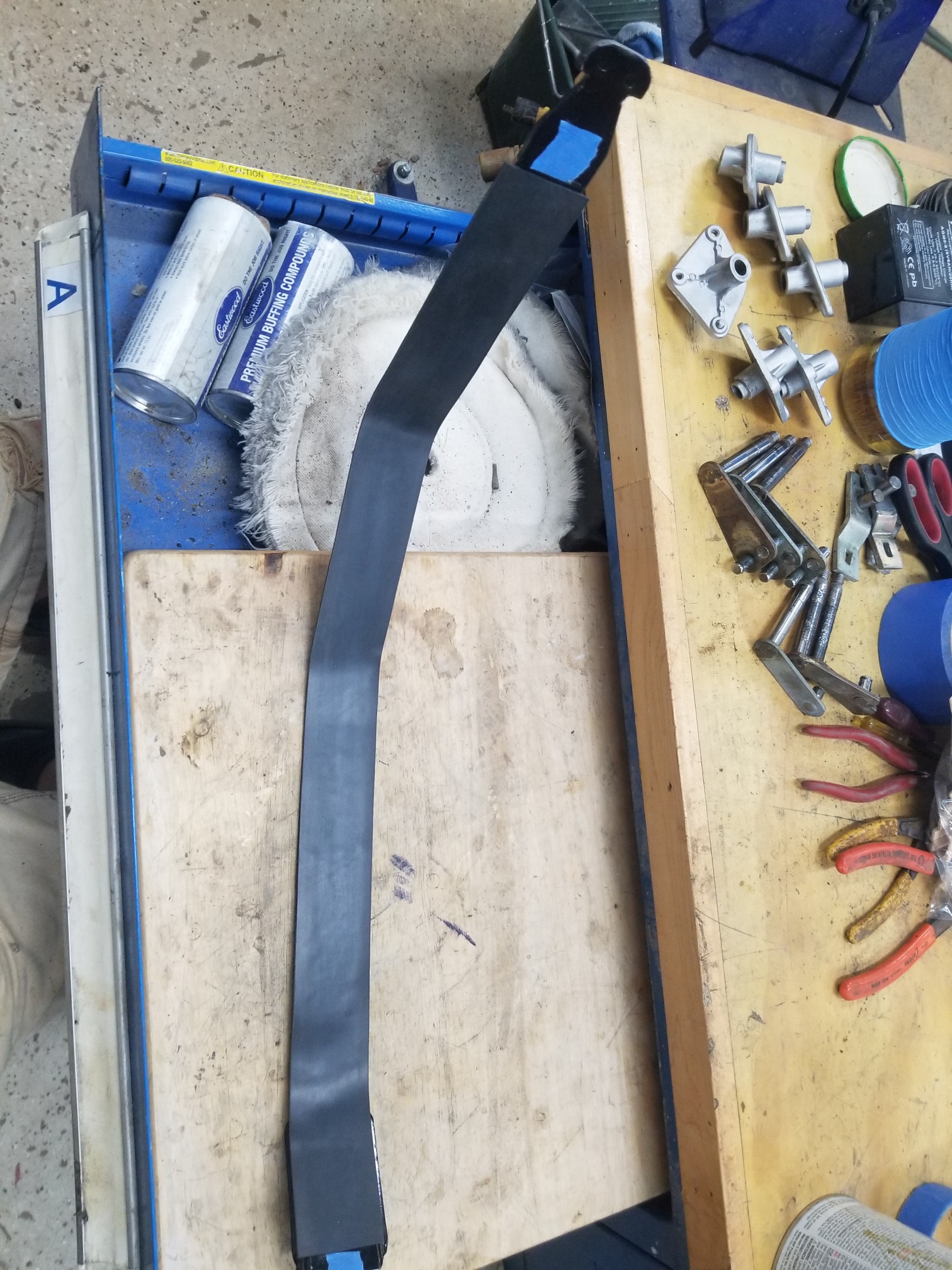
 1 pointThe extreme summer heat in Phoenix is starting to ease, so I finally started working on my Z again. It had been parked for 10 years before I moved from Michigan to Phoenix. I got it running enough to get it on and off the car carrier when I moved 2-1/2 years ago. After driving it less than 20 miles in AZ right after the move, I parked it again while I renovated my house. After sitting so long, it has developed lots of leaks, so I will have to pull the trans and replace the rear main seal, the trans output shaft seal, and the speedometer cable seals. I also have a MSA exhaust that has been in a box awaiting install for about six years. My header is an Arizona Z Car 6 into 1, so the MSA exhaust won't simply bolt up. I got the car up on jack stands, pulled the old exhaust, and started fitting the MSA exhaust. This is the second MSA exhaust I've purchased and they both fit like crap. The first was on my race car, so I wasn't too worried about it looking good or grounding out to the body from time to time. The muffler always hung down very low on the race car and I don't want my street car to look like that. On my 280Z street car, I just can't get it to fit right. I tried turning the muffler end for end and it just made it worse on the 280Z. I did turn the muffler around on the race car with the offset at the inlet and the center as the outlet. On both cars, the muffler was outboard too far. I trimmed the corner off the R200 diff like I did on the race car, so it doesn't look like it will touch anything, but the muffler is too far outboard no matter what I do with all the joints. When it fits best under the car, the exhaust tip is nowhere close to centered in the opening. It's close to 1-1/2" outboard from where it should sit. I think I will have to cut the rear pipe, shorten it between the two 90° bends, and re-weld it. I might just use this system for now and make a system from scratch that fits better and includes a resonator and a flex pipe. Has anybody gotten this sytem to fit on a 280Z without modification? I didn't get a photo with the muffler on the pipe, but you can see how far outboard the pipe outlet is compared to the space between the tire and the fuel tank heat shield. The exhaust tip is pretty much where it is on the 260Z race car, though the muffler is much higher with the muffler turned the proper direction on the 280Z.
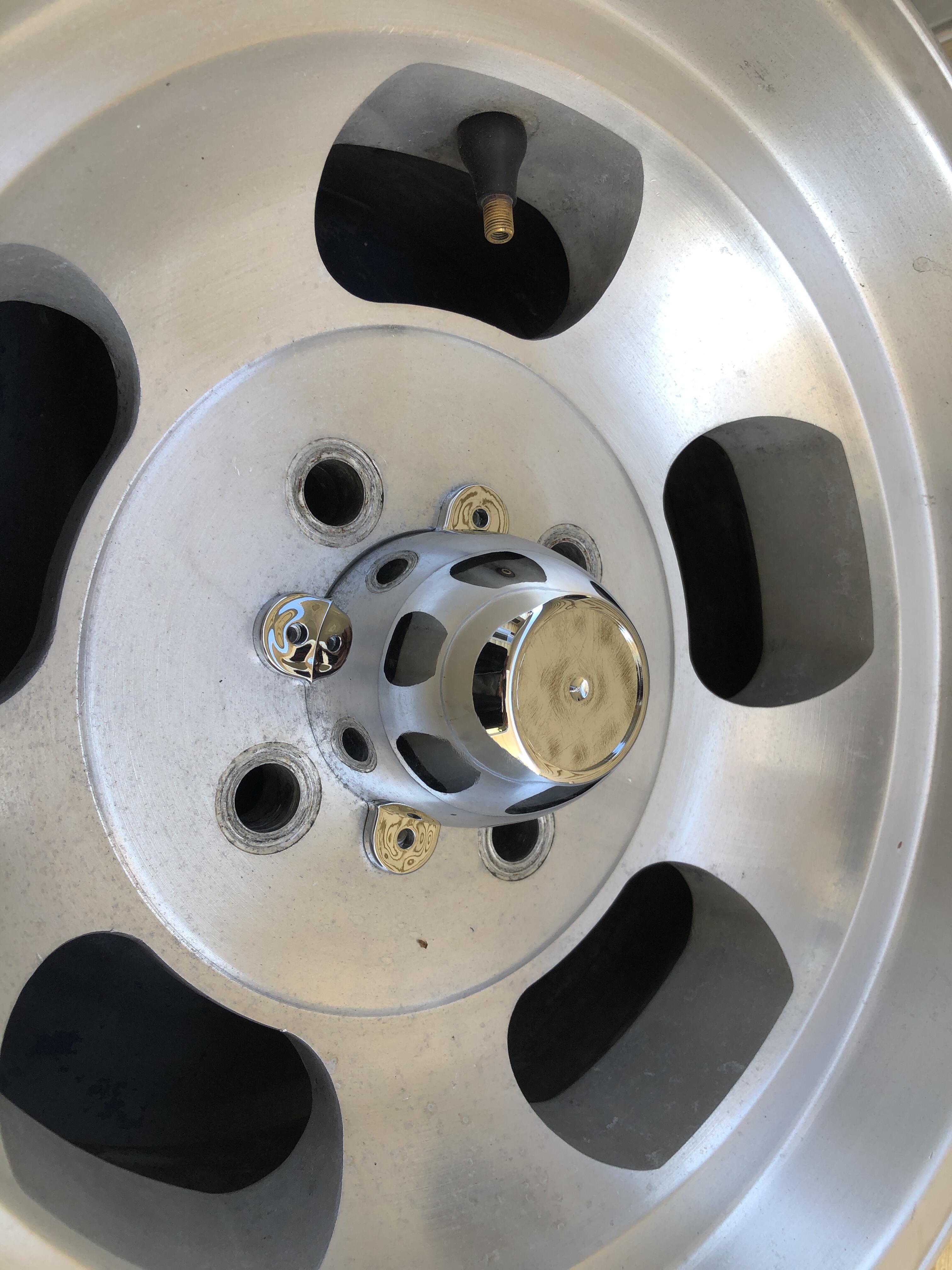
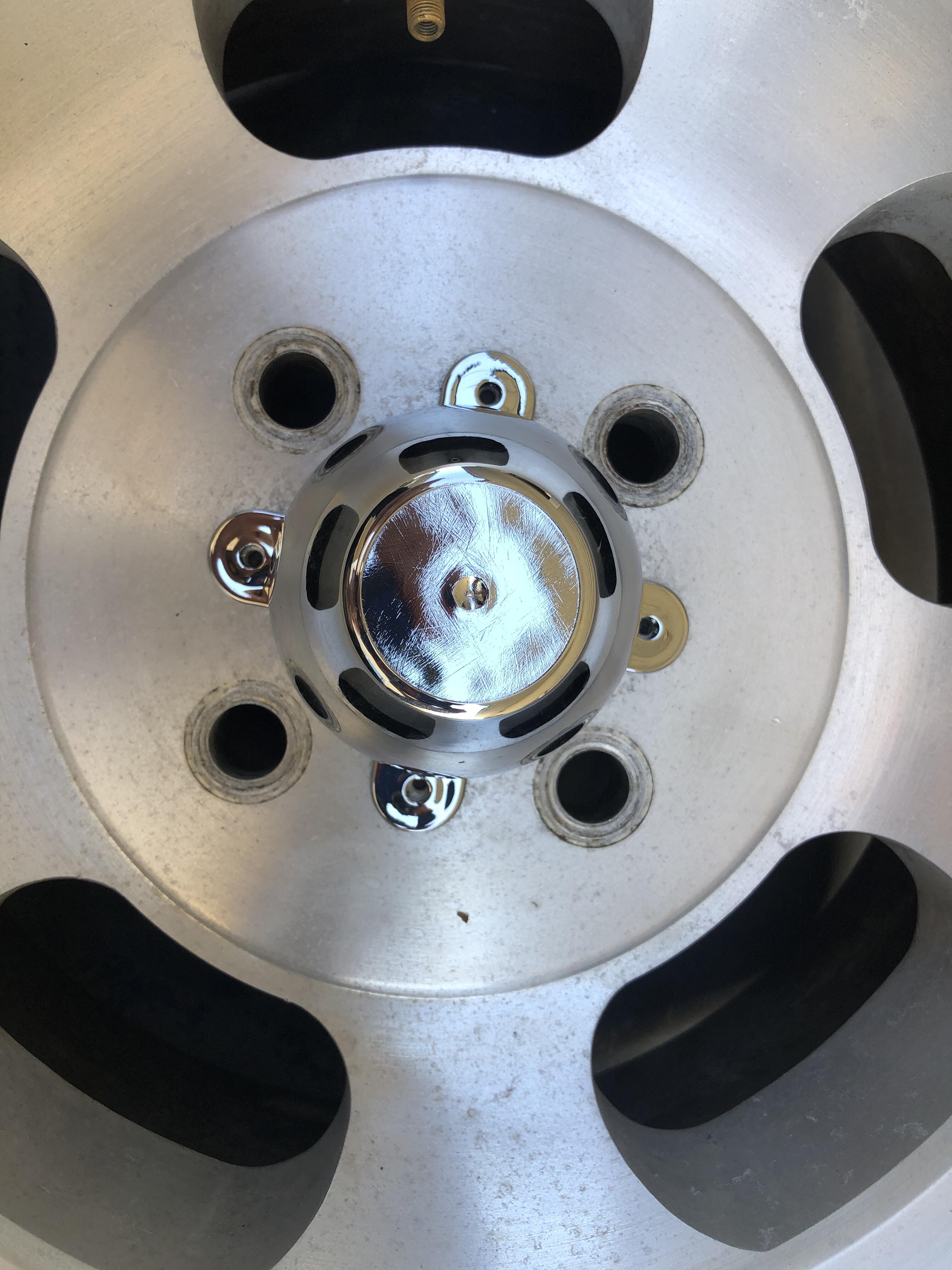
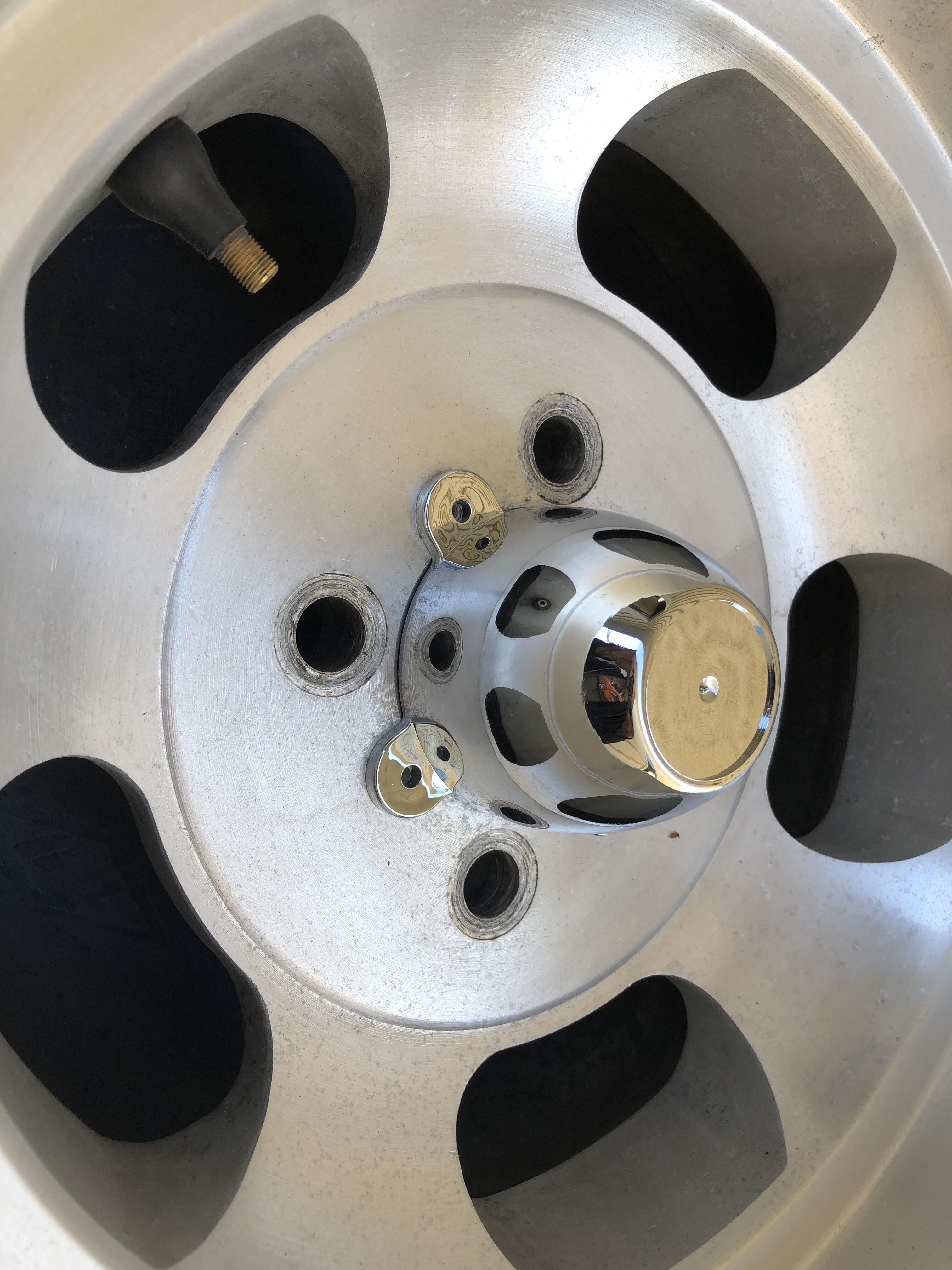
 1 point1 pointI’m good. I had ordered a harness boot from zcardepot that was labeled 1970-73, but I should have meassured the hole first. JDM Car Parts and MSA have the 280 boot, so I have one in the mail. Once I get that I can put this thing in, then on to fitting the body harness.1 point1 pointTo finish up this topic, the caps suggested above have arrived, and they are a perfect fit. The chrome is perfect, they even come with the four little screws! Now to transplant the old stickers. Or get new ones. Now the decision has to be made about how to protect the amazing bare metal finish on these wheels. Polish, clear powder coat, clear acrylic paint?
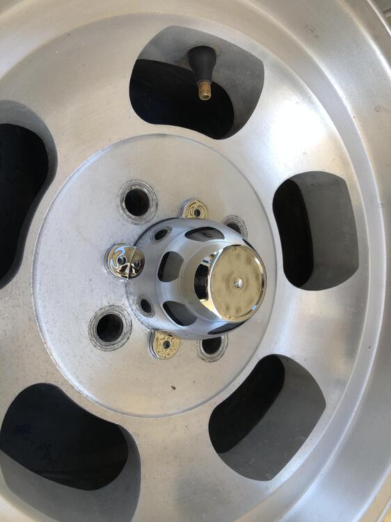

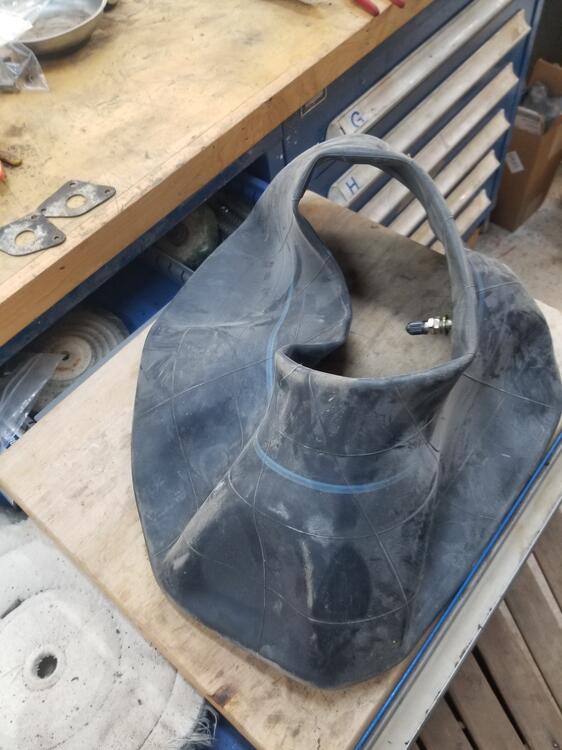
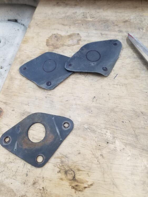
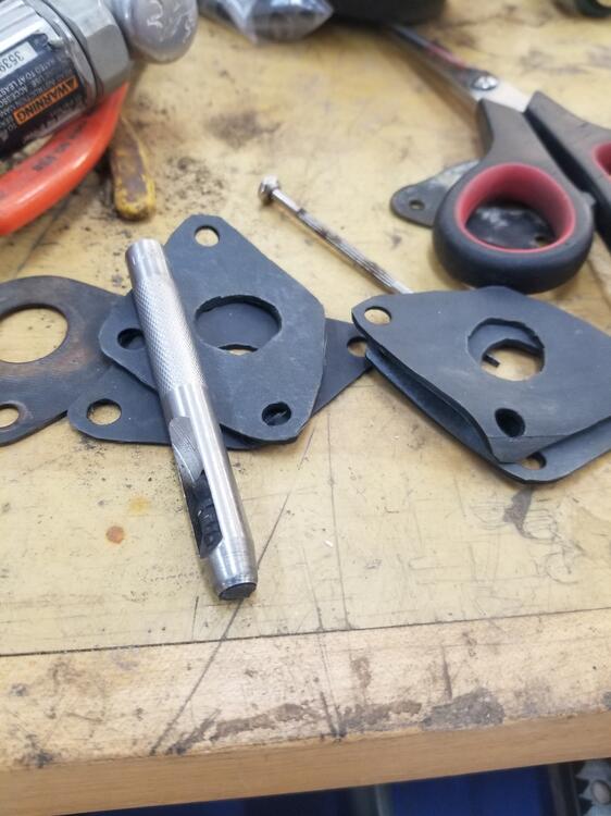
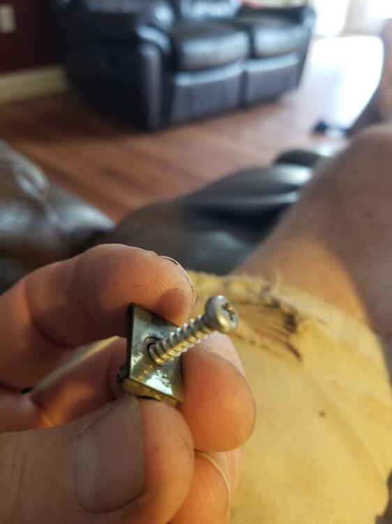
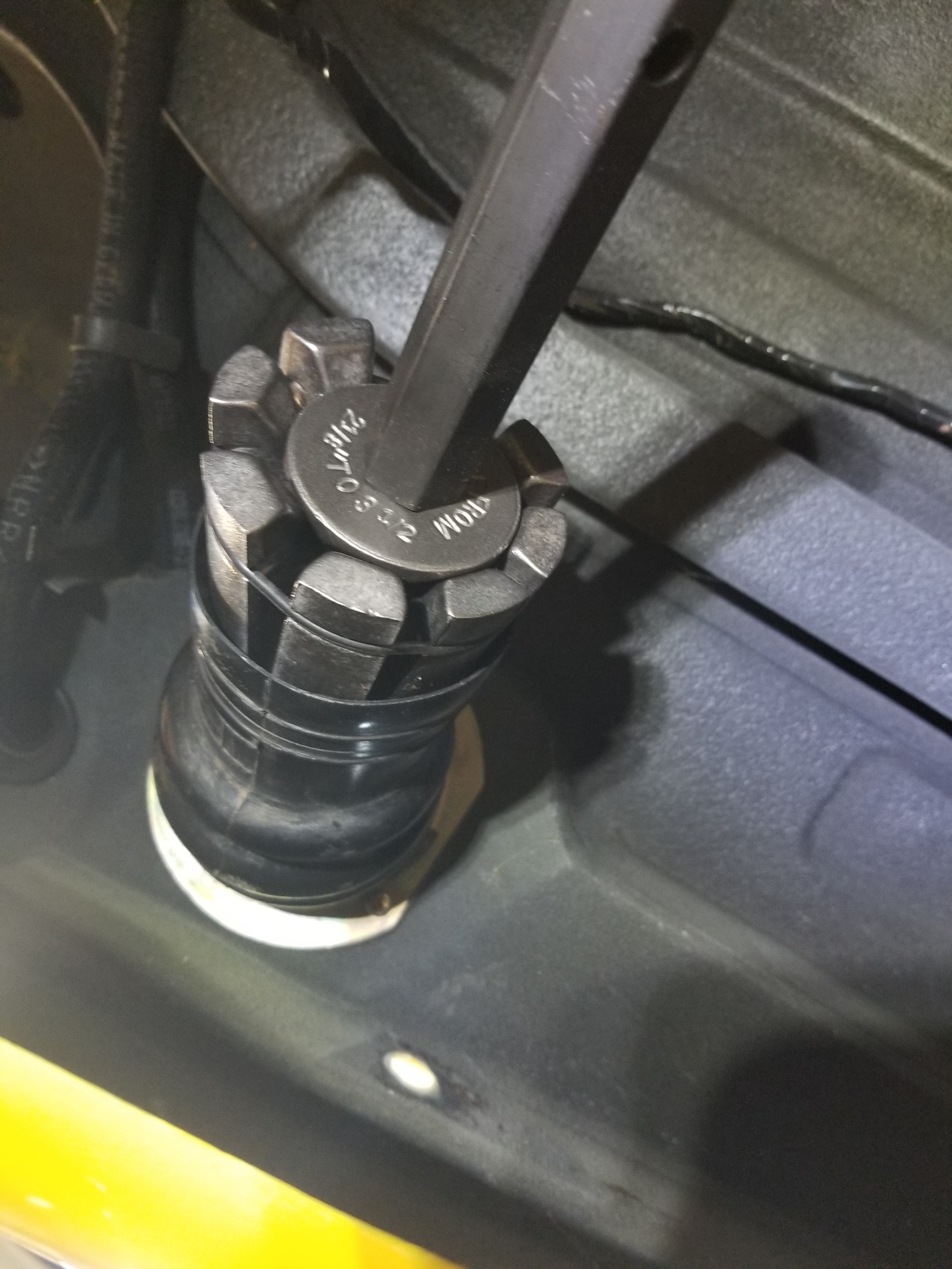
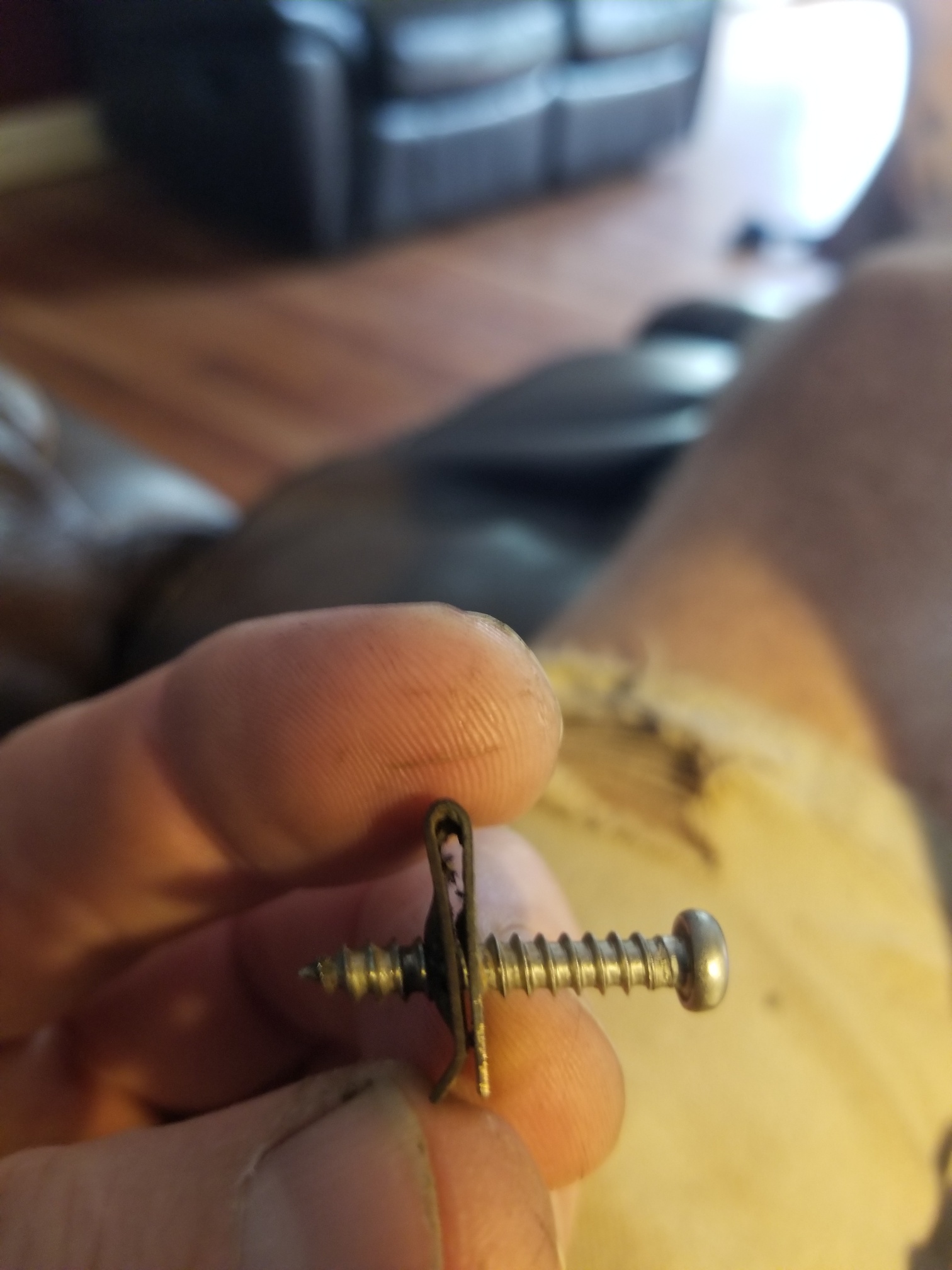
 1 point1 pointWorked on the fuel tank and vent lines today. Made gaskets for the wiper pivots Expander in the filler neck. A tip for the future, put the tank straps into the car body before lifting the tank into place. They are difficult to get in after the fact. I made some progress on the tank but I need a spring to keep the top front port on the tank from collapsing and I didn't have enough double wire hose clamps Does anyone know of a source the marker light screws? I would like to purchase them in bulk... BelMetric doesn't seem to carry that kind of screw

 1 pointThank you. On a side note, reading the FSM diagrams drives me nuts, since the wiring illustrations are from the terminal side of any given connector, compared to European format which is always viewed from wire side of any given connector. I'm already good at getting dyslexic with wiring, having to translate the pin locations in my head from the diagram to the reality just adds to the potential for error on my part. I always double-check my wiring anyway, with these it just takes even longer. OK - So I'm going to assume the pin configuration he illustrates is still accurate for the HEI then, with Gn going to the small leg on the HEI He doesn't actually list or show the physical wire transfer/connection within the module to the HEI pins: G (harness) = Gn-R (module) R (harness) = Gn-Wh (module) Mine has 2 Blk/Wh wires, middle one appears to be redundant - since there is no connection on the module side. Not sure if I should join the 2 together for the HEI, in case there is some reason the 2 are required.
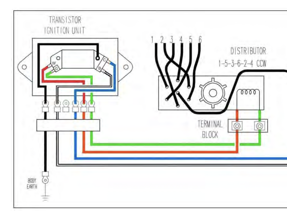 1 point1 point


Important Information
By using this site, you agree to our Privacy Policy and Guidelines. We have placed cookies on your device to help make this website better. You can adjust your cookie settings, otherwise we'll assume you're okay to continue.