Leaderboard
-
zKars
 Subscriber
 11Points3,770Posts
 -
HS30-H
Free Member3Points5,509Posts -
Captain Obvious
Free Member3Points10,081Posts -

wheee!
Free Member3Points4,607Posts


Popular Content
Showing content with the highest reputation on 02/04/2020 in all areas
-
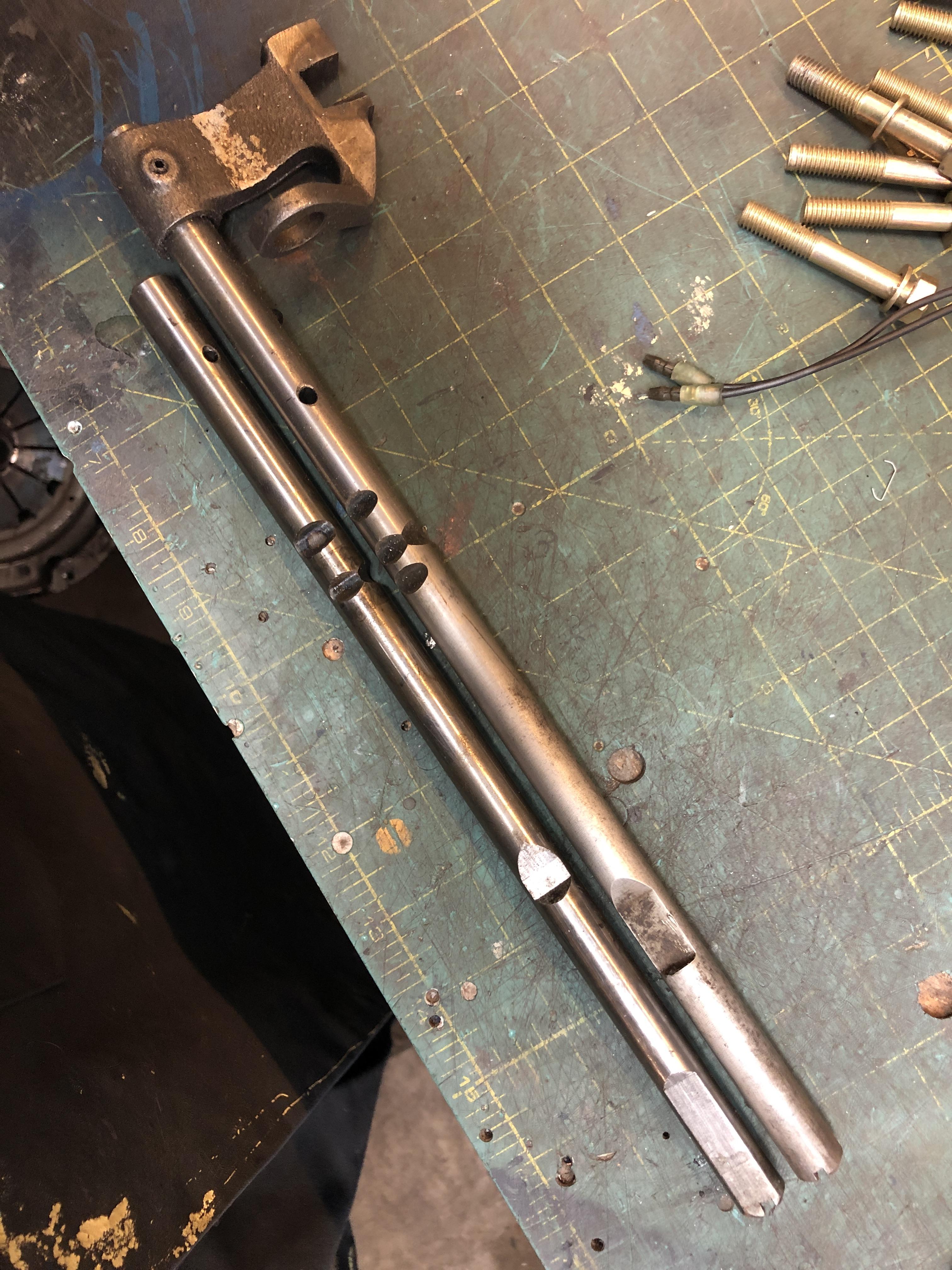
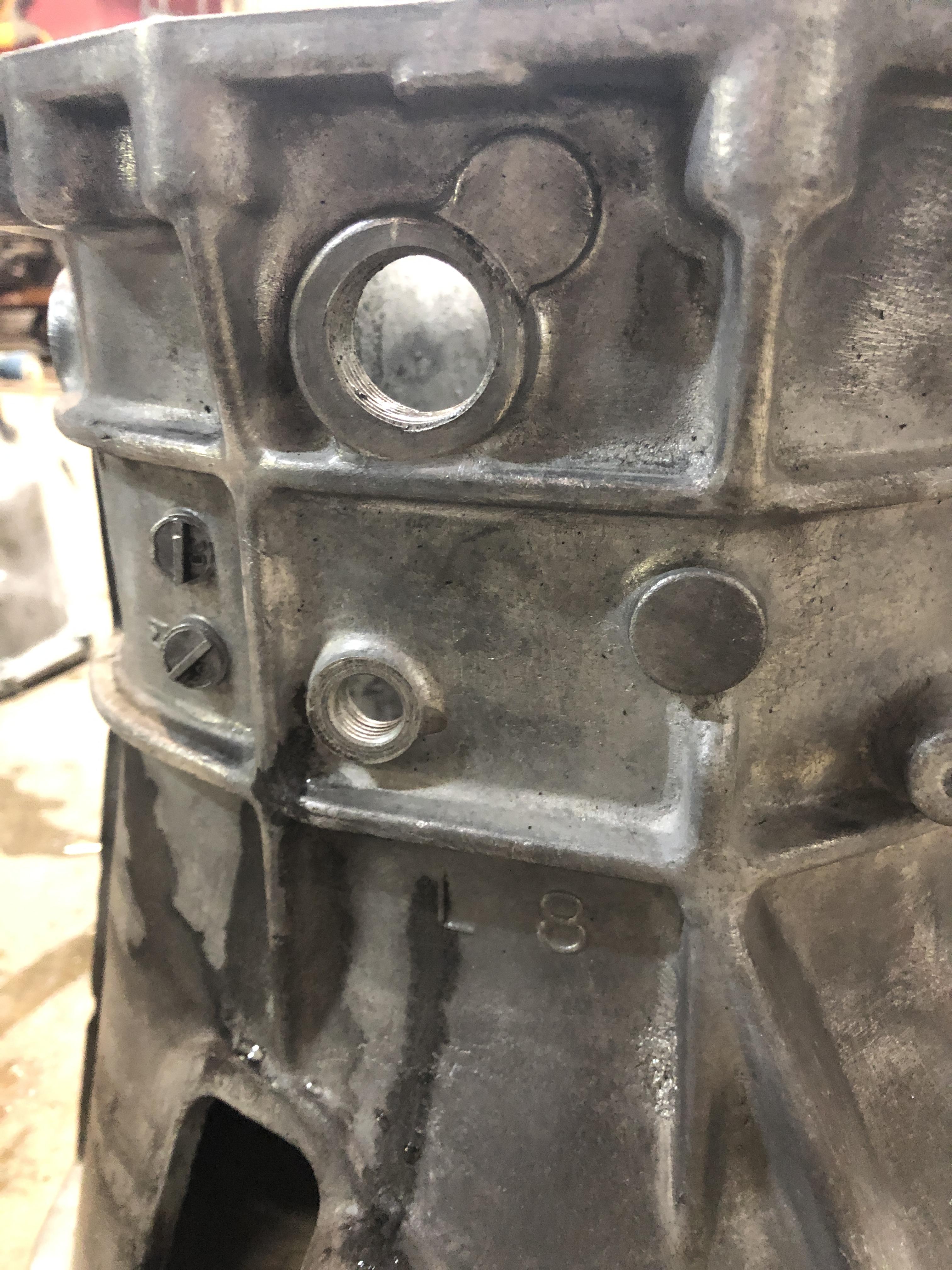
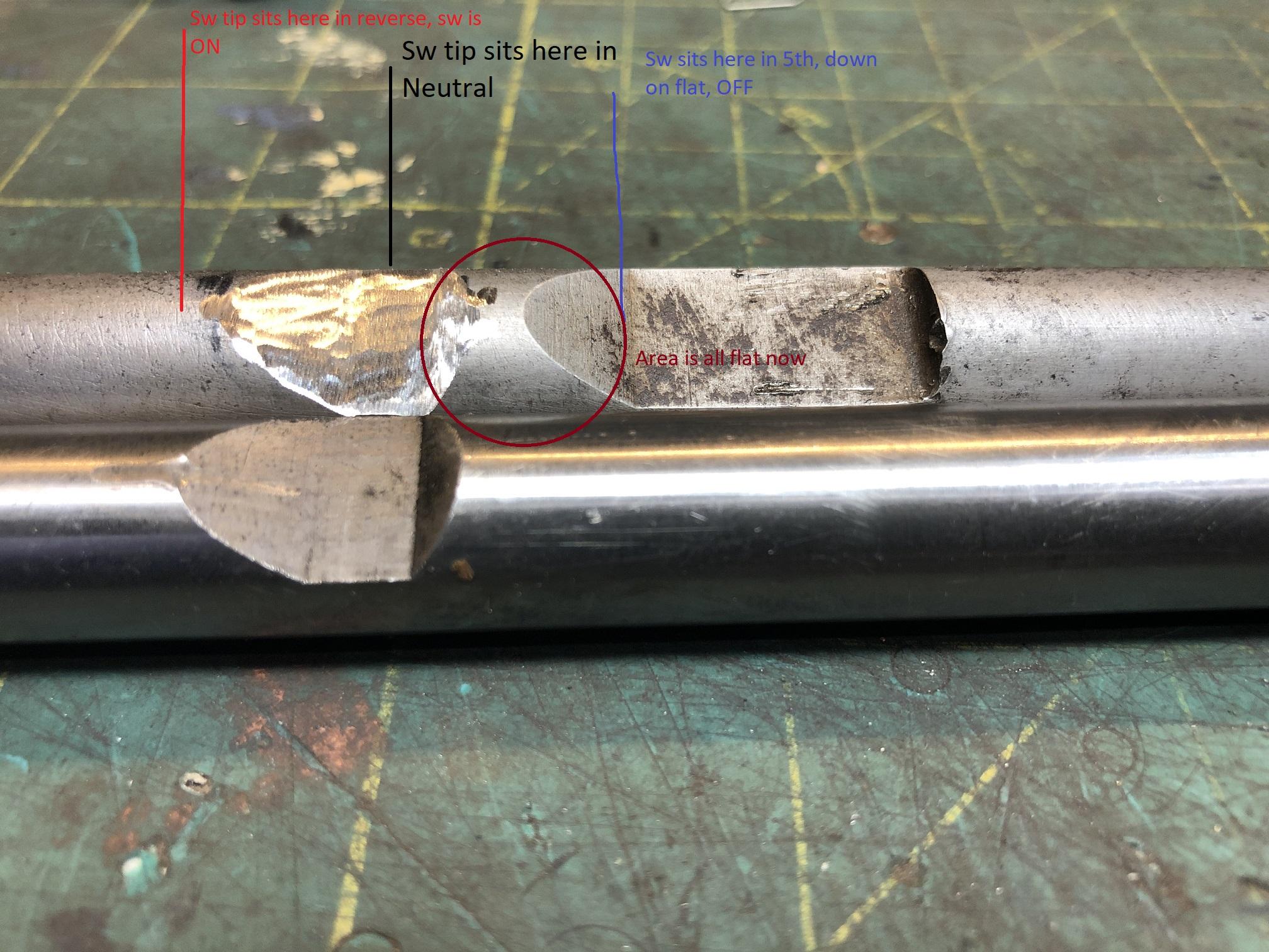
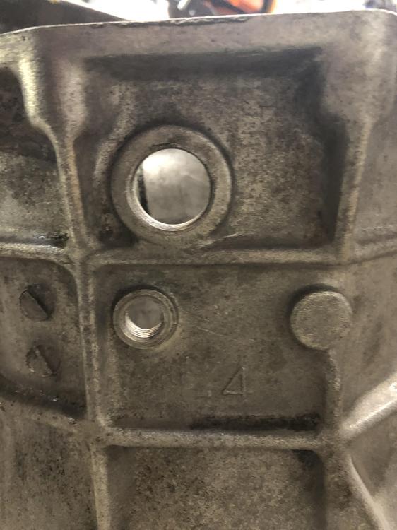
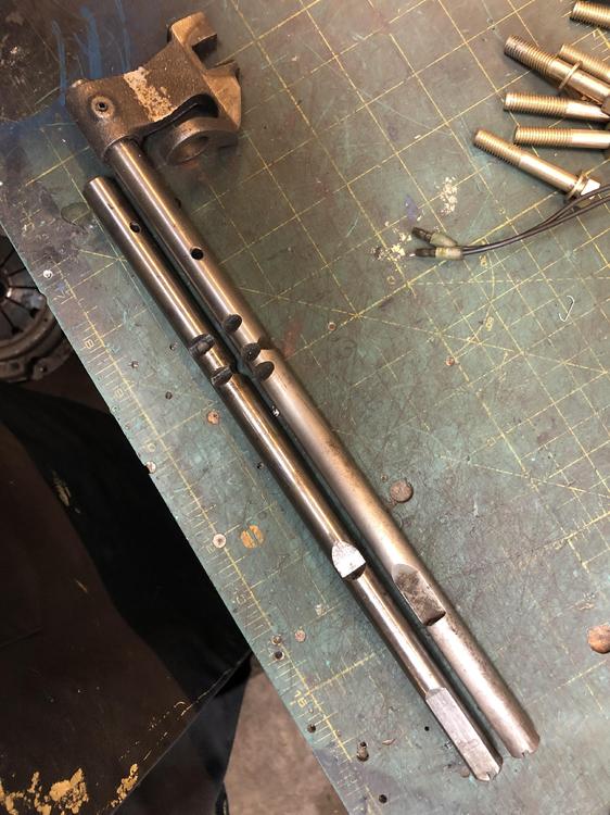
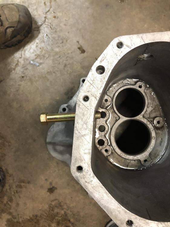
Last bit of ingenuity is in regards to using a 4 speed bell housing, and the issues it raises. Back a few pages, I spent a lot of time creating a way to may a 56mm hole into a 62 mm hole. I did my first test on a somewhat expendable 4 speed bell housing. It went better than expected, and I decided to put a 62mm front counter shaft bearing on this gear set to hopefully improve life span. So I of course feel compelled to use my new bell housing with the 62mm hole. The worst thing about the 4 speed bell housing, is that the reverse switch hole is in the wrong place. It's about an inch too far back. Location on a 4 speed \ Location on the 5 speed, further rearward The proposed solution is to make a new hole in the bell housing in the right spot, and plug the wrong spot. Not a terrible thing to do, it's a M14x1.5 threaded hole, I have a tap. When I looked closely at it, I noticed the hole does not pass through the case at 90 deg to casting. I threaded an M14 bolt in the hole to show you the angle. This doesn't look fun to drill or tap. I'm afraid if I go through at the wrong angle the tip of the switch won't hit the shift rod properly. So..... So I looked at the two shift rods. 5sp on the right/top. 4 sp on the left/lower. The depression where the tip sits when in neutral or 5th is of course farther forward on the 5sp rod (down in the pic is toward the front of the trans). Why not just extend the depressed area on the 5 sp rod farther back (up in the pic, sorry) so it ends at the same place as the 4sp rod and lets me leave the switch where it is? So that's what I did! I first created an identical pocket in the 5sp rod in the same spot as the four speed rod. Then realized that would/might keep the light on in 5th too, so I flatted the area between the old and new pockets. Just imagine that the full diameter bit in the middle is gone, and its flat all the way across between the two flats you see here. Now the switch will turn "on" when the tip rides up the slope from the flat spot to the rod full diameter, as the rod moves to the right (forward) going into reverse. Will stay down when going to the left to get 5th

 5 points
 -
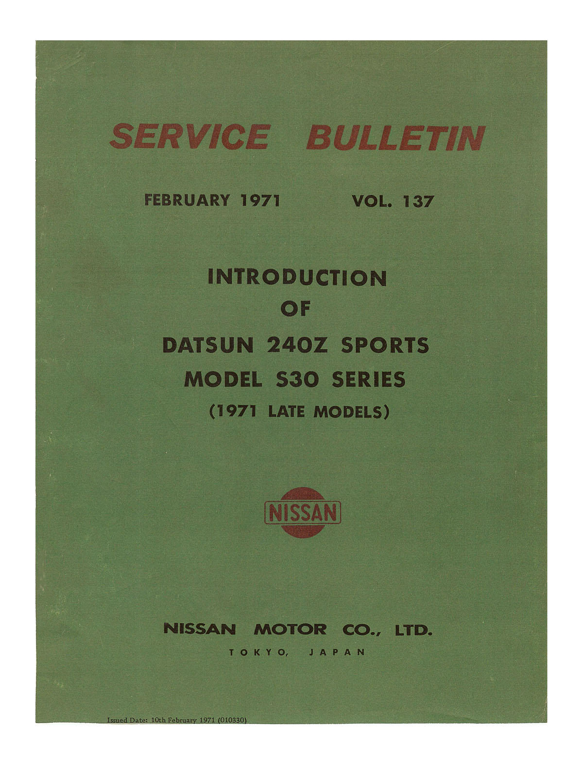
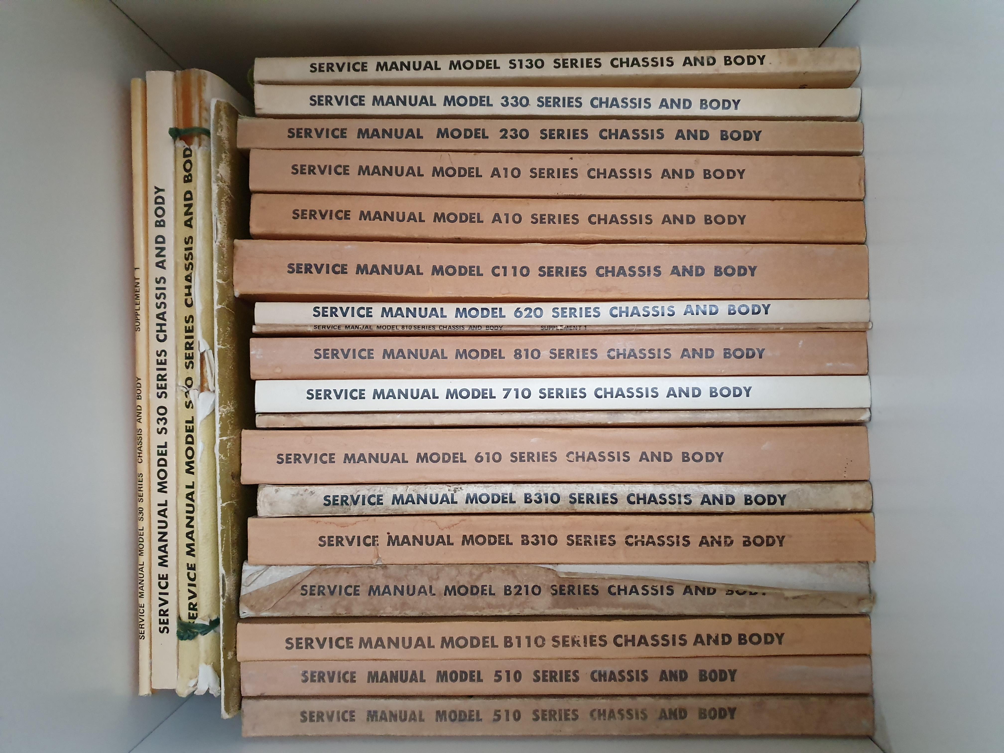
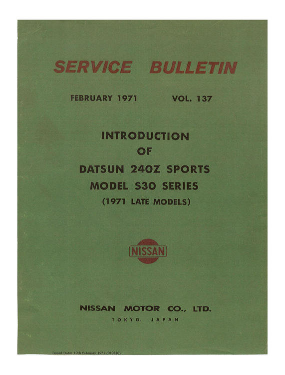
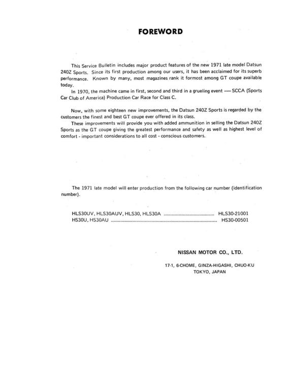
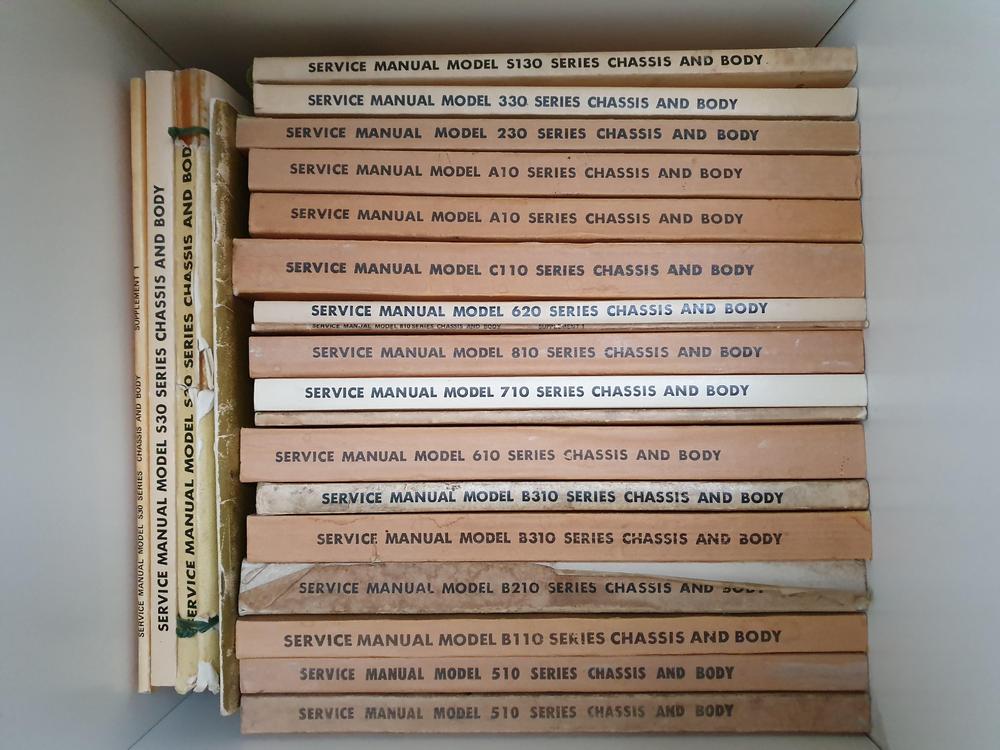
I certainly did not coin the term - I’m not that OLD! The use of Series designations to distinguish one model from another of various Marques, when confusion existed because of terms like “Model Year” - has been around and in use among auto enthusiast since I can remember. The E-Type’s for example used Series I & 2 when both models were sold with the same Model Year designation back in the early 60’s. (Some say Flat Floors) So nothing new there. Series designations were applied to the Datsun 240Z’s by enthusiasts not to long after Nissan sold the same model as both 1970 & 1971 Model Year vehicles, long before the Internet. We know there is a large overlap in the Registrations and Titles of 1970 &1971 Model Year examples. The first, second, third and fourth Series of Chassis Serial Numbers for Datsun 240Z’s are all specifically identified by Nissan in their Technical Service Bulletins. There are four specific VIN number series used to identify them.(one VIN series for Left Hand Drive and another VIN series for Right Hand Drive). Nissan issued Technical Service Bullets listing the beginning VIN chassis serial number series (Vehicle Information + Chassis Serial Numbers) as well as what Nissan considered major improvements to Safety, Comfort and Convenience of each - all introduced at the same time on the subsequent series. For HLS30 models: The First Series of Chassis Serial Numbers Sold to the Public - VIN’s HLS30 00013 The Second Series of Chassis Serial Numbers - VIN’s HLS30 21001 The Third Series of Chassis Serial Numbers - VIN’s HLS30 46000 The Fourth Series of Chassis Serial Numbers - VIN HLS30-120001 For HS30 models The First Series of Chassis Serial Numbers Sold to the Public started with HS30 00003 (from Oct.69) The Second Series of Chassis Serial Numbers - HS30 00501(from Jan 71) The Third Series of Chassis Serial Numbers - HS30 01501 (from Sep. 71) The Fourth Series of Chassis Serial Numbers - HS30 14001 (from July 72) Nissan listed some 17 or 18 specific Safety, Comfort and Convenience Features introduced on the Second Series of HLS30 production for North America, starting with VIN HLS30 21001 . These were not changes to minor parts during the production run, nor changes to part numbers made throughout the calendar year. These were improvements you got for buying the New & Improved Model being released and not found on the earlier one. See: SERVICE BULLETIN, February 1971, Vol. 137 INTRODUCTION OF DATSUN 240Z SPORTS MODEL S30 SERIES” (1971 Late Models) Likewise the New Model Introduction - Technical Service Bulletins - issued by Nissan list the significant changes for the third and fourth Series of production. Several of these Nissan Technical Service Manuals are now available in digital form on line.
 3 points
 -
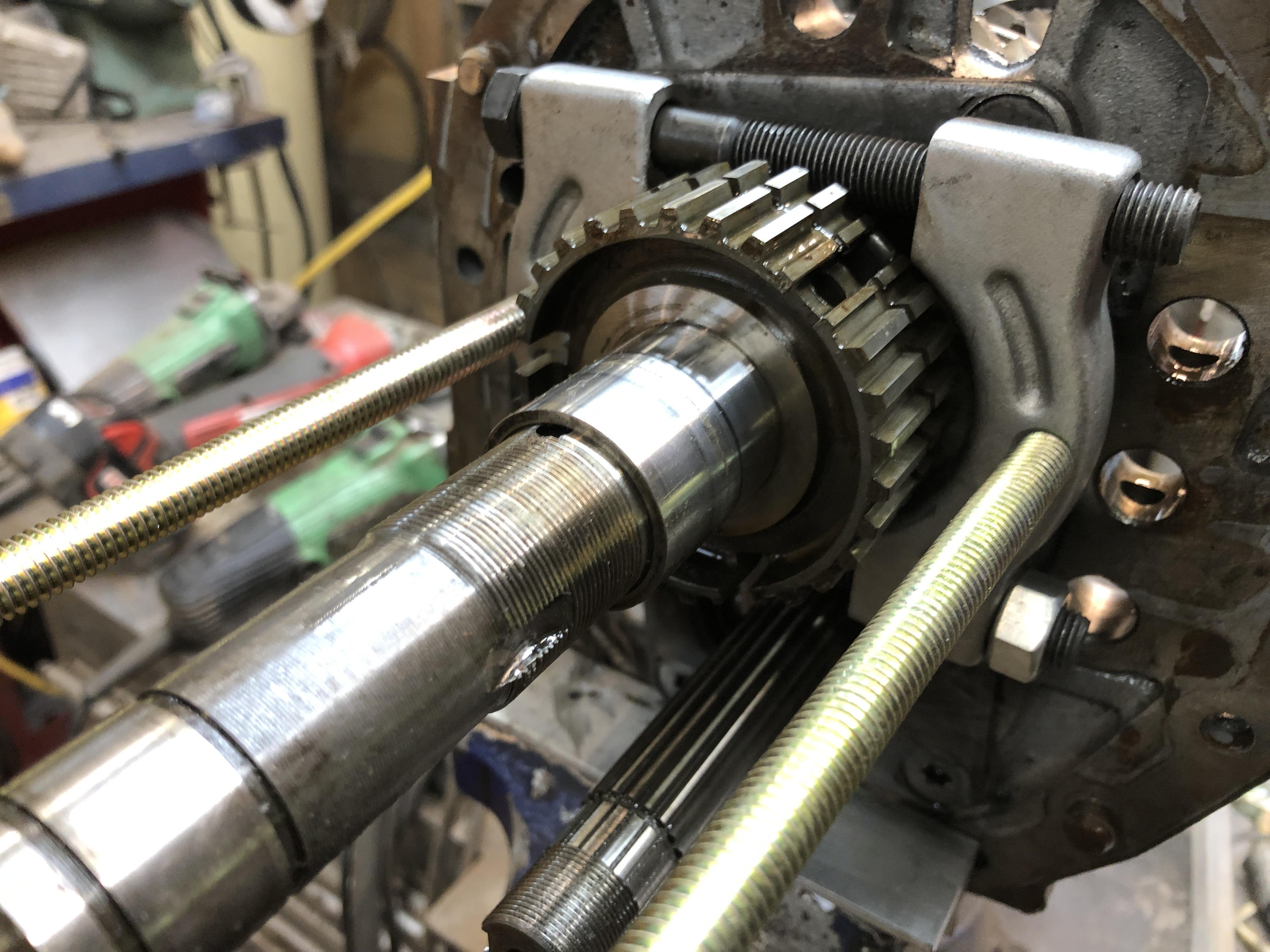
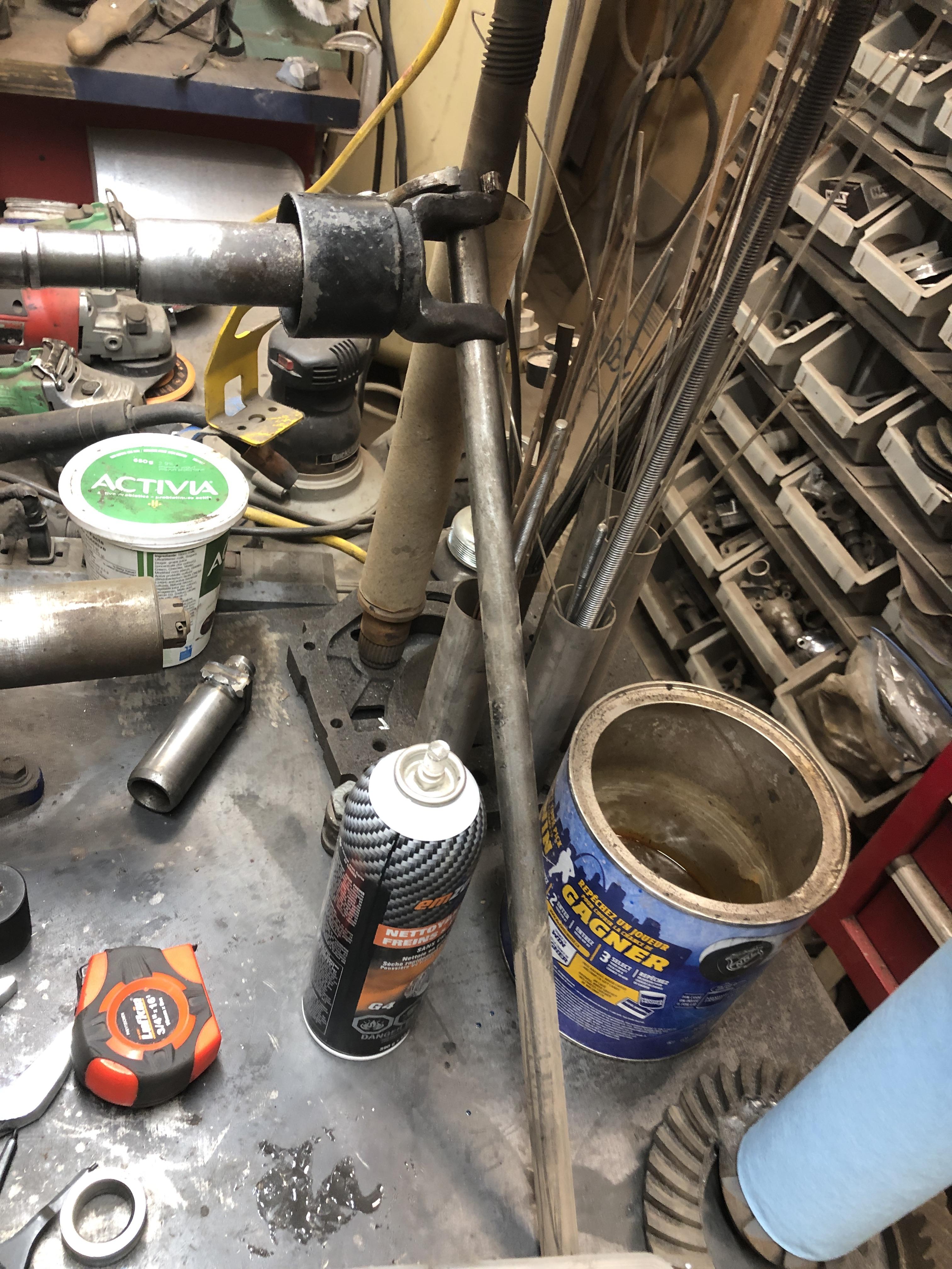
There is always at least one really grumpy part of every job, like spindle pins, and for this job, its a very tight bearing sleeve that lives under the 5th gear cluster. It is pretty easy to pull off, you use a bearing splitter in front of the 5th gear syncro hub , and a set of 18" rods to draw it all forward until the sleeve is over the threads, then its free. Back on is more grumpy. It sits just ahead of the threads on the main shaft for that big nut, so if you can get it far enough on to start the nut, then just tighten the nut down to drive the sleeve to the end. Well, not quite, the threads run out just before you get to the end. You can use the thick washer that goes on at this spot (the one with the ball or little dowel that sits in a groove to prevent it spinning) to add a bit of thickness to finish driving it all the way with the nut back on. I build a pipe with a hole in the end just the right diameter to hit the end of the sleeve. It slips over shaft that sits against the sleeve and lets me beat it in place with a mallet. You will need something like this if you can't get it on far enough to see threads that then allow you to use the nut to finish the job. This is not the pipe tool thing I built, but it is the world's deepest 38mm 1/2" drive socket. Probably about 18" long. I built to let me do and undo the big nut easily. Bought a 1-1/2 socket, cut it so just the hex was left, then welded it a 1-1/4 black iron pipe (standard hardware store gas or water line) and then welded the back half of a 1/2 drive socket to the other end.

 3 points
 -
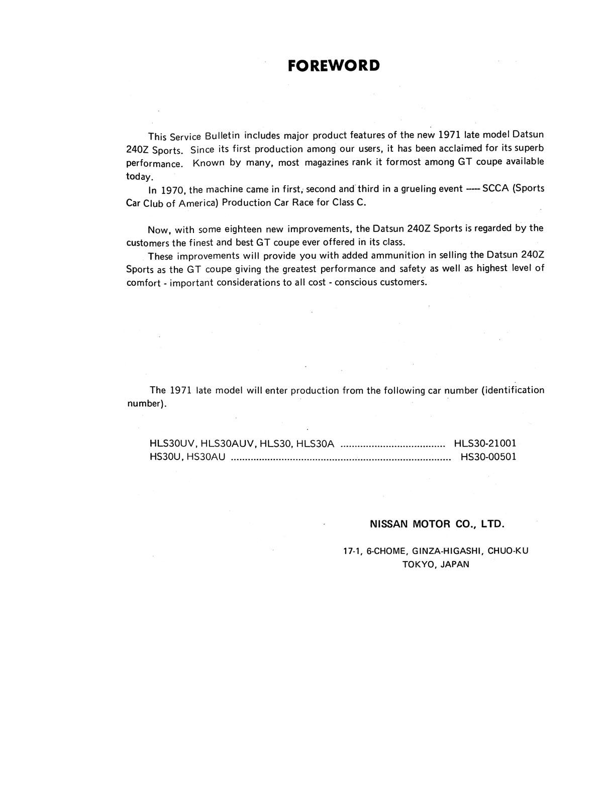
Well shocking but true, I actually assembled ONE whole transmission over the last couple of days with new bearings and syncro's. It is also the one I chose to do the hybrid mix of close ratio 5 speed gears (4th gear pair) with all the other 720 truck transmission gears to give me a .65 OD, while retaining ratio's for most of the other gears that still quite reasonable. See the posts a couple of pages back with the spread sheet. Anyway, the 4 gear main and Counter shaft gears and associated bits went right on with a hitch into the other wise truck destined parts. I was able to put the main and counter gear pair sets in and get the shafts pressed, well actually pulled, into the intermediate plate bears using the threaded nuts that are one both shafts, with a tube of just the right length. 3.375" long (1.25 ID tubing) works just fine for both. I had all the gears on both shafts, didn't do the front set separately like the FSM suggests, way too much work. Just takes a tiny bit of juggling of both shafts with one hand has you get the two shafts started in the bearings with a soft tap of a rubber mallet. Then tighten the two nuts (the big 1-1/2" one and the 27 mm smaller counter shaft) one, then the other to draw the shafts in sequentially until seated. Since the two shaft gear sets are mated yet, you can't throw both 1/2 and 3/4 into gear to lock the shaft, so you have to use an old drive shaft yoke and some pipe or whatever to lock the main shaft. There are plenty of "Special tools" in my arsenal now, and having old driveshafts to harvest bits from is critical. As is various lengths of pipe in handy diameters. I'll make a post later that shows all my "SFT's" as I call them (special field tools) and what I used them for.

 3 points
 -
This all makes sense now. Nissan called them the S30 Series, based on that we have the 1st Series, 2nd Series, 3rd Series and 4th Series of the S30 Model. Easy to understand how it got changed to Series 1, Series 2 etc. over the years.2 points
-
2 points
-
Seems crazy but it is an easy number to hit. Spending close to $200k for someone else to restore your car is not unimaginable. I could never do this car of mine if I had to pay someone else for the work. I’m no expert or craftsman and the finished product will reflect that. I’m okay with that. In the end, my car will hopefully still be worth close to what I’ve spent in parts and the better part of four years restoring.2 points
-
If only Nissan had given us some clues as to how they used the word 'Series'. Oh...
 2 points
 -
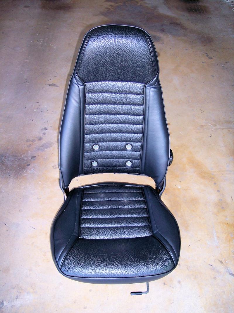
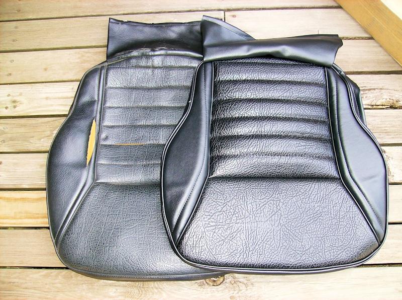
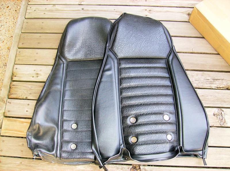
2 pointsThese are the replacement seat covers I purchased and installed about 10 years ago - pictured with the original covers for comparison. They came from Seatz, a company in CA, probably the most "original-like" covers available at that time. He does not sell retail. The last I heard he was selling thru MSA - a call to them would be in order to confirm. I used a hog-ring kit to install and similar to @240260280, added some sections of 1/2" thick upholstery foam to beef up various areas of the seats.
 2 points
 -
2 pointsThanks Guys. This is going to be a fun project and with Chris's help she should be a fine example of a 280 with its own special character.2 points
-
Looks like you have a separate problem of a leaking filler neck. Unless the fuel is all the way up to the top of the neck and is leaking from the gas cap. Take the cap off and see where the fuel level is. Fuel should never leak from the filler area. Here is the document that describes the heat soak problem.1 point
-
Yes you are!!! Ha, ha! I'm catching up to you Carl. I certainly didn't mean anything derogatory. I was reminiscing back to the e-mail blog days. Based on the Service Bulletin describing the "late model", it is very easy to see how this can be described by "series".1 point
-
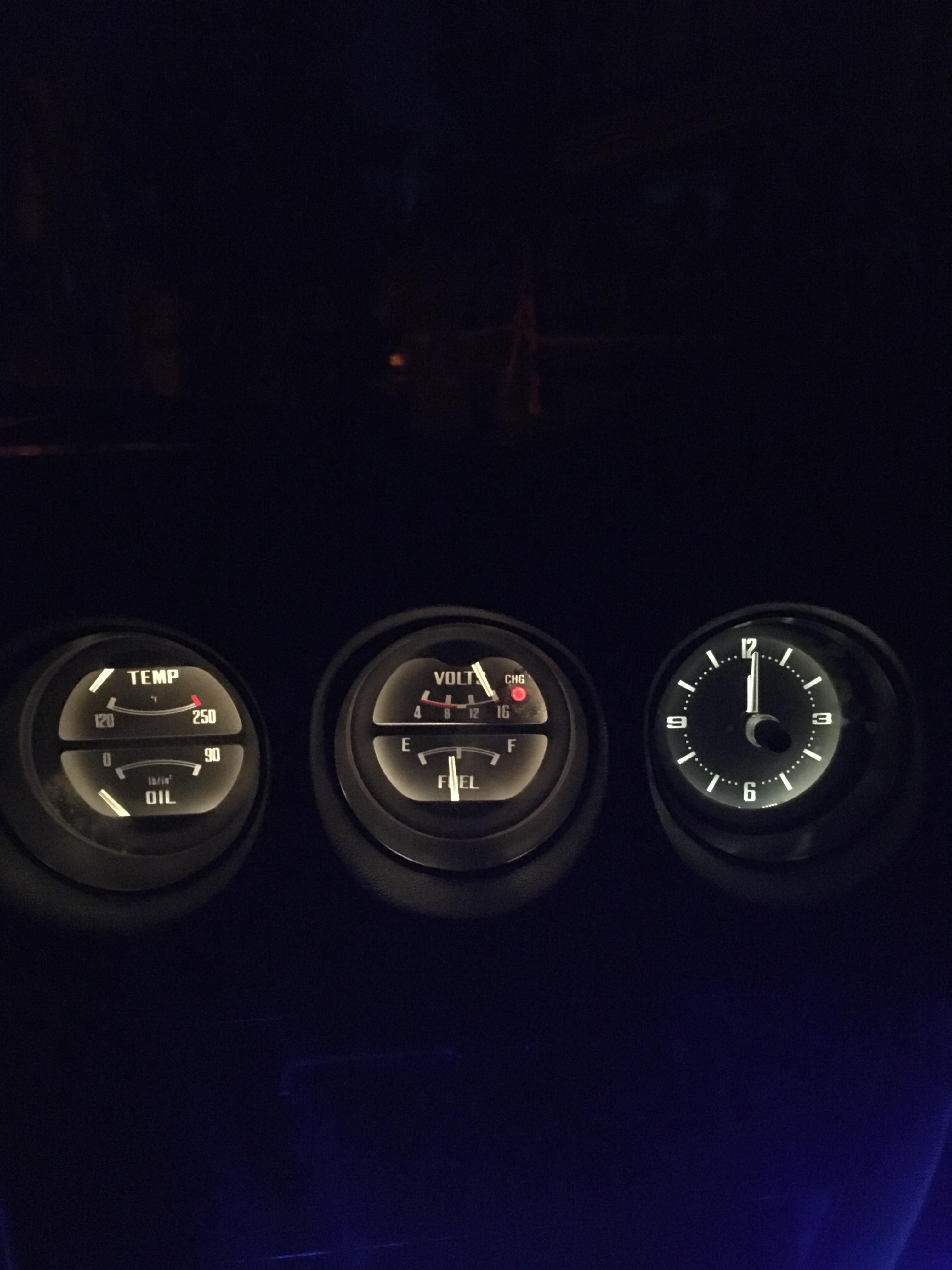
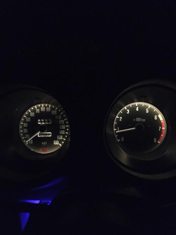
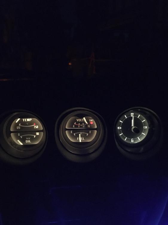
1 point2 Days ago my voltage regulator went out, producing an overvoltage and blowing all the lights that were on in my car except the headlights.Yesterday i started on the dash lights first and removed all the gauges and disassembled them, I took out all the green light filters and replaced all the bulbs and this was the end result. Much brighter gauges and A LOT easier to see now! EDIT: Ignore the oil gauge ( I have run a oil line into the car to a mechanical gauge to get a better reading as replacing the oil sending unit last year ended up saying no oil pressure on the stock gauge)
 1 point
 -
This is messed up. Vin # to 021000 in May of 1970???? My July 240z is Vin # 0007032. Then it jumps to Jan 1971-----what about June, July, August, etc.???? Just saying there's a big typo here.1 point
-
1 point
-
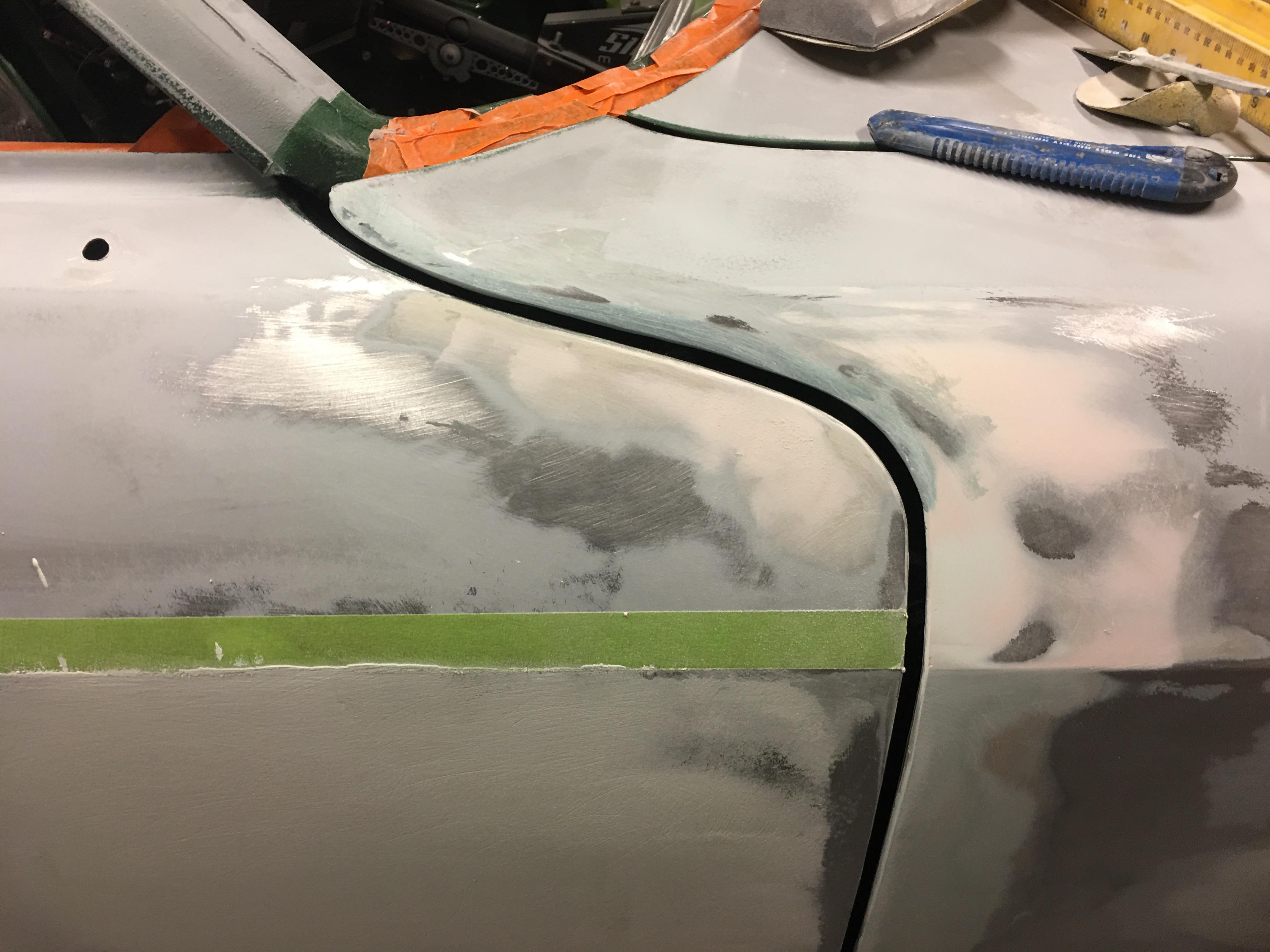
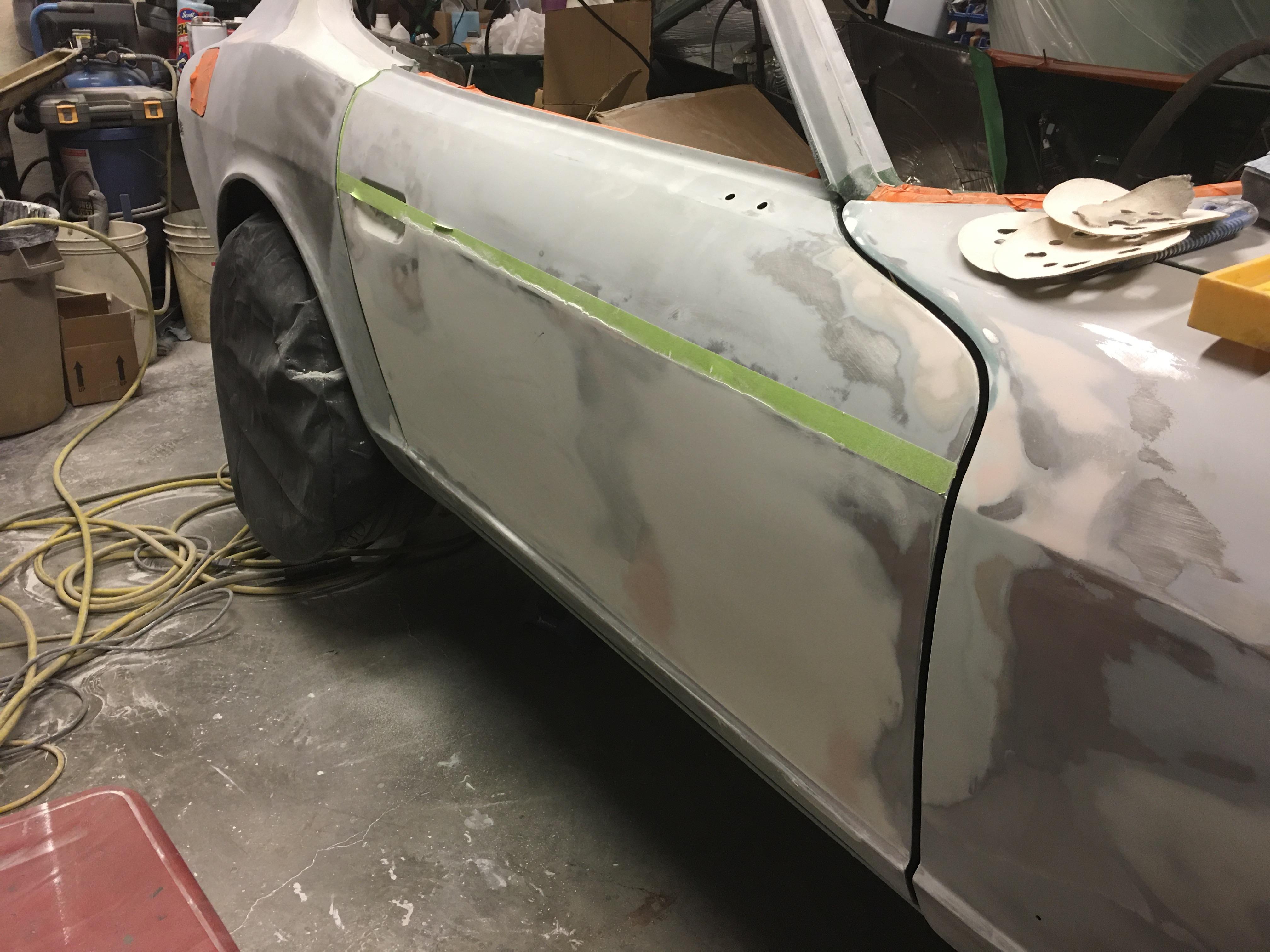
1 pointMove along, nothing to see here... Hours and hours of sanding off all the filler I put on.... the door is finally flat through the main part. Just the top edge and the handle area to finish out. The gap at the fender and door kept me awake so I carefully filled the edge with short strand fibreglas. Surprisingly tuff as I tested it’s strength and couldn’t snap it off by hand. I guess we’ll see how it holds up!

 1 point
 -
54436-E4100 Bolt-Transverse Link - Bolt that secures the front control arm to the subframe(note the color) NLA from Nissan US 01221-00211 Nut-Hex Lock L - left tie rod end lock nut- NLA from Nissan US 08911-34410(A) Nut-Rev idle shaft - Early 4 speed trans also used on the 3N71A automatic trans to lock the shifter in place. However more familiar as the right tie rod end lock nut- NLA from Nissan US1 point
-
1 pointWelcome aboard! I suspect if you're a friend of Chris', you're already a special character. This is your place, right?
 1 point
 -
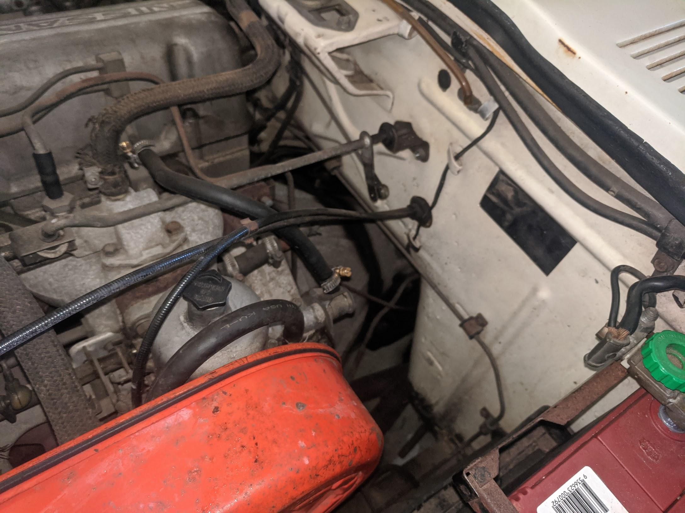
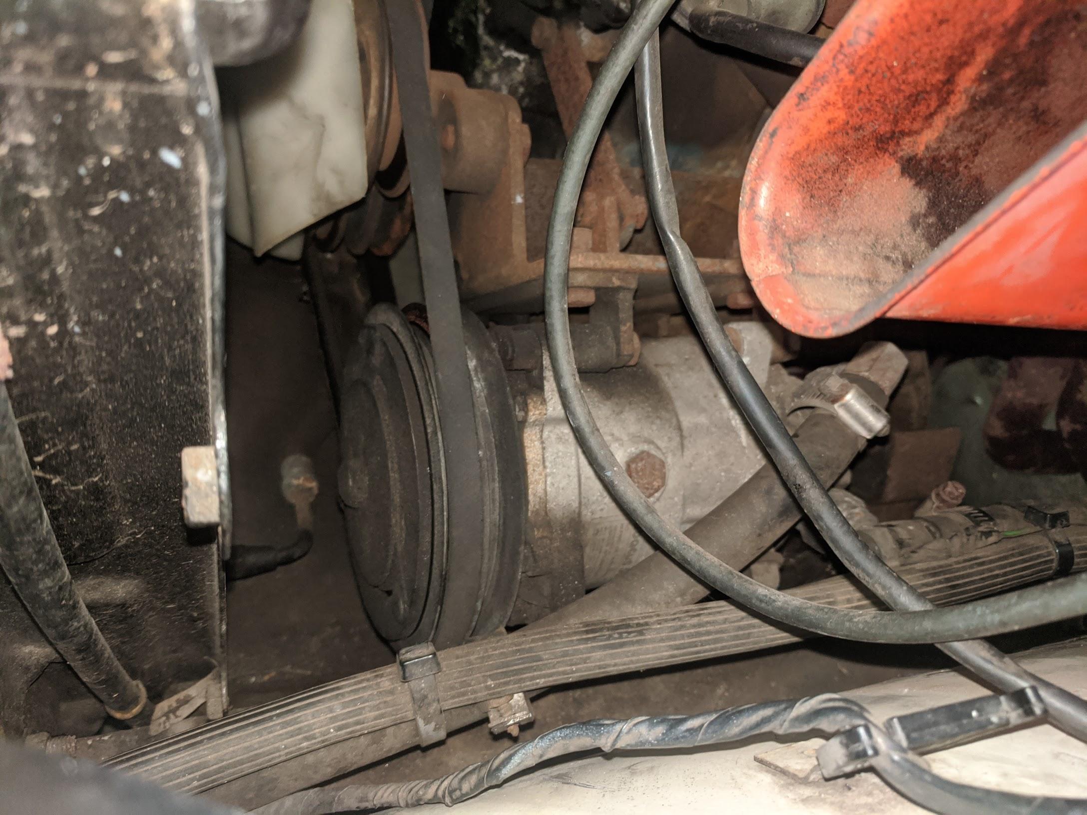
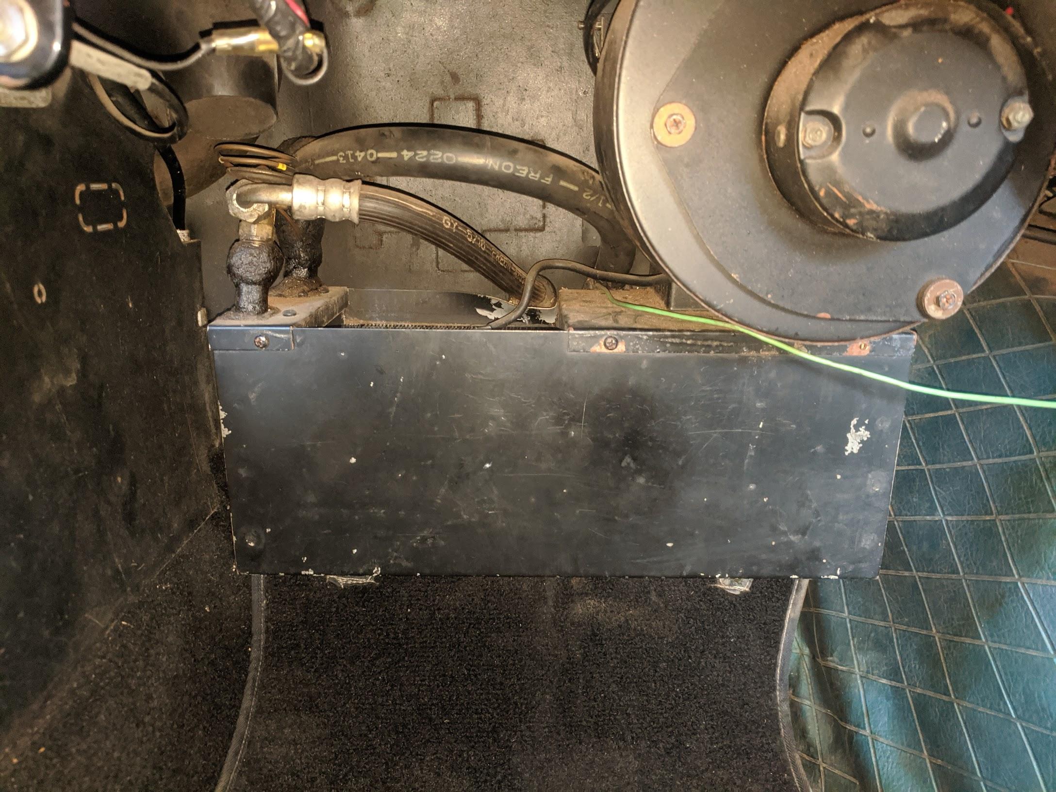
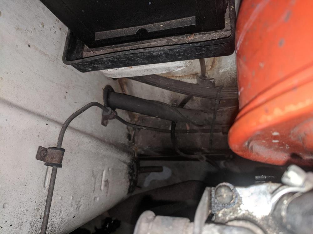
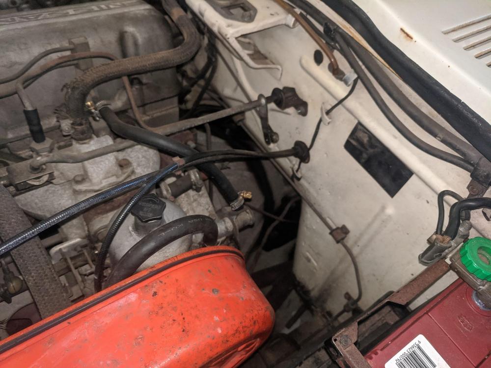
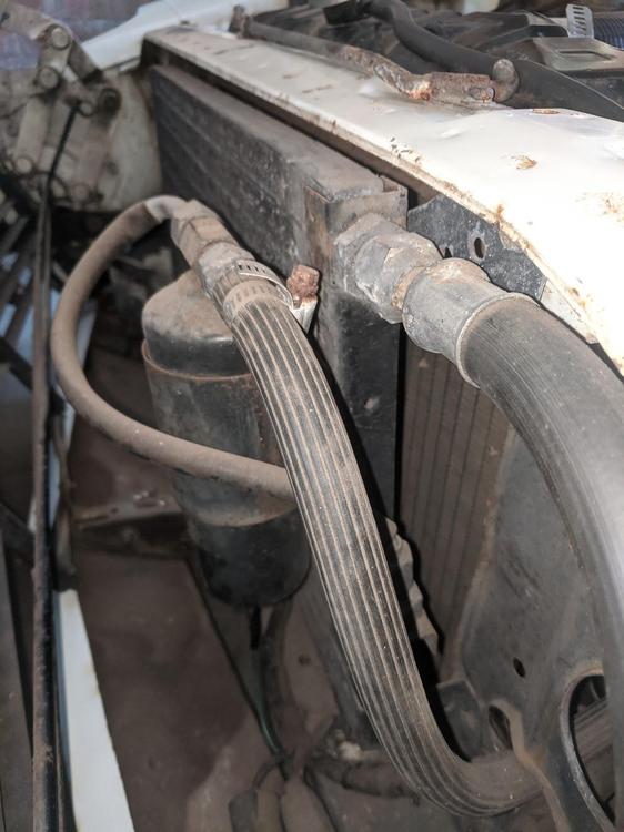
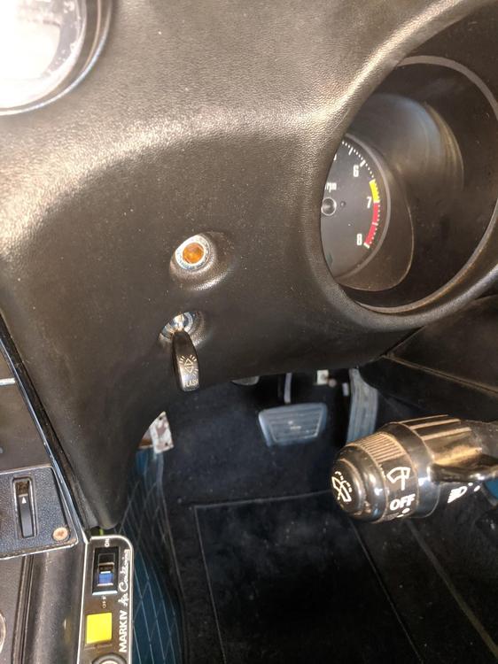
My dealer fitted aircon in the 71 240z... Controls sit on side of console. Passenger foot well. Compressor sits on bracket under airbox. Condenser and radiator set up. Firewall doesn't use piping like the Fairlady Z models. Instead there is 2 holes under the battery.


 1 point
 -
I wish there was reproduction carpets exactly in the style of the originals like your photo Kats. I think my 73 240z I bought in the late 90s had the original carpets still but they were begging to disintegrate and everytime I'd move them in and out of the car there would be black bits of carpet left all over the floor. It was frustrating, but they fit perfect in the car. So far no aftermarket floor carpet has fit as nicely.. I never knew they had an inspectors tag on it either. Cool.1 point
-
And I'm trying to get across the point that factory rated outputs are for *bare* engines. A smog pump-equipped, retarded timing anti-emissions L24 simply cannot have the same real world output as an L24 that is not similarly encumbered, even if they *do* have the same output written on their engine bay tags. And gear ratios and diff ratios very much DO have an effect on The Package. The above - different - L24s will perform quite differently in character when they are part of a car, and especially so when one is attached to a wide ratio 4-speed and 3.3 diff, and the other is attached to a close ratio 5-speed Overdrive and 3.9 diff. 432 and 432R were equipped with that close ratio 5-speed and a 4.44 diff with LSD. Again, a package that was well balanced and aimed at the sporting driver.1 point
-
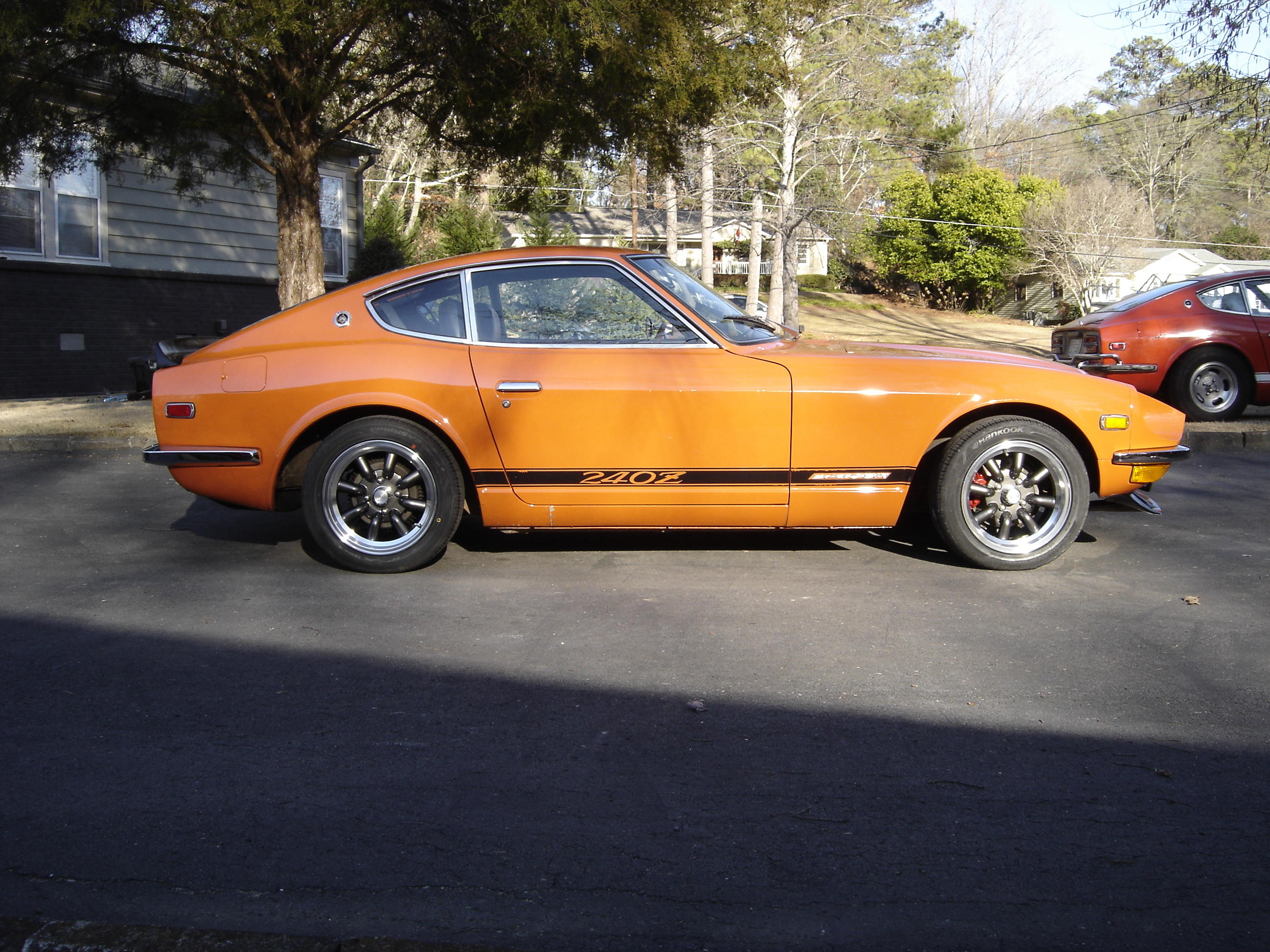
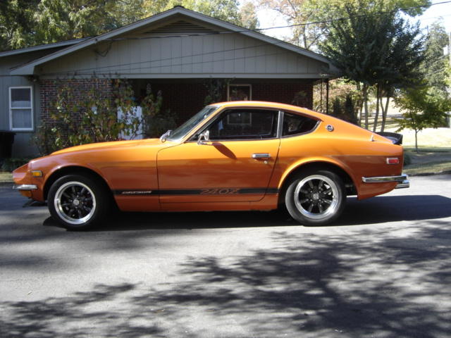
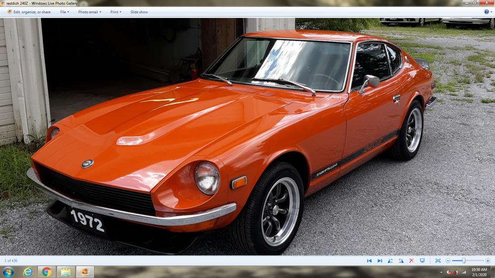
Mine has around 75,000 by now and has the original paint and interior. I have those same 240Z Amco floor mats as you have. Check out how different the paint looks in different lighting, it looks like a different car but it's the same one!

 1 point