


.JPG.cfcada9cf1c1b502df3f5f2f2ca3ff36.JPG)

SteveJ
Community Member
-
Joined
-
Last visited
Everything posted by SteveJ
-
https://www.youtube.com/
-
I suggest you start another thread about the transmission, and when you do make sure you clarify what is going on. You can shift a manual transmission without a clutch (though not as a beginner). Race drivers tend to use the clutch only to get the car into first. Since it will go into first with the engine off, it sounds like the transmission will still shift. It could be an issue with the master/slave cylinder or the clutch fork. The latter is rare, but they can break.
-
With the stock alternator, you will need an external voltage regulator. The blue NGK wires don't bother me, but then again, I find that NGK makes good products, so quality is valued over aesthetics.I also sent a message to the director of the Z Car Club Association to see what he might have for an email address for them. I'll let you know if he responds. He's usually pretty good about getting back to me.It can be a challenge to keep a club website going. I have been doing some internet stuff for the Georgia Z Club for 8 years now, and I admit that I have slacked in some areas on keeping things up to date. Did you try sending the ZCCNV a message on their FB page? https://www.facebook.com/zccnv/ @Diseazd Can you reach out to Eiji and see if he can provide a name/number to help out Jim?If you haven't already, join the Z Car Club of Northern Virginia.Well, you're about 2 hours away from me. Would you like a second opinion on your car? I have been taught by some very good people like @240260280 about how to balance/adjust the carburetors. I might even be able to convince some other Z friends to come over, too.Why not just use the choke? The hand throttle wasn't for cold weather starts.The condenser is a radiator (or air-to-air intercooler). As the air compresses, it builds up heat. When the compressed air passes through the condenser, the fan is moving air past the coils and pulls the heat out of the compressed air. With the cooler temperature, the water vapor in the compressed air is more likely to condense. If you can trap the water as liquid in the tank, there is less water vapor later on to try to trap as you are using the compressed air.I know Rodney well. He lives a few miles from me, and we have hung out together several times. I first met him at The Mitty at Road Atlanta around 8 years ago or so. He had the future ZMW on display in the Vendor Village.Cool. Who's your friend in Atlanta? I live half an hour away from Road Atlanta.Did you look closely when you took that photo of your gas tank? I don't know where you saw someone say there isn't a drain plug.
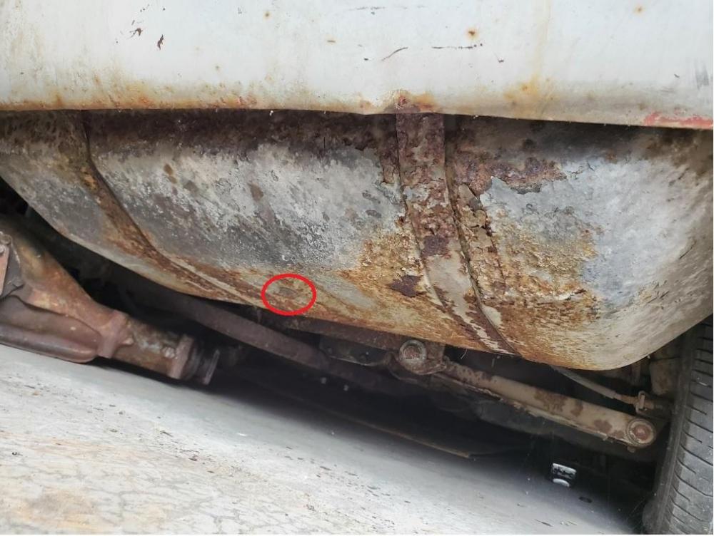 Turn by hand first. If you try with the starter, you could tear up the flywheel and/or starter. Why break more if you can avoid it? There is a gas tank drain. I suggest you look under the tank. With the state of corrosion in the engine bay, I shiver at the thought of what the car may look like underneath. Don't worry about a source for gas now. You need to do plenty before you get to that point. For instance, those carburetors need to be taken apart a cleaned thoroughly. Lord knows what condition the float bowls are in. Keep in mind that there is a return on the fuel rail, so you want to catch that gas. You may want to get a Haynes manual as a secondary source to the FSM. I found there are some photos in that manual that capture some things the factory manual doesn't. How much experience do you have with working on cars?It's a MS relay board. He has another thread with the same title (different forum) here:Sure you can cut it out. It's your car. Will the car start without that? Did the car run when you bought it? We can't tell from the photos you posted what you have under the hood. Where else does it go to? It goes to the MS ECU, the fuel injectors, and the electric fuel pump. Do you have all of those components? If you want to go back to stock, I suggest you go to the downloads section on this website and download the factory service manual for the 71. Then start by reading through the EF section to familiarize yourself with the components you are missing.I will add that the relay board certainly has seen better days. It should have been mounted inside the passenger compartment. The person who installed it chose a very poor location for mounting.I looked at the other thread. It's not stock. It's a MegaSquirt relay board for fuel injection. https://www.diyautotune.com/product/megasquirt-relay-board-assembled-unit/It's something a previous owner added. The pictures aren't that good of quality, but it looks like some plug-in relays and a terminal strip.I would think it would work if you have the CG of the car in the right place, though you may have to contact the manufacturer to be sure. I'm sure my lift could do it, and it has the same rated capacity as that one. Would the open end be under the garage door? That could affect hood clearance if the hood was open. One other possible issue could be ground clearance between the bottom of the car and the lift. I have two 2x12s for my car to drive on to prevent scraping exhaust (2.5 inch) on the cross supports. The track of my lift is not nearly as wide as the Dannmar. For that matter, I'd have to wonder if the pads on the Dannmar would be hitting the pinch welds on the Z with the width of the lift.The challenge with the last one is the piston in the middle. I say that having a scissor lift with a piston in the middle. It will interfere with oil changes and possibly oil pan and transmission work.For me, I clicked on the photo and saved it to my computer. Then I opened up the saved picture and zoomed in.
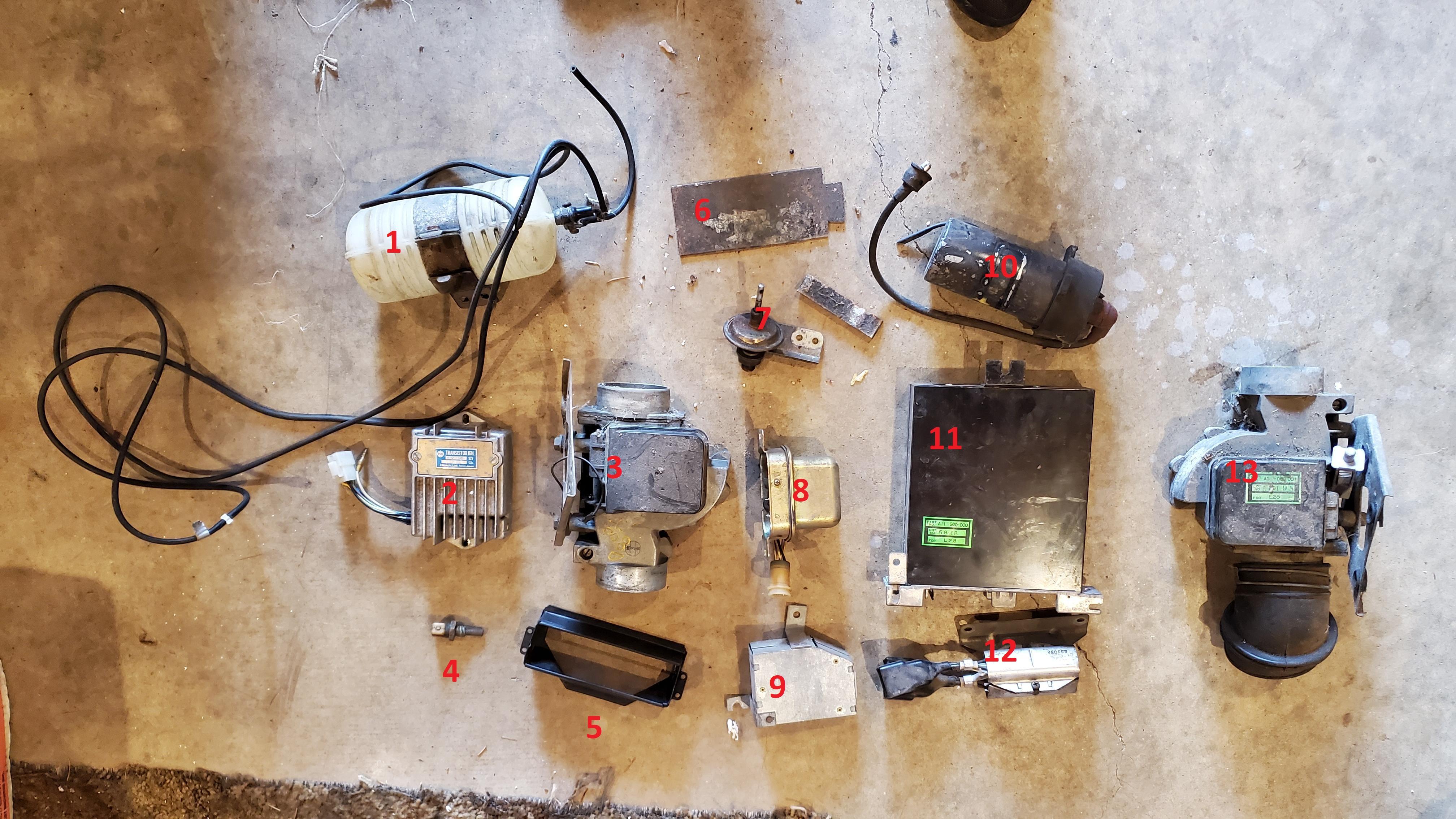
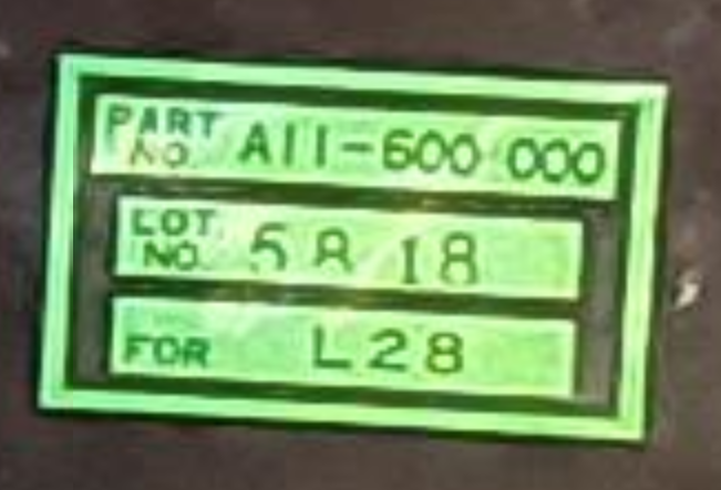 Vacuum bottle for AC Transistor Ignition Unit AFM - I think Water temp switch - I think ??? ??? Dashpot - Maybe a vacuum advance Voltage regulator ??? Ignition coil ECU (Label says Part number A11-600-000) ??? AFM
 We all have our ways of dealing with stress and grief. Frankly, I don't see how your way is creating an imposition on anybody. Just work through it.


Important Information
By using this site, you agree to our Privacy Policy and Guidelines. We have placed cookies on your device to help make this website better. You can adjust your cookie settings, otherwise we'll assume you're okay to continue.