.JPG.cfcada9cf1c1b502df3f5f2f2ca3ff36.JPG)

SteveJ
Community Member
-
Joined
-
Last visited
Everything posted by SteveJ
-
And it's a very good idea to orient the battery the way Nissan designed. I had a battery with the positive toward the engine, and it wasn't secured properly. When the battery moved, the positive terminal made contact with the engine. Lots of smoke and burnt wires. With the way Nissan oriented the battery, the positive is less likely to come into contact with ground.
-
Your battery cables are probably swapped. Again, the way to confirm is to measure voltage from the positive terminal of the battery to the body and from the negative terminal of the battery to the body. If the battery is connected properly, you should see 12VDC from the positive battery terminal to the body and zero from the negative battery terminal to the body. Nothing good ever comes from crossing the streams...
-
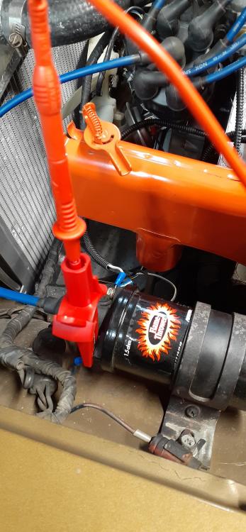
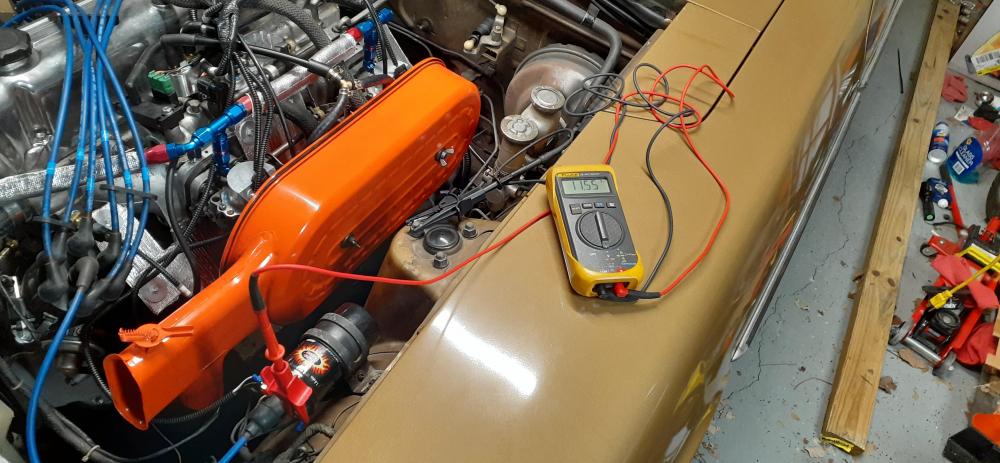
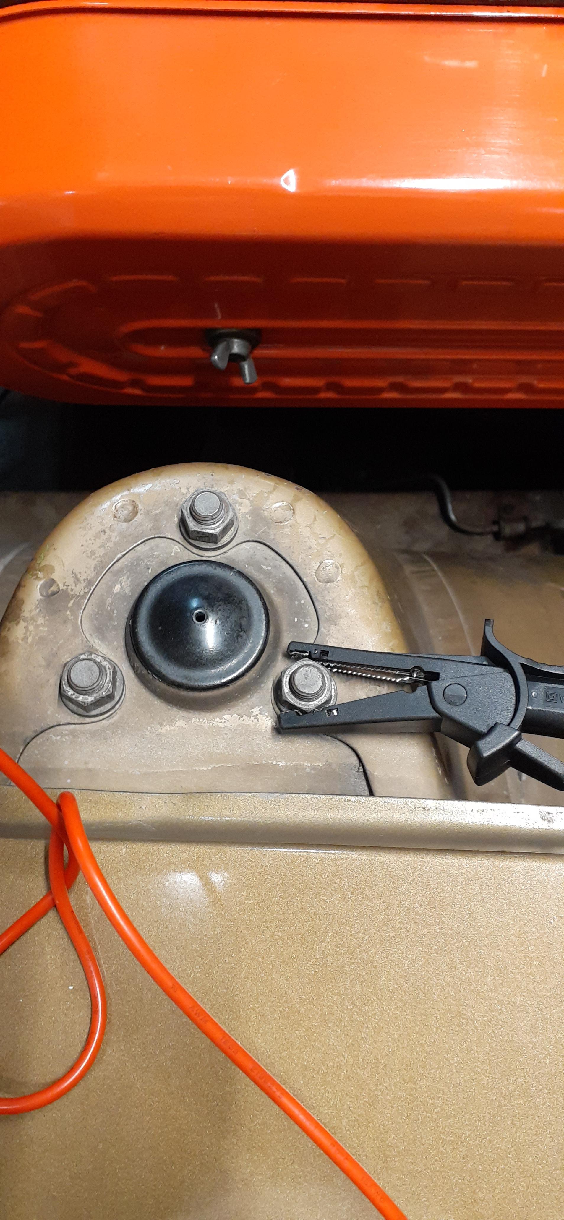
I responded to your other post: As I said in the other thread, you are leaving out important context of HOW you are measuring the voltage. Where are you placing the positive and negative probes? Adding to this thread, what is the voltage from the positive battery terminal to the body? What is the voltage from the negative battery terminal to the body? I have never heard of anything good happening to a 280Z if the battery terminals are swapped. Here is an example of checking for voltage at the coil. For your issue, you could put the positive probe at the black/white wire at the ballast resistor.
-
No. The HEI would replace the Transistor Ignition Unit (TIU). The ignition relay takes the burden off of the ignition switch. Instead of all of the current for circuits powered in the ON position going through the ignition switch (and decreasing the life of the switch), most of the current goes through the ignition relay that is cheaper and easier to replace should it fail. Your measurement has no meaning without context. What position was the key in? Which probe (positive and negative as plugged into your meter, not color) was touching where? The white/red wire should have 12VDC to ground all of the time. The black/white wire should have 12 VDC to ground with the key in the ON position. (Notice that I say "to ground". This means the negative probe of the meter should be touching the chassis of the car. You can use an unpainted bolt connected to the body for this.) If you are touching the negative probe to the white/red wire and positive probe to the black/white wire, you could see -12 VDC displayed on your meter if the key is not in the ON position or if the ignition switch is bad. The black/white wire at the ballast resistor is electrically the same as the black/white wire at the ignition relay. For the ballast resistor, the black/white wire runs from the ignition switch, through connector C-3 (and C-2), and over to the ballast resistor. If you have the key in the ON position, as I said in #2, you should see 12VDC to ground on the black/white wire on the ignition relay. If you do not have 12VDC to ground there, you will likely not have 12VDC to ground at the ballast resistor. At that point, it is likely that you have a bad ignition switch.
-
I happened to find the manual (right on the floor of my garage). It doesn't give any info on country of origin. According to the FAQs at https://www.gregsmithequipment.com/General-FAQ "Most of the products sold by Greg Smith Equipment are manufactured in Asia. We do not hide this fact. We could not offer the incredible pricing on all of our equipment if it was made in North America."
-
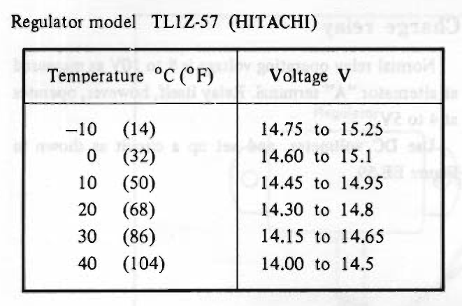
Better yet, look at the EE section of the FSM. If you have an original points-style VR, the procedure starts on EE-23. Keep in mind that the voltage is dependent upon engine speed and ambient temperature. The chart in the FSM is for 2500RPM. You said the voltage was 14.45 @ 2000 RPM. Given that the temperature was probably between 50 and 60, I will repeat that I don't see a problem. With only the engine running, you're not pulling much current aside from topping the battery back off and firing the ignition. Swap the brake lights and turn signals to LEDs, and you probably won't see the ammeter needle move much of any time.
-
Unless modified by an owner, 70-77 have an external regulator.
-
Um...don't mess with it. I don't see anything wrong with those numbers or with the ammeter action.
-
By Source, Fair use, https://en.wikipedia.org/w/index.php?curid=982958

-
Try emailing sales@gregsmithequipment.com. I bought my scissor lift from them. If I can remember, I'll look for the manual. And for @Av8ferg, I had a good experience with Greg Smith Equipment. I went to them because they are local to me. They actually messed up and sent me a better lift than what I ordered. I let them know, and they didn't charge me the difference. The only downside about that for me (if you want to consider it a downside) was that I had to get a 30A receptacle and circuit breaker installed for that model.
-
Mouser shipped my order, and they upgrading the shipping to UPS 1-day for free. It's almost like someone working the order is reading this thread. If so, THANK YOU!
-
I did my own. The @Zs-ondabrain kit (sold by MSA) has two positives and one negative.
-
By the way, if you haven't already installed relays for your headlight circuit, you will need to do that for LED bulbs. You need two positive and one negative wires for LEDs, whereas stock wiring is one positive and two negative.
-
I placed an order with Mouser. I may get them before Christmas. I'll keep the thread updated.
-
I purchased a set of these, but I have not installed/tested them, yet. https://www.amazon.com/gp/product/B07TQLK6SH
-
If 170221-1 is Mk-I, it is available through Mouser. (I thought I found it at Digikey last night, too, but I can't find it in small order quantities from there today.) https://www.mouser.com/ProductDetail/TE-Connectivity/170221-1-Loose-Piece/?qs=u4fy%2FsgLU9OcrUTVwsvtZg%3D%3D It looks like 170286-1 is also available. https://www.mouser.com/ProductDetail/TE-Connectivity-AMP/170286-1-Loose-Piece/?qs=%2Fha2pyFadugG6fDRXYzR9oh06nZvsILALDgSSqqMp0eYJNa%2FaD9HAZmiPHsJX%2B7k If I don't miss my guess, a shell like 172025-1 and 172043-1 should work for the terminals, based on document ENG_SS_108-5099_E1. https://www.mouser.com/ProductDetail/TE-Connectivity/172025-1/?qs=BqFpTYCQ3dI2MjHEMasDYA%3D%3D https://www.mouser.com/ProductDetail/TE-Connectivity-AMP/172043-1/?qs=%2Fha2pyFaduiUwloJKxhvuwXMUGtejgnCnmCHNPq0ot4%3D That, of course, is based upon the assumption that TE-Connectivity did not reassign part numbers between Mk-I and Mk-II parts. NG_CD_170221_D1-658086.pdf ENG_CVM_170221-1_D1.pdf ENG_SS_108-5099_E1.pdf
-
It looks like I can get the terminals through Digikey or similar supplier. I'm just not sure whether or not the MIC connectors I can find will work with the Mk-I terminals.
-
The color is 110. Jai sold it to my friend. Frankly, I thought it was a parts car, but he is slowly resurrecting it.
-
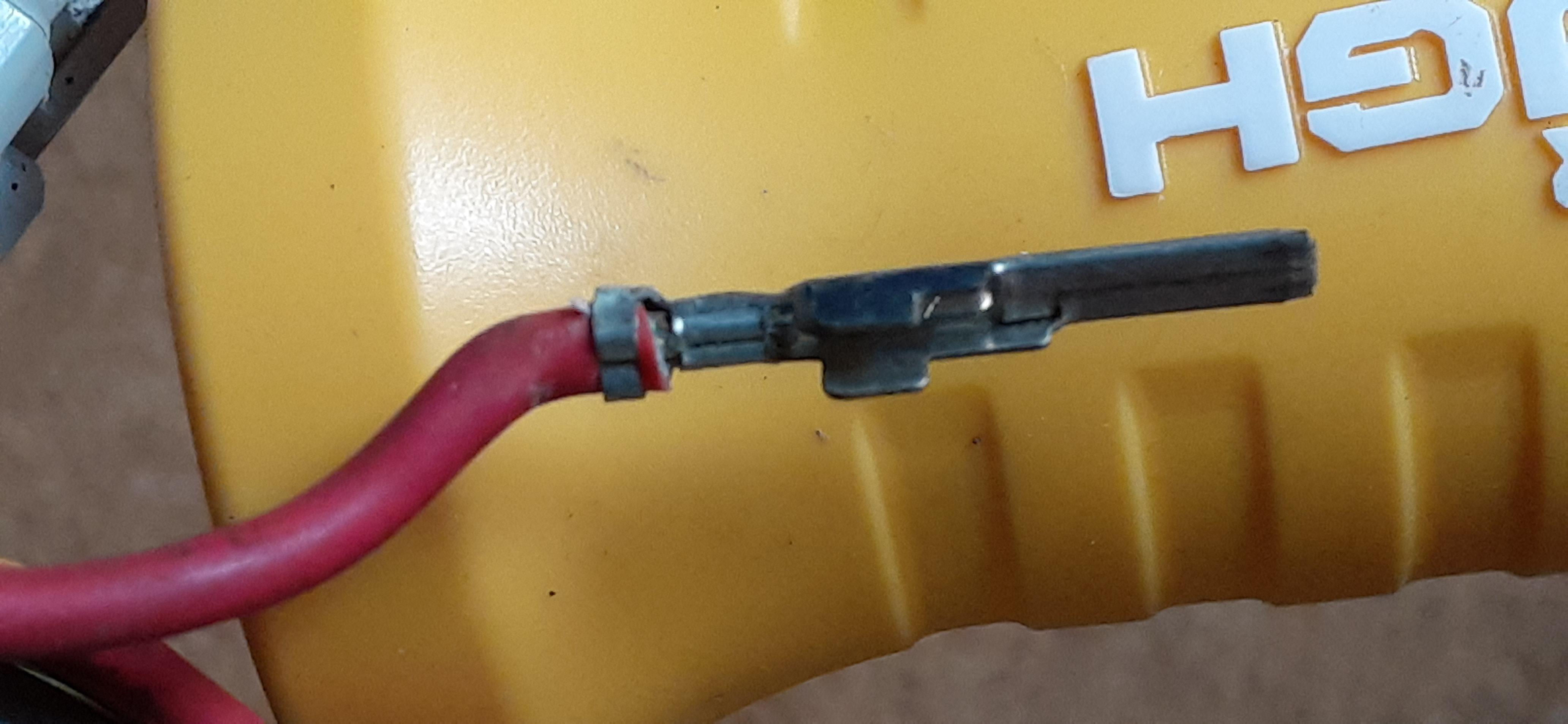
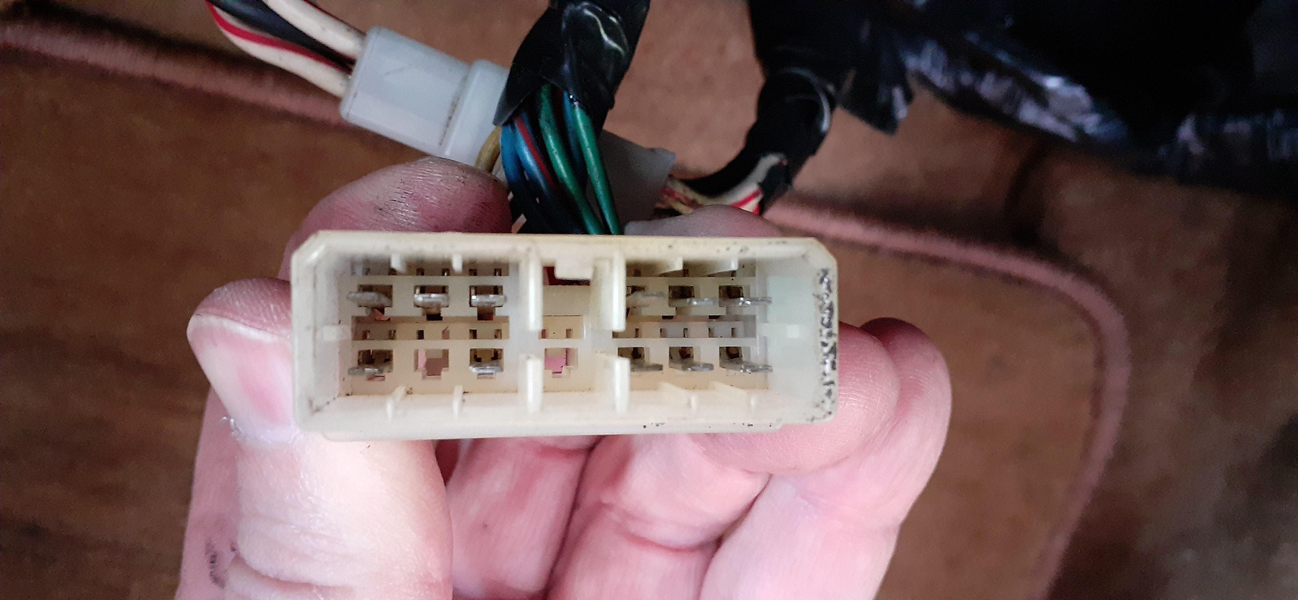
So I was trying to be creative with some wiring for headlight relays in a 78 280Z. When I looked at the terminals in connectors C-2 and C-4, I realized it wasn't going to be so easy. The male terminals are 2.8mm, but they aren't like the typical 2.8mm terminals you find in a 240Z. Between the crimp and the flat area of the terminal, there are side walls. I haven't seen this type terminal before. Does anybody know a name for them? @Captain Obvious?


-
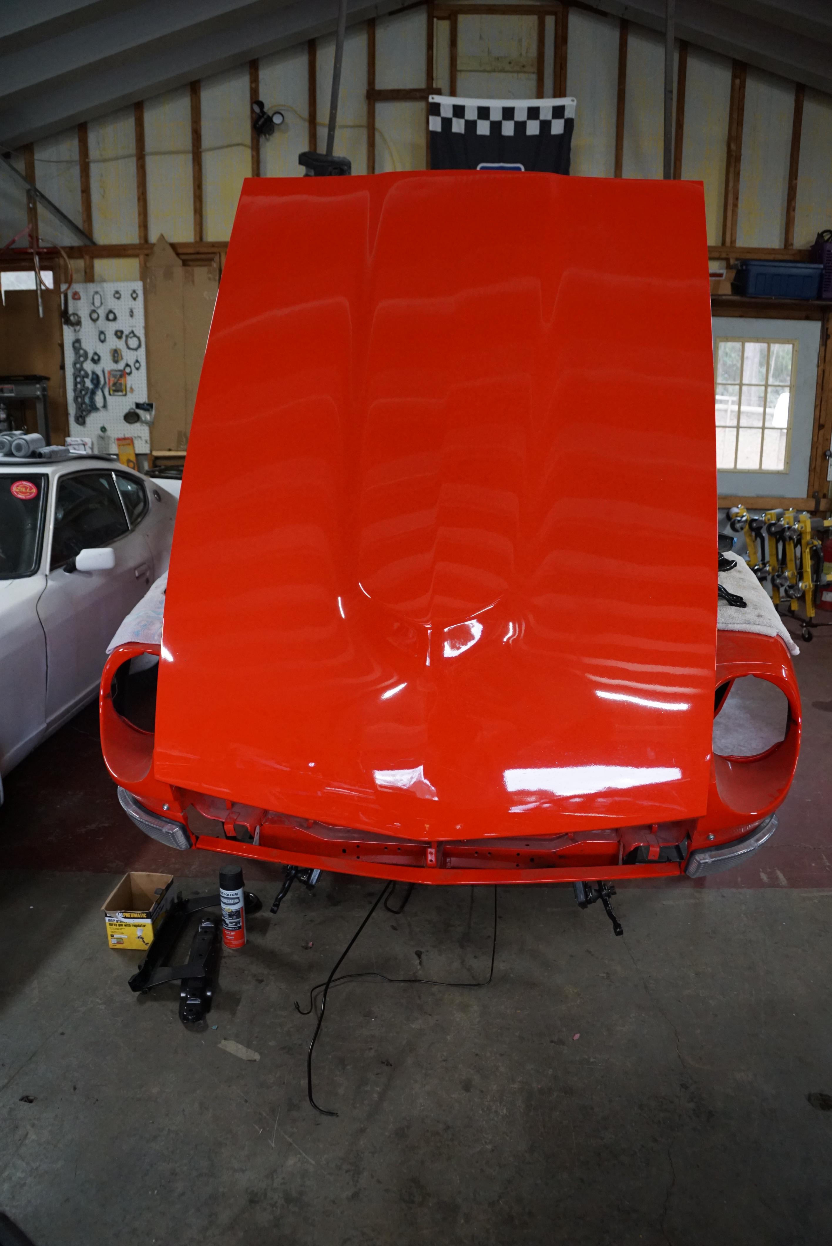
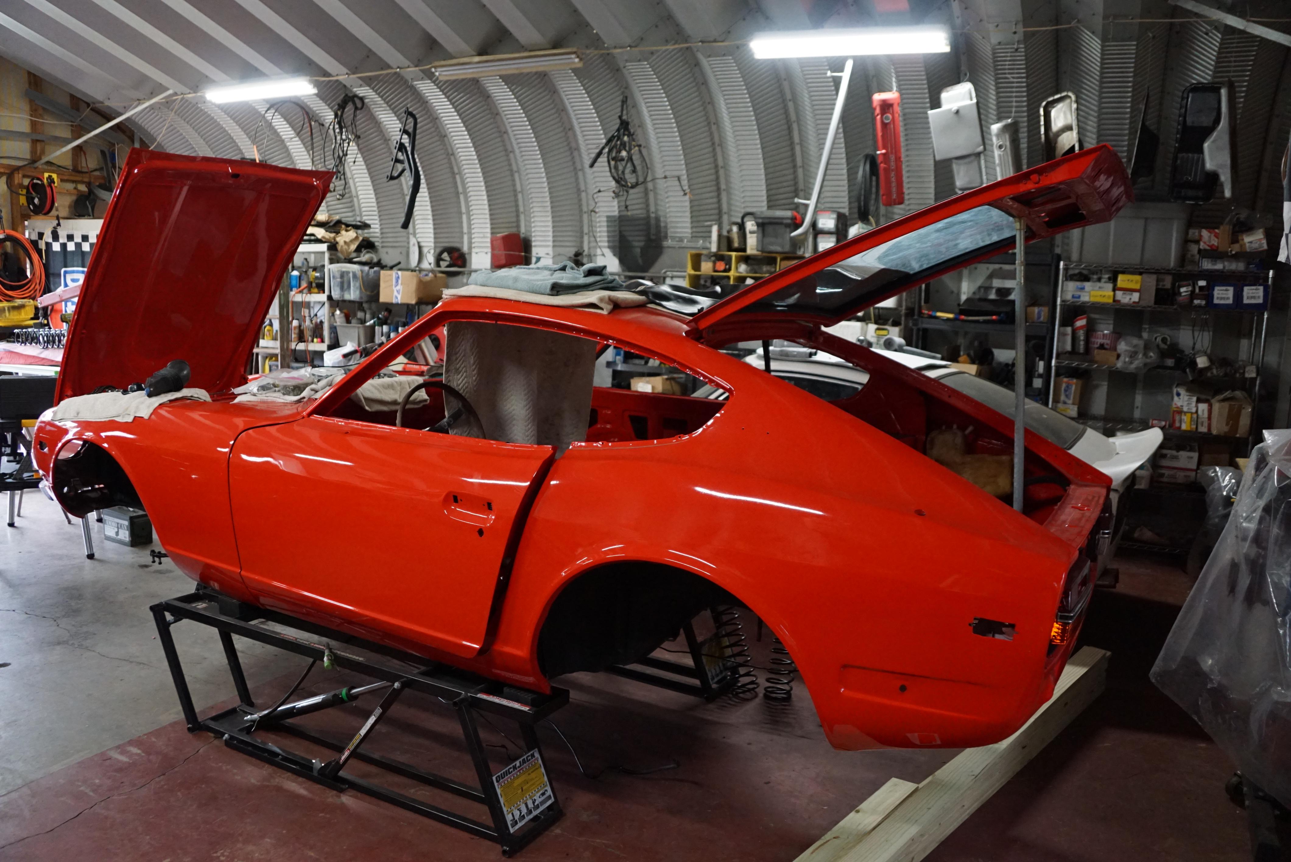
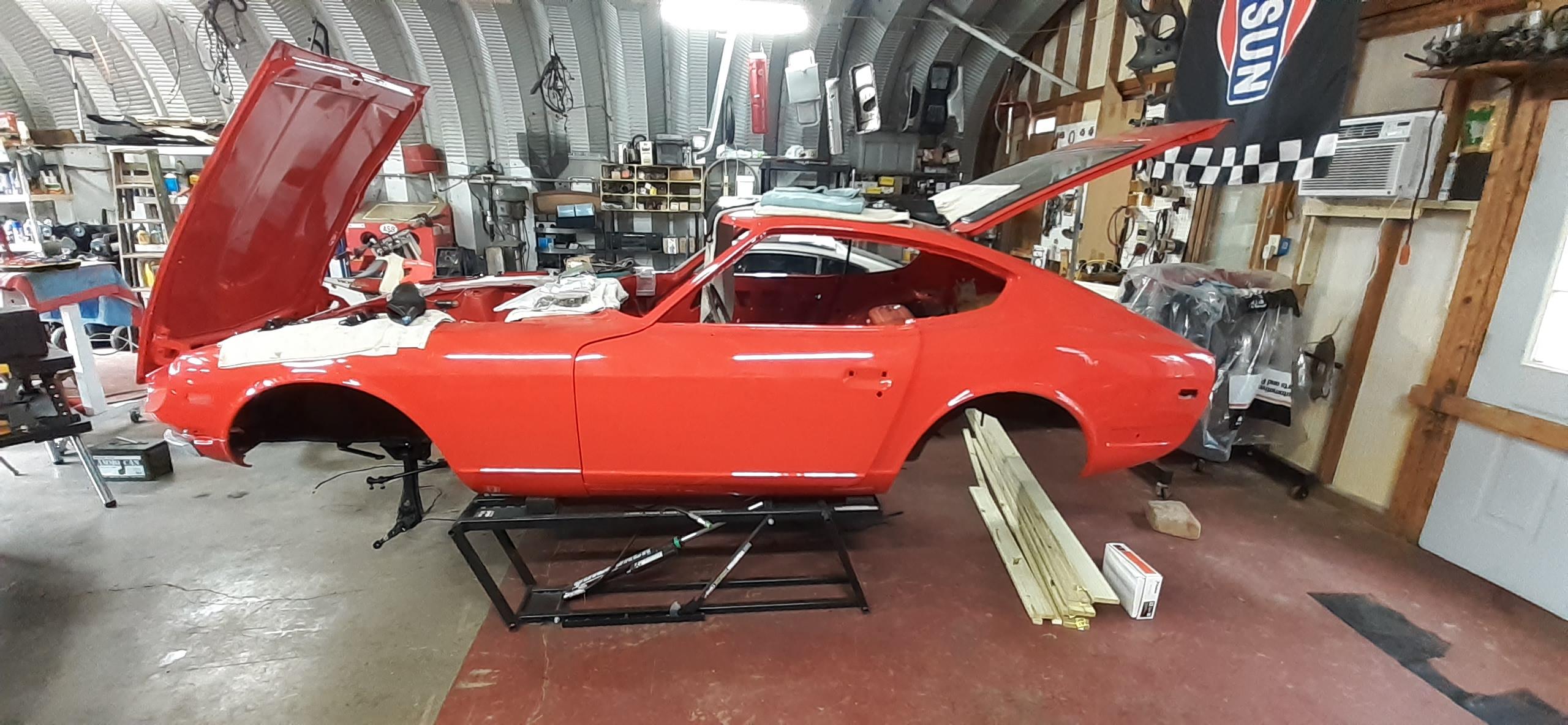
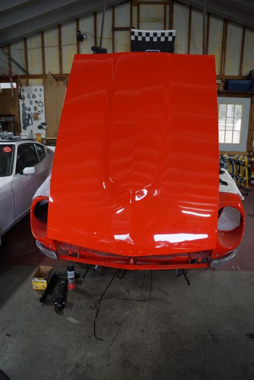
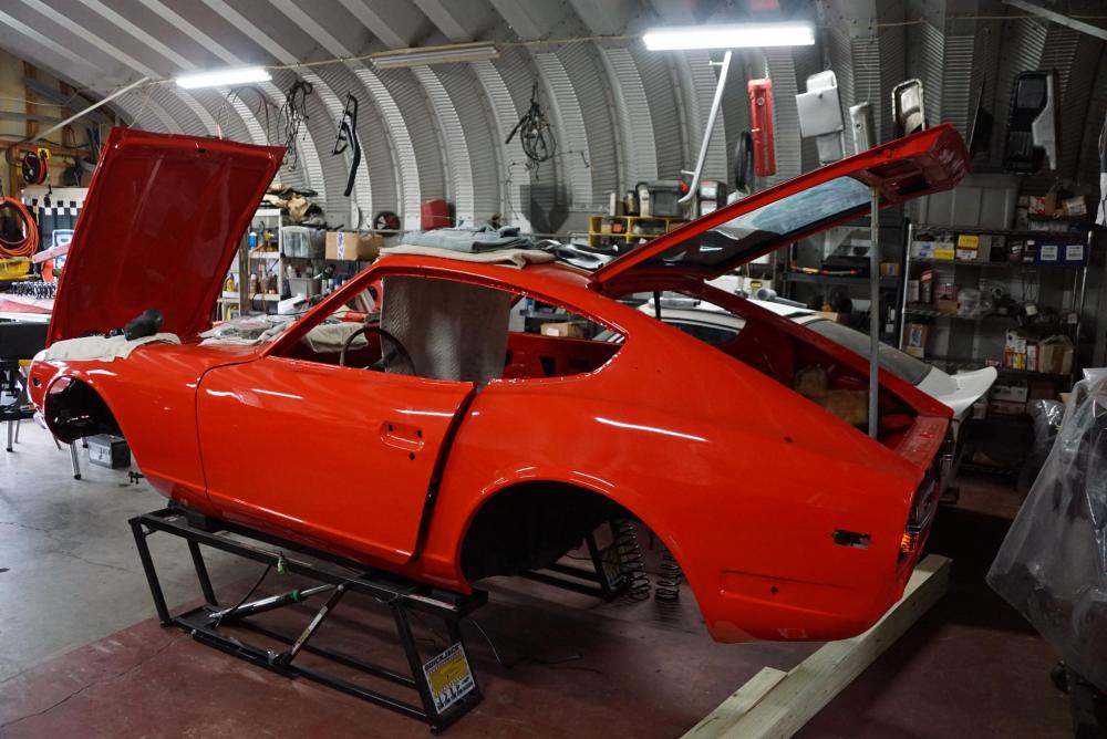
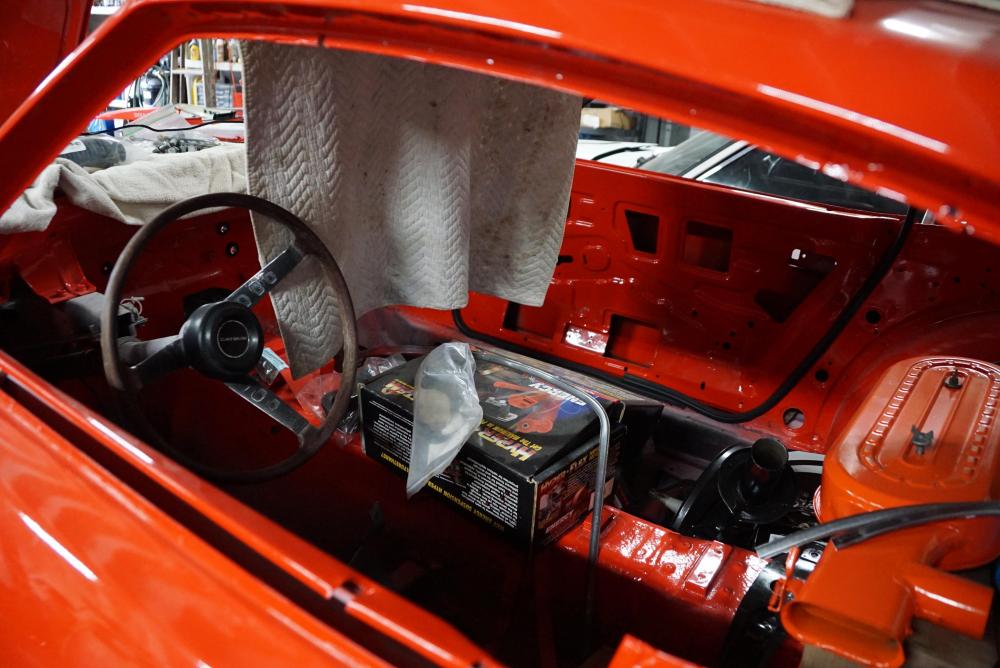
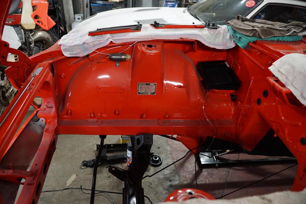
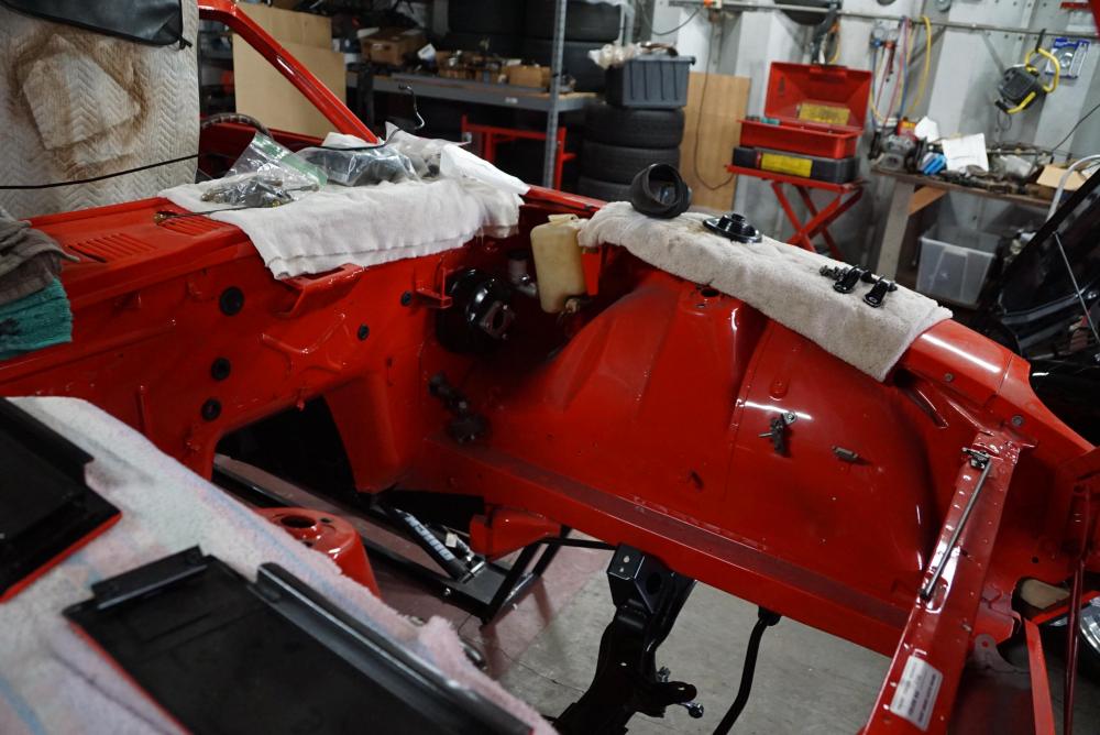
Here are some progress pictures I took today for the restoration of RedWing.

-
Yep, it's in the BAT thread, too. That business OBVIOUSLY does not do drug testing on its employees because whoever is setting the prices on their cars is on crack.
-
They replace the old 2-prong round can flashers that you are used to seeing. No wiring, no fuss, no muss, no stress. You need two. One for the turn signal circuit and one for the hazard light circuit.
-
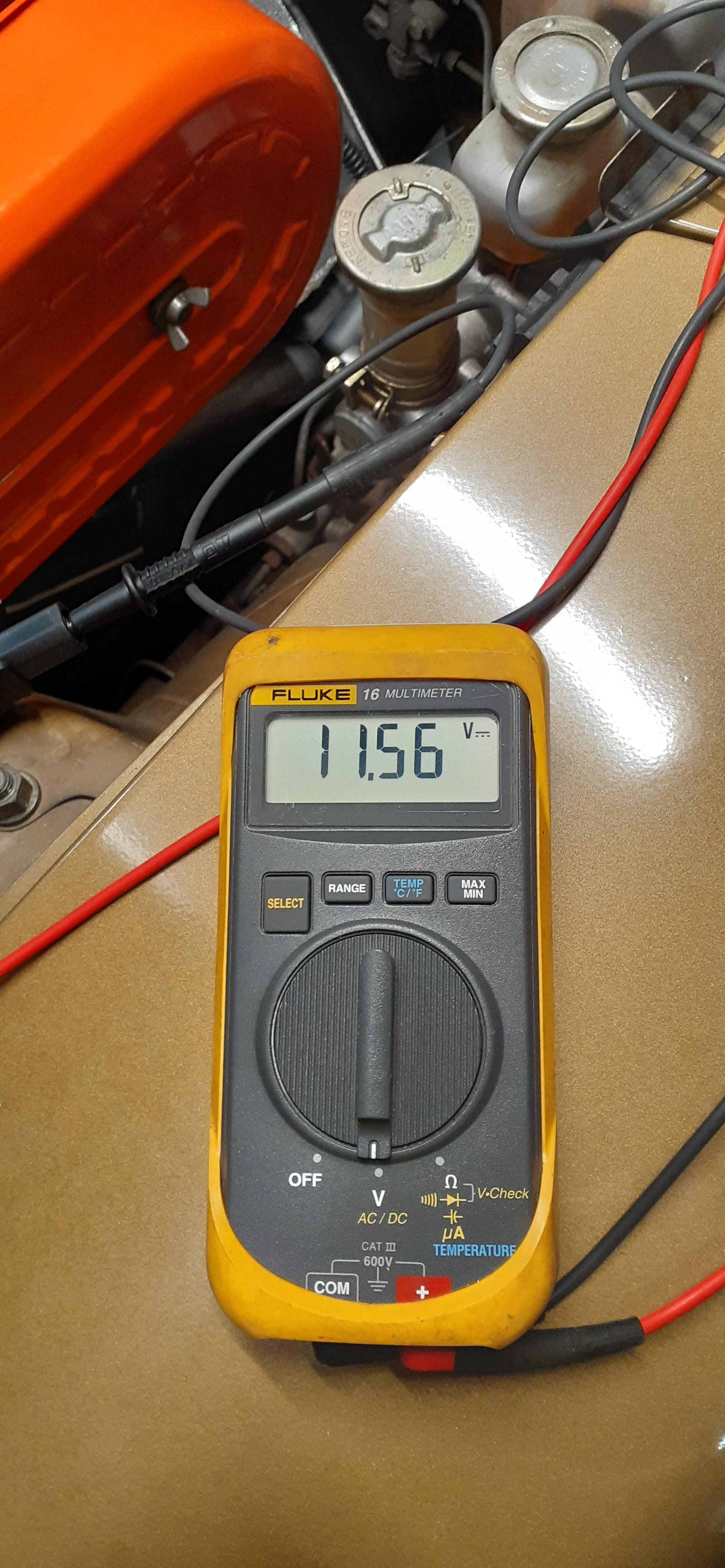
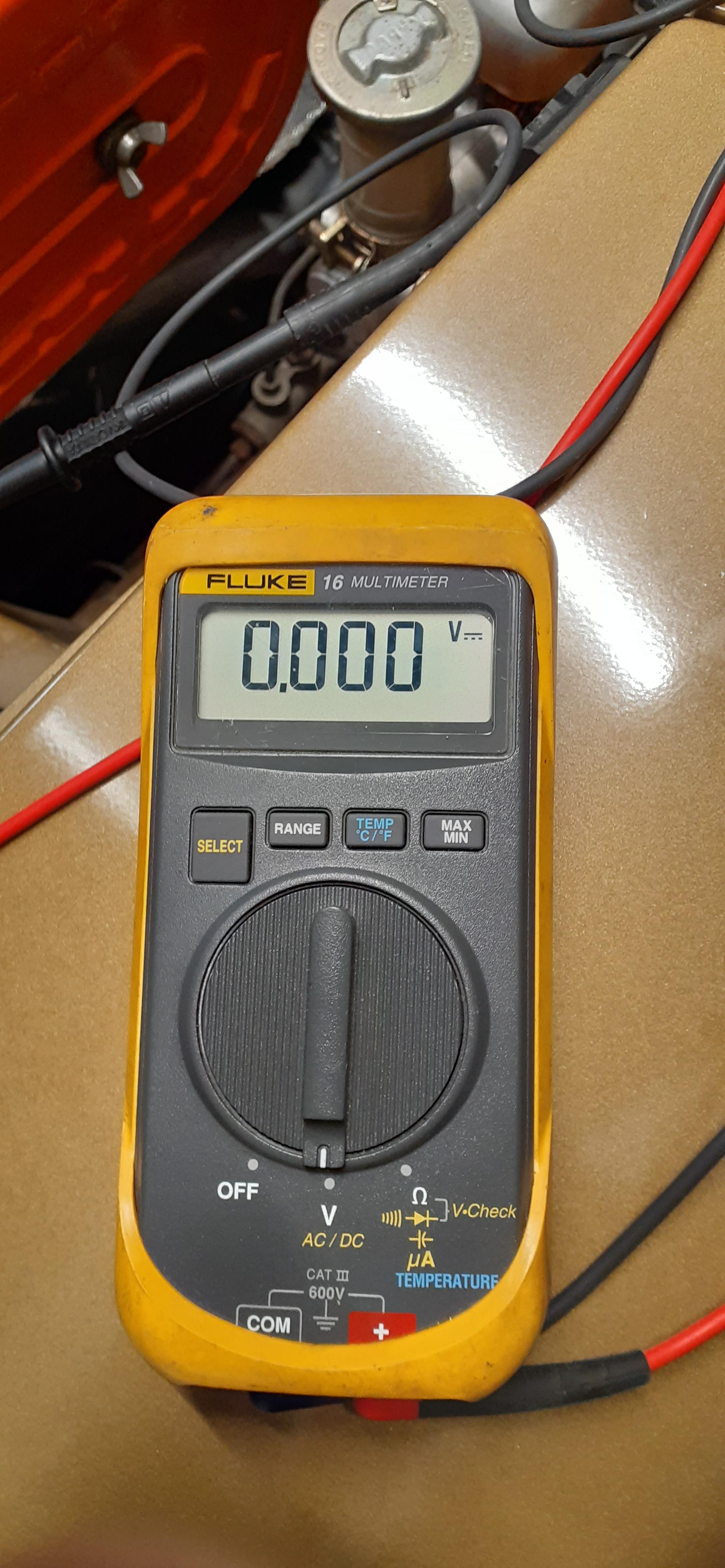
I've had that meter for over 20 years now. It was a Christmas gift from my late mother based on a suggestion from my brother. I tend to use a clamp on ammeter on the car similar to this one: https://www.amazon.com/dp/B00SQ4UETO. It's not precise at all, but it also won't blow up if you have too much current or if you don't have the polarity right. It's great to find a battery drain. Just look on Amazon for test lead kits. The Fluke kits are not cheap, but they are good.
-
So, you have voltage at the coil, though if you are measuring it where I asked, the wiring is not going through the ballast resistor. You need to see if the distributor is triggering the transistor ignition unit (TIU) and if the TIU is working. Download the factory service manual (link in my signature) for the 76, and look at the EE section, starting with page EE-32. That has the diagnostics you need.
-
Um, you still aren't reporting good data. I asked for voltage, and you gave a resistance reading. This is how things should be configured: 1. Connect one lead to coil positive. 2. Connect the other lead to ground (strut tower is good for this). It should look like this all together. 3. Have the meter on voltage. 4. Turn the key on. You should see around 9 volts. I have my ballast resistor jumpered out, so my reading is higher.