


Leaderboard
-

Zed Head
Free Member7Points19,236Posts -
conedodger
Free Member5Points12,513Posts -
Patcon
 Subscriber
 4Points11,142Posts
 -
inline6
Subscriber3Points1,282Posts


Popular Content
Showing content with the highest reputation on 05/17/2024 in all areas
-
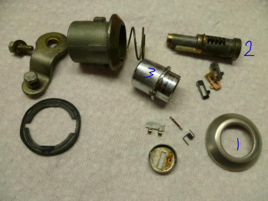
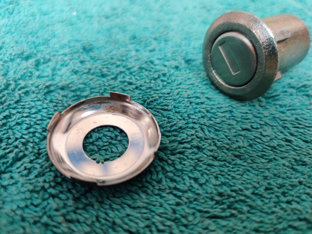
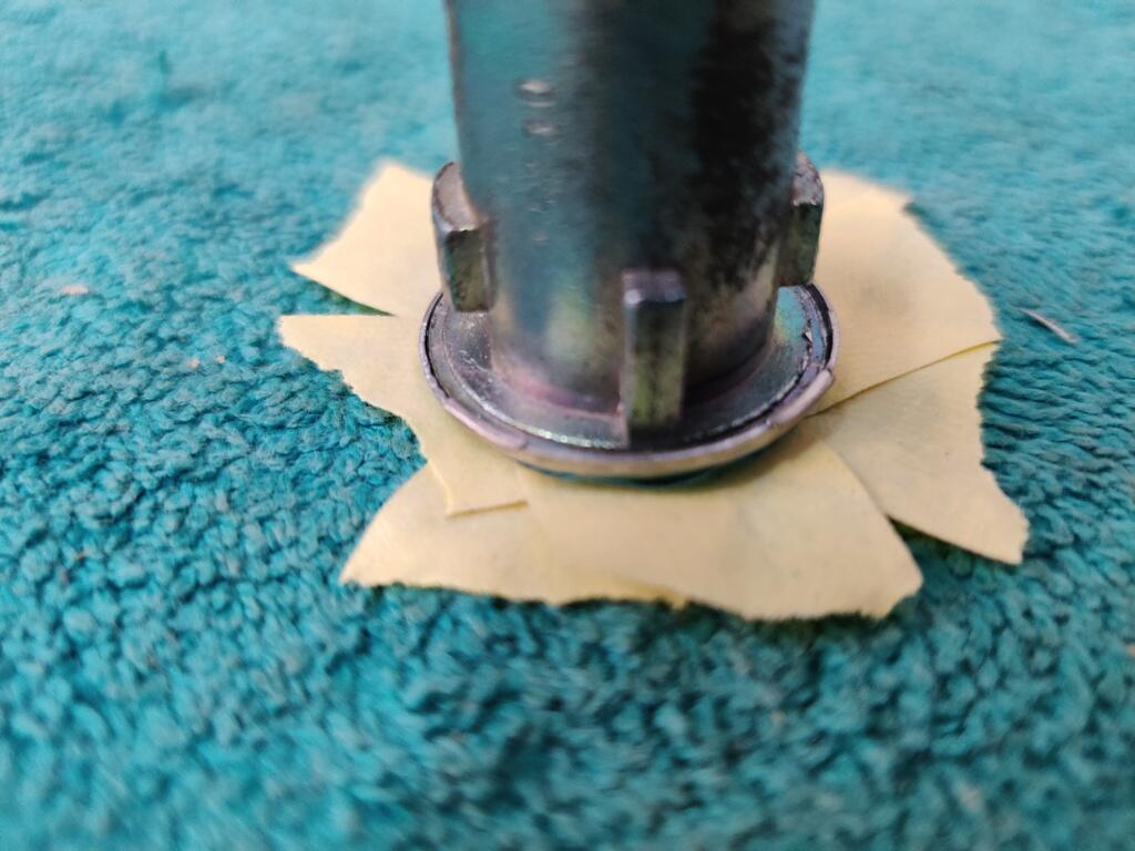
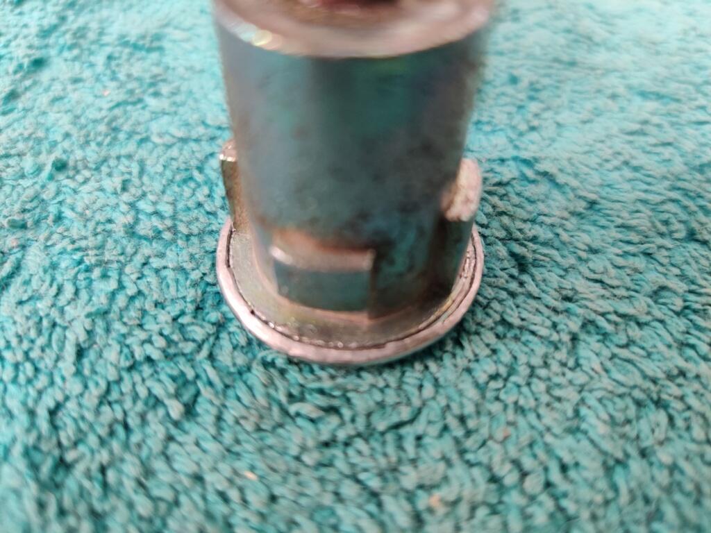
As @Captain Obvious said, the hatch lock is the easiest when compared to the door and ignition locks. To get it apart, you just have to straighten the 3 little tabs on the backside of the stainless trim ring. The trim ring (1) then releases from the lock case, and you can take out the tumbler assembly (2) with the sleeve (3) still on it. To remove the sleeve, you just have to depress one of the "wafers". Then (2) slides out of the sleeve (3). You can then swap out the wafers to match your key. The ignition key and the door locks are more difficult to take apart and put back together. The keying kits I bought off of eBay had replacement stainless steel covers for the door locks. Though this is picture after putting on the replacement cover, you can see here that the cover edge is simply bent around the circumference of the lock case. To get the old ones off, I used an air powered cut off tool with cut off wheel attachment, and simply ground the edge of the existing stainless steel cover (for one half or 180 degrees) of the periphery. I use the flat surface of the disc and not the cutting edge. It is easy. When the stainless cover edge gets really thin, it is easy to pick at the backside fold, and break it away from the case. Then the old cover is easily slid away from the case. With the cover off, as with the hatch lock, you can remove the lock apparatus from the case and change out the wafers. The new covers in my kit.. have these extra tall tab areas (4): They are not needed and would interfere. So, I ground those down with the cut off wheel (again side of wheel - not cutting edge). Then I put several layers of tape to protect the stainless cover surface: Finally, I used a high quality C clamp - clamped into my bench vise, along with a large, thick washer (for backing against the new stainless cover, and a 1/2" drive socket to press the lock tightly against the washer... and used a hammer and flat punch to work the edge of the new stainless cover down around the case flange. I am in the middle of this part of the work to finish up the door locks, and will put finished pics up soon. Maybe with this info, you can convince your locksmith to give it a go?


 3 points
 -
2 points
-
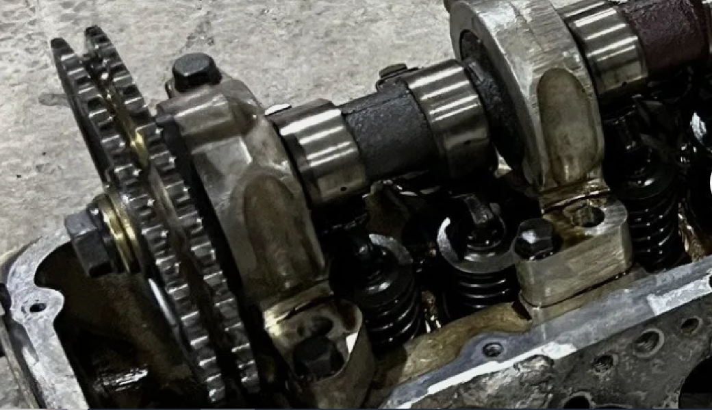
2 pointsHere's an old thread with good stuff in it. Excellent picture of lobes-up by Cliff/unseen. Just realized that I have no memory of the ignition timing mark on the damper pulley ever being mentioned by Mr. Vancouver. That's the other indicator of TDC. Get the cam lobes up, rotate the engine until the timing mark is at zero. The adventure is in trouble if TDC compression cannot be found with this information.2 points
-
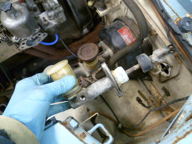
My little eye spies the wrong clutch master cylinder. It's a Nabco, but it's the new style. You guys are all gonna regret me seeing an early car with my own two eyes. Hahaha!! You need one of these. Maybe not quite as crusty, but this style:
 2 points
 -
2.83" long outside to outside .05" diameter2 points
-
1 pointThis like the Adam Sandler movie "50 First Dates". Each day is like the one before never occurred. You have one of the three. Do the other two. Side note - I finally discovered how to do a multiquote from multiple pages.1 point
-
1 point
-
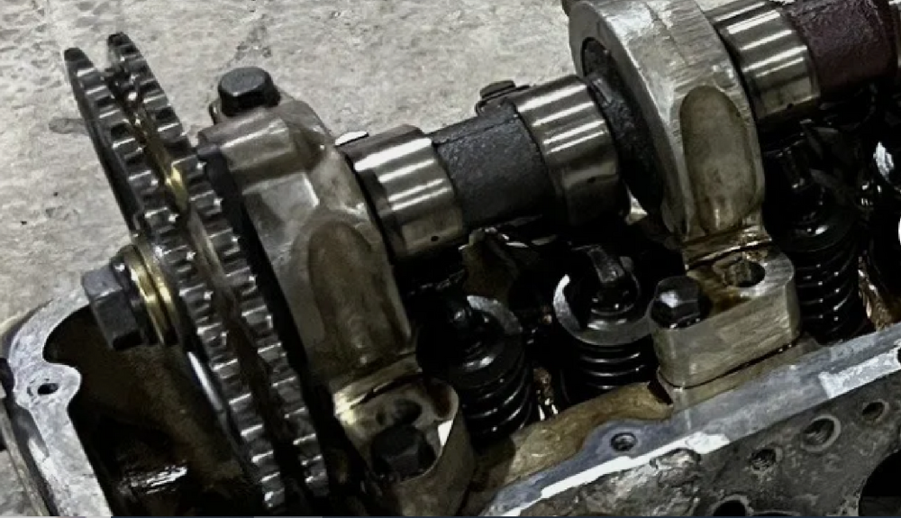
1 pointYou're right. I thought the other lobe might not be visible behind the timing sprocket but lost track of the actual configuration, even though I had pasted the rusty cam picture earlier. I dug up an eBay picture for reference just now, pasted below. He wore me down, I should have checked. Not sure how two cam lobes sticking up can be misinterpreted. Still, all of the advice given by everybody in all of the numerous posts is good. He just needs to get some of it done. The picture below shows the #1 cam lobes. The piston is not at TDC on compression stroke.
 1 point
 -
1 point
-
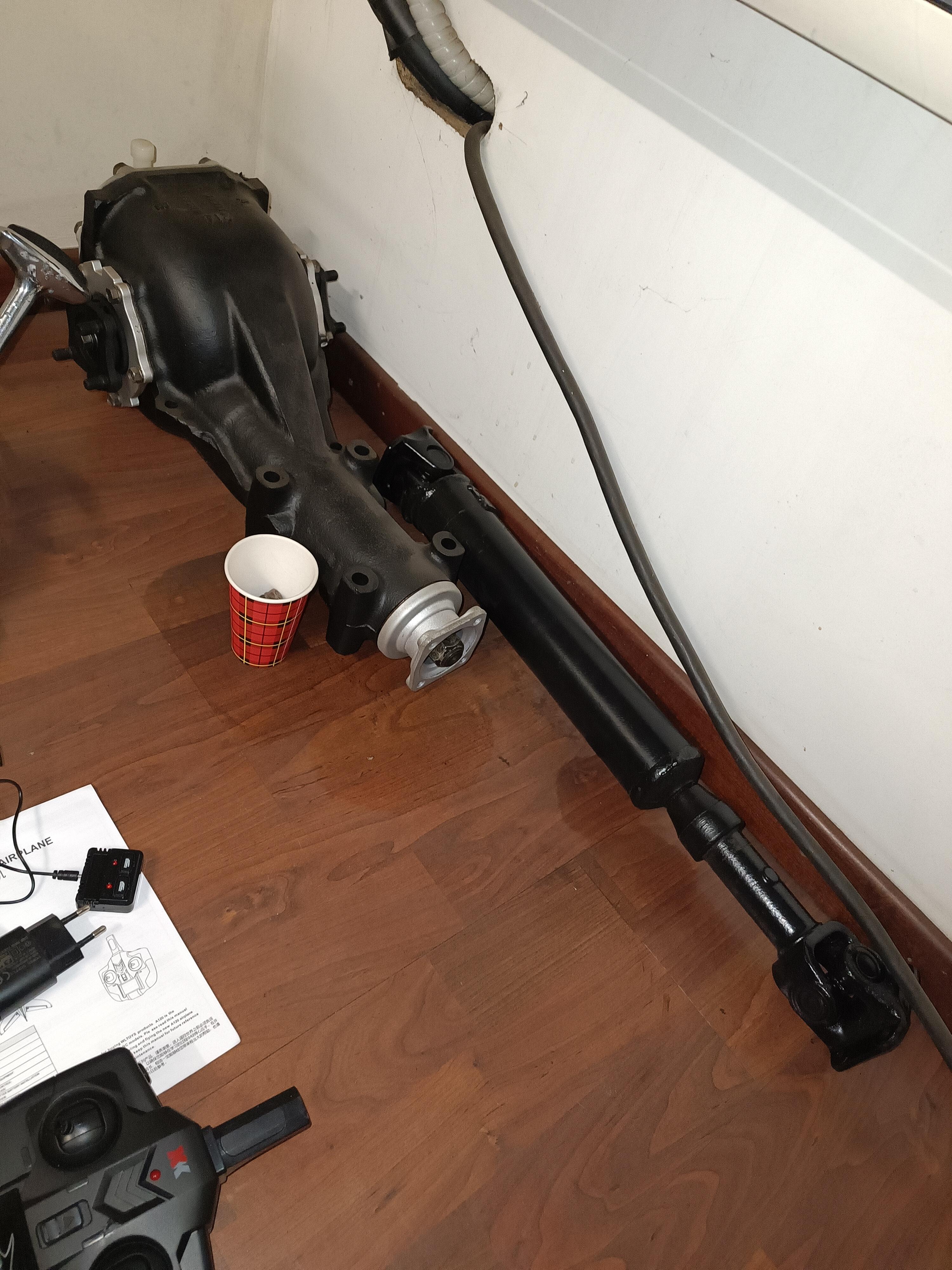
1 pointVery likely to be from an original European market variant pairing, yes? Have you got the correct double-flanged sliding-joint propeller shaft to join the two together?1 point
-
Many thanks ! Closest I could find is ..047x2.76", .39 OD. I'll give that a try1 point
-
1 pointI may be missing something but both cam lobes on #1 don't appear to be up in that picture...1 point
-
1 point
-
How did you determine 'top'... Was it the inertial* top? Or was it the geometric** top? * 'Inertial top' = the point where a carpenter's level would rest if levelled and placed on top of the tower circle. 'Inertial' is the same as 'plumb'. ** 'Geometric top' = the point where, when viewed from the front of the engine, a line drawn perpendicular to the top face of the engine block (head gasket surface) and going through the camshaft centre intersects the top of the tower circle. If you use the inertial top to gauge TDC with the cam lobes, you'll be off by 12 degrees. If you use the geometric top, you'll be ok. For an inline engine with normal architecture, all of the relationships between moving parts are based on an X-Y axis going through the centre of the crankshaft, where the Y axis drawn along the centreline of the cylinder bores (plumb 'vertical') and the X axis is perpendicular to the Y-axis (plumb 'horizontal'). When an inline engine is mounted in the vehicle with no cant angle, the X axis runs parallel to inertial/plumb horizontal and the Y axis runs parallel to inertial/plumb vertical. Picturing or calculating where all the parts sit when Cyl. 1 is at TDC is easy. When the engine is canted to one side, picturing or calculating where all the parts sit remains easy if you also cant the X-Y axis by a matching number of degrees. Having done so, the X-Y axis becomes an X'-Y' axis, and is 'relative' rather than 'inertial'. In other words, you have to adjust your frame of reference so that it's canted, or rotated, by the same amount as the engine block. If, on the other hand, you try keep your frame of reference aligned with 'plumb', things get messy. EZ-to-understand example of how this plays out: You're reassembling your L24 engine on an engine stand and have the engine rotated on the stand so that the cylinder bores are plumb vertical. You find TDC for Cyl 1 by rotating the crankshaft until the piston is at the top of its travel and the two cam lobes are pointed up.1 point
-
Like i did.. DON'T forget to shoot some ( A LOT!! of) pictures (In different angles!) how it go's together because when it's off you don't have a clue how it shoud go together.. Old.. New.. On the engine.
 1 point
 -
1 point
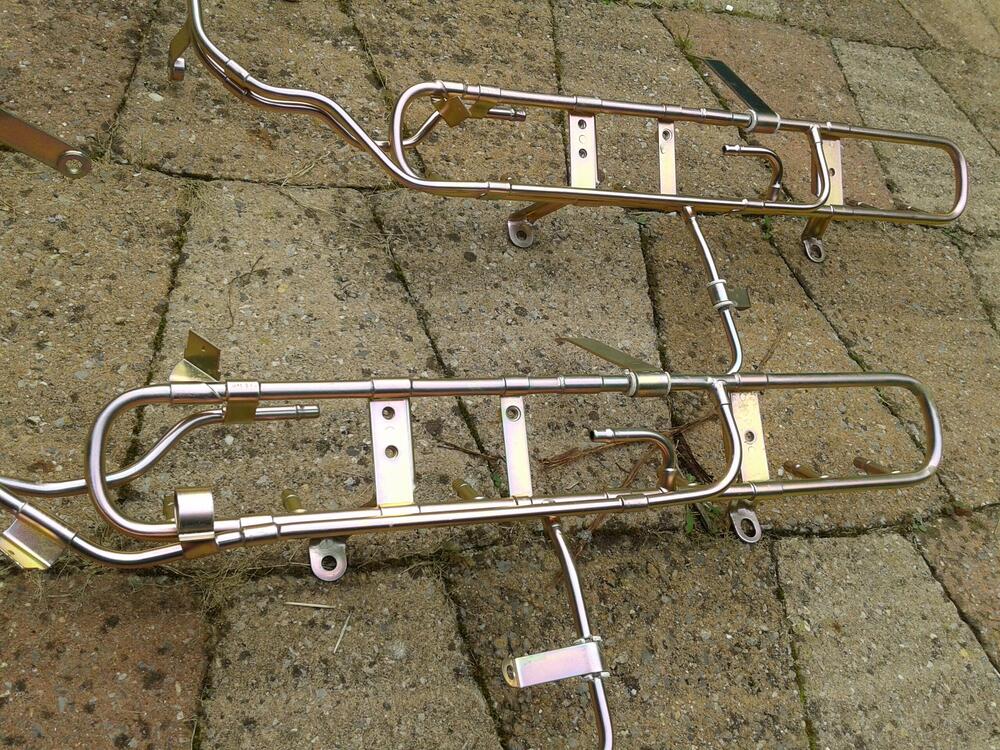
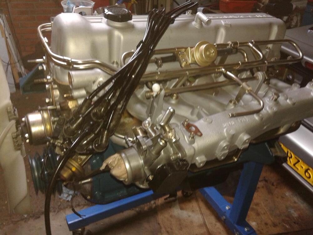
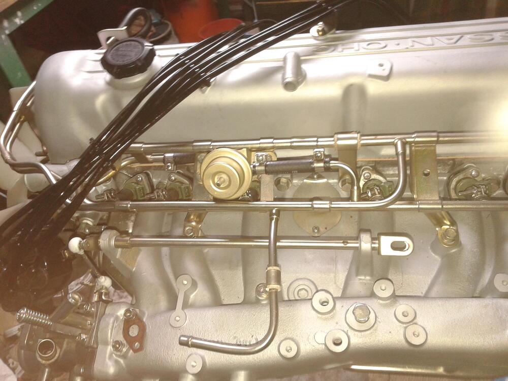
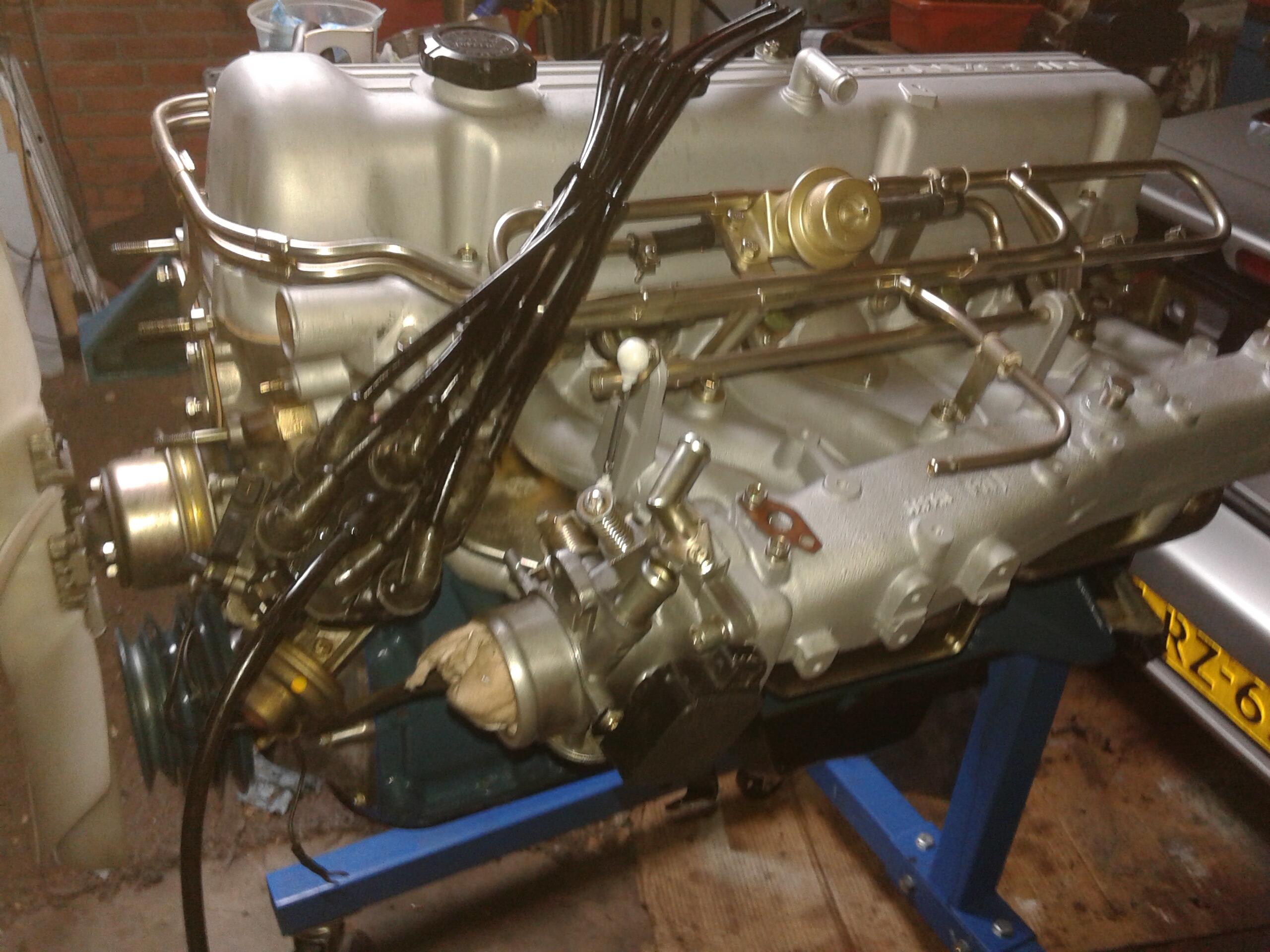
 I know a few people were following along on this- been a while since I last posted here- but finally all came together! Mounted up and running strong! Still a few details to work out; but runs good, sounds good, feels good on the initial pulls. Super happy it worked out!1 pointThanks. In the absence of any other information, I had taken some measurements from a drawing that appears in the 1970 FSM (see below) and came up with 11.9 degrees... so I was close. Good to have this confirmation.
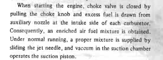
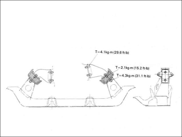 1 point1 pointFor where you're at right now I would do the above. Whenever you try to start the engine and nothing happens you suck raw fuel in to the cylinders. Do the above, pull a spark plug and make sure it's not soaked with gasoline, then try to start it with starting fluid if the plugs are dry. When you spray the fluid in to the carburetors make sure the carbs are open so that the starting fluid can get in to the intake manifolds and cylinders. Also consider the choke.
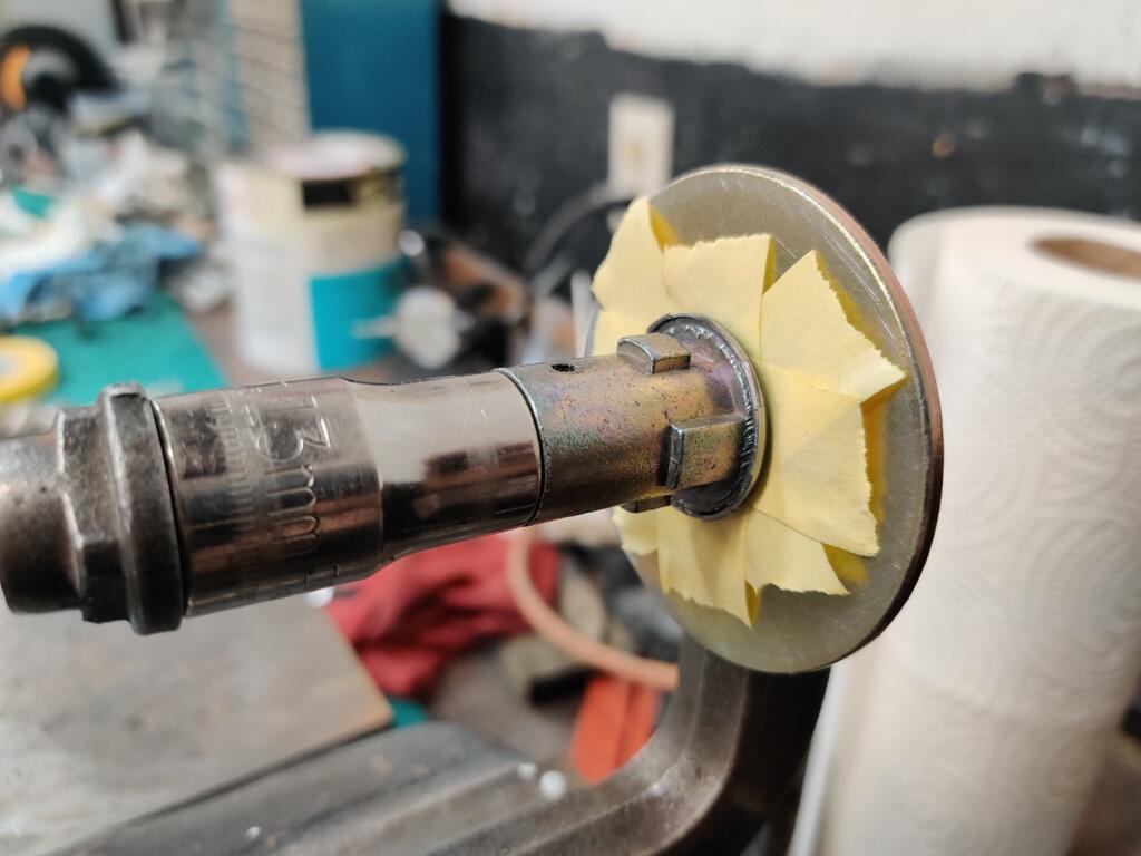
 1 pointYes had a little break, which was needed. My zx is down at the moment, all the injectors failed so i need to replace them, i have the new injectors just need the time to install, plus i want to replate the fuel rail and a few bits in the engine bay to tidy things up.1 pointHaha its been a while but yes the dream is still alive. albeit a more expensive dream by the day...1 pointIf the metal gets too hot or overworked, it expands and becomes wavy. Basically ruined1 pointIt always makes me smile when taking off suspension peices that show the yellow Q/C brush marks…..
 1 pointFactory-fitted air conditioning was available from the beginning of production in the Japanese market. The core support panel was shared between Domestic and Export markets, hence the mounting holes for the S20-specific air cleaner box and radiator overflow bottle being present on Export cars.1 pointAnother Datsun GTO. 240Z this time. No reserve! https://bringatrailer.com/listing/1962-ferrari-250-gto-replica/
 1 pointAnother decent driver. 1976 was a good year. Federal model in North Carolina. https://bringatrailer.com/listing/1976-datsun-280z-85/
 1 point0 pointsThanks all, Confirmed blown head gasket over multiple cylinders. All piston tops steam cleaned on the intake side of the head. First pic is piston #6 how the piston top should look on a high mileage engine, covered in carbon deposits. Second pic is piston #3 nice and clean with drops of coolant on top. #3 was also the lowest compression reading at 150 PSI. It gets worst #4 and #2 have small portion of the piston top cleaned as well, all on the intake side. So the entire center section of the gasket failed. Confusing how all the test I ran where negative to coolant in the oil, carbon dioxide in the coolant. So where did the milky foam go? In my catch can venting the valve cover and block, the dreaded milky foam was present when I opened the valve :(. The engine starts and runs fine, not smoking???????????? Open the wallet and rebuild.
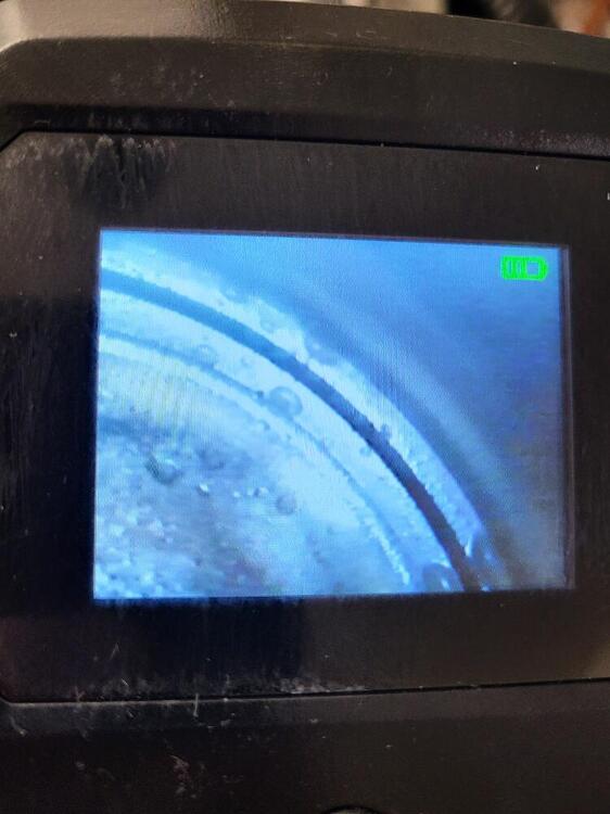
 0 points


Important Information
By using this site, you agree to our Privacy Policy and Guidelines. We have placed cookies on your device to help make this website better. You can adjust your cookie settings, otherwise we'll assume you're okay to continue.