Leaderboard
-
HS30-H
Free Member5Points5,509Posts -
240ZBUILTBYME
Free Member3Points237Posts -
dspillman
 Subscriber
 3Points445Posts
 -
kats
Free Member3Points2,215Posts
Popular Content
Showing content with the highest reputation on 03/24/2023 in all areas
-
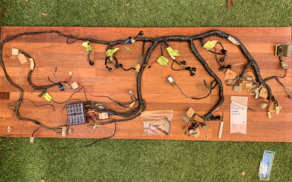
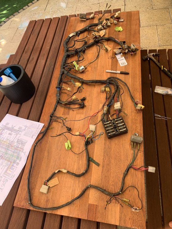
My z guy Martin is giving me the hurry up to get my dash harness to him so he can install my gauges, I wanted to do an overhaul on all the terminals and plugs, so I first created a nail board and splayed out the harness. I then started studying the wiring diagram which to be honest at first look overwhelmed me, but once you have the harness splayed out and diagram in front of you it gets clearer. Then I marked out all the harness intersections on the board and began labelling each terminal using the wiring diagram to help me identify terminals or plugs that weren't connected to anything when i removed it from the car. Next I plan to strip the tape off the harness putting small bands of temporary tape to hold its shape and intersections, then Ill inspect and repair the wires, once I'm happy with the wires i will start depinning, replacing pins and plugs. before retaping I'm going to see if i can get it continuity tested or if i can do it myself.
 3 points
 -
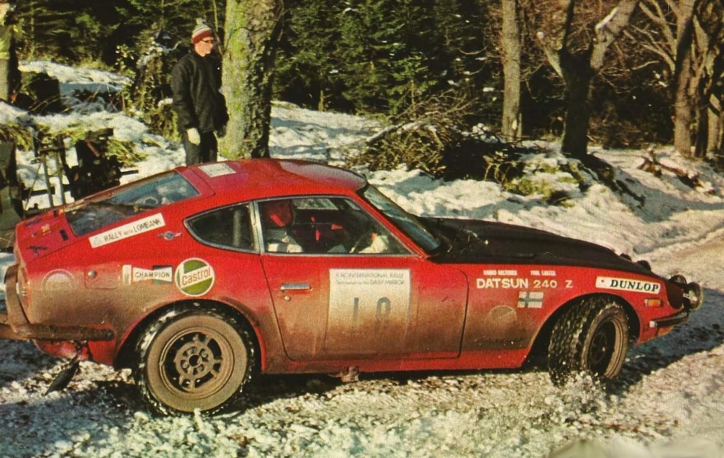
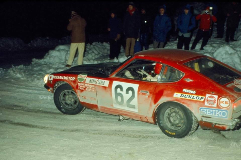
Great 'behind-the-scenes' photos there Kats. I have not seen those before. Excellent! Yes! Rauno Aaltonen was often seen wearing a red crash helmet around that time. In later years I have seen photos of him using a white one too. Aaltonen had a reputation for being fastidious and meticulous about his preparation, and whenever I see photos of him before rallies and at servicing that does seem to come across. He liked to put a '12 O'Clock' stripe on his steering wheels and he also preferred the blue WILLANS brand safety belts, which he would swap with the factory Works team's Takata belts. Here are a couple of colour shots from the '70 RAC and '71 Monte:

 2 points
 -
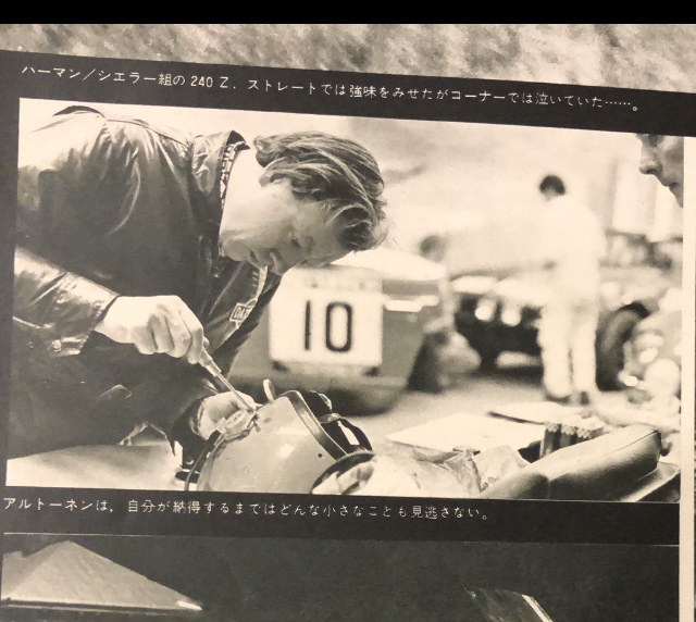
Nice pictures Alan, thank you so much for sharing. I add this from a magazine, I see a red helmet on the table, is that for Aaltonen? Kats

 2 points
 -
2 pointsNo worries. If the OEM setup was mono, then using it would not provide stereo, and may also lead to the premature failure of the speakers. I strongly suggest you get some speaker wire and run dedicated right and left circuits to the speakers.2 points
-
2 pointsSince you're going down that path... Most non-industrial facilities in the US are bringing in 208VAC (two phases off a WYE transformer). At the entry point for the facility (service entrance), there is a neutral (return path) bonded to ground. That is put in the circuit with one of the legs of the 208VAC to provide 120VAC. In Canada, instead of using 480VAC as low voltage, they use 600VAC. The fun part is to source parts in North America for equipment to ship to a 50Hz country since almost everybody in North America publishes specifications for 60Hz. The most fun was a project where all of the equipment downstream operated at 60Hz. The generators operated at 60Hz, and it was being installed in Europe. They had to place equipment in between the utility and our equipment to go from 50 to 60Hz. Ships have to deal with this, too. For instance, the US Navy ships are designed to support voltage and frequency used in America. When they get shore power while docked in foreign ports, they have to have the frequency converters between the shore and ship. Going back to @chaseincats (to pretend that this rambling is still a little on topic), as @Racer X explicitly said, match impedance between the stereo and speakers. Mismatched impedance will work, but not as well.2 points
-
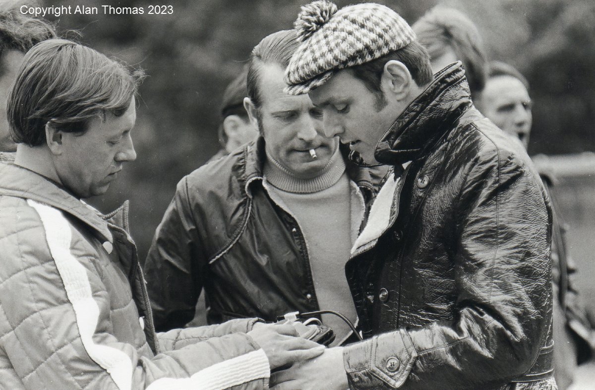
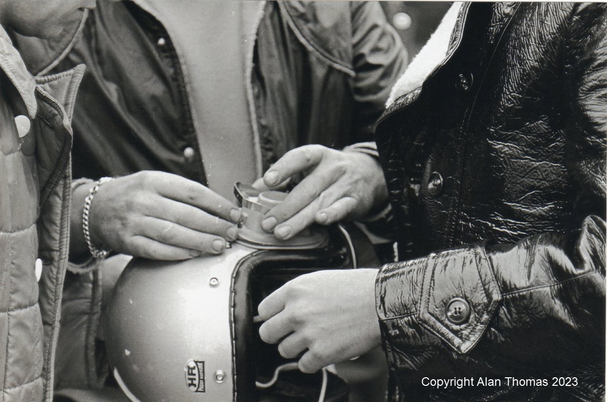
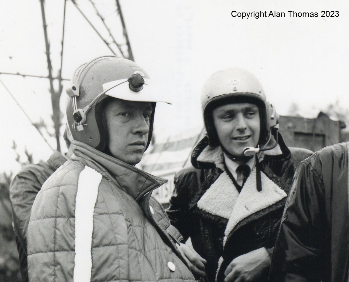
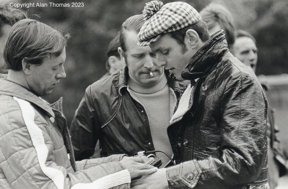
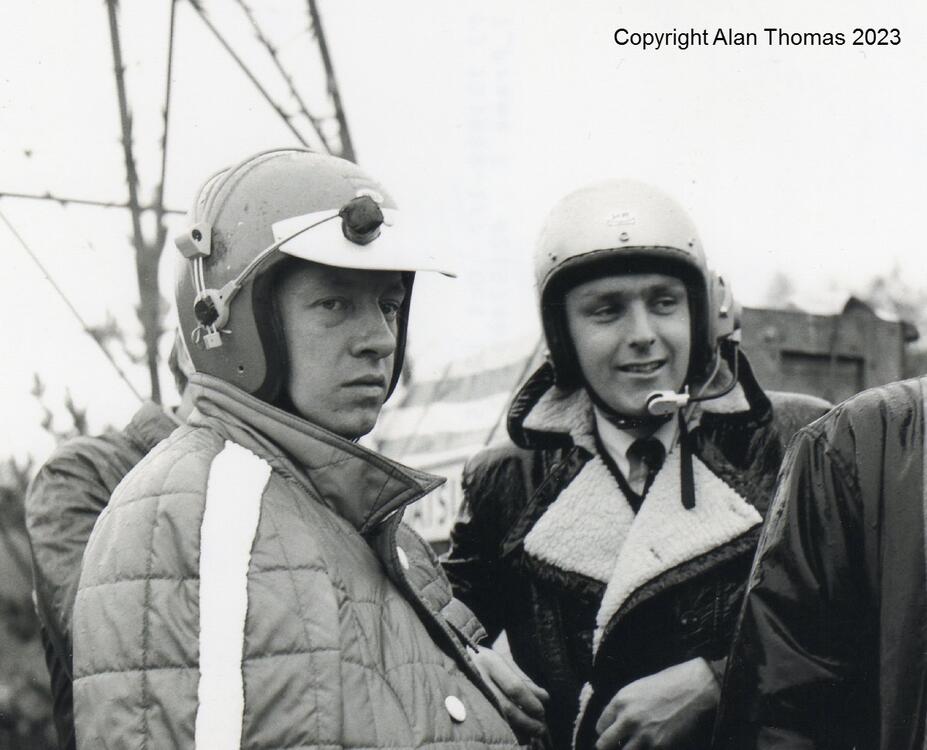
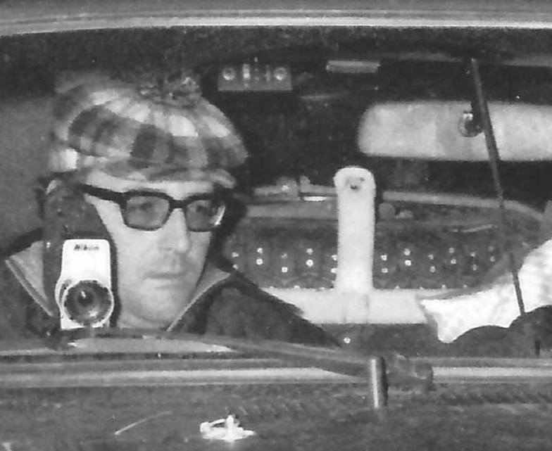
Nissan's Works team called this system an 'Interphone' (the period English vernacular being 'Intercom') and they had already been using similar systems on previous Works rally cars. They were especially important/useful on the East African Safari Rally with its long and arduous road sections between special stages, where it was still necessary for the navigator to call the route to the driver, often at fairly high speeds (high noise). They would have been necessary on 'recce'/reconnaisance practice and ice note runs where the crew needed good communication to make accurate pace notes on events such as the Monte and RAC rallies. For the 1970 RAC Rally, the crews were using single-ear interphones that could be used also be used over specially-adapted Paddy Hopkirk crash helmets. Kind of unwieldy, and it is easy to see why the next step was to integrate the earphone on the inside of the helmet. Some photos of testing in the UK prior to the 1970 RAC Rally, where the crews were getting used to the new systems: Rauno Aaltonen, Hans Schuller and Tony Fall: Detail: Aaltonen and Fall: Tony Fall with Works team mechanics, team manager Takashi 'Waka' Wakabayashi on the left:

 2 points
 -
Just figured it was time for clean thread on this. I used a NTK25572 single wire O2 sensor for the ECU AEM wide band gauge and sensor for the read out Stock ECU, PRW-2 for the ignition transistor (and the correct transistor as well for testing). Aftermarket CAS (NTK) due to OE flaking out. the rest is all stock (turbo/CHTS/Knock sensor, Idle air control (vacuum modulator to control it), EGR.1 point
-
Beautiful pictures Alan! ”Aaltonen, he never overlooks every tiny detail. He keeps on doing it until he is satisfied” That is what the text is saying about Aaltonen working on his helmet. Kats1 point
-
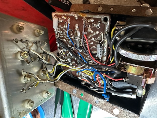
Picture One: Fog Lamp wiring - Red - taped off = correct. The engine bay harness has corresponding wires also taped off near the horn wiring R & L sides. You are also correct about the 6-pin connector with the greens - hazard switch - which looks bypassed by the factory. Picture Two: Top connector (blues) is the stock power antenna (which operates differently than the more modern auto antennas) Middle connector - The two whites are for the speaker. The blue I don't remember, but I think it may be power to the radio...1 point
-
1 pointI was able to find the model number - the head unit is a Pioneer DEH-6300UB1 point
-
1 point
-
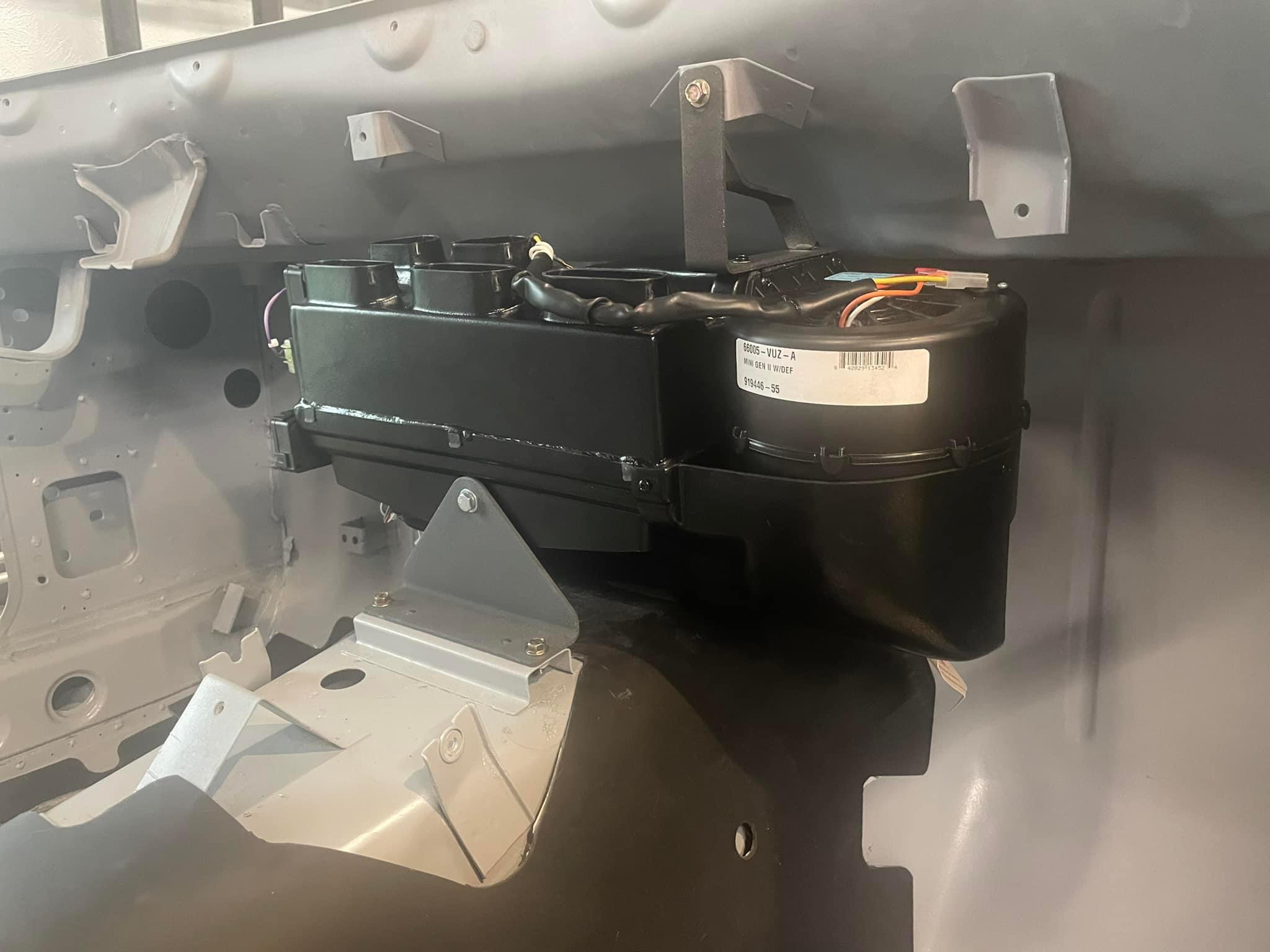
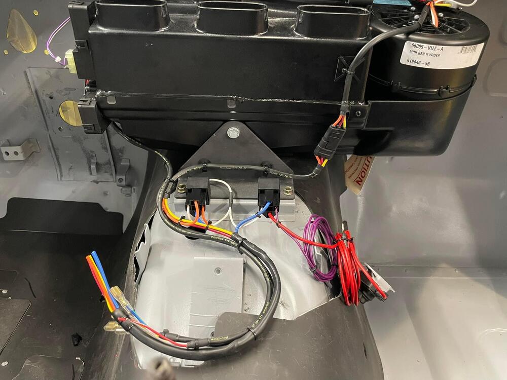
1 pointInstalled the Vintage Air Gen II Mini and made some progress on the wiring. For anyone who’s installed these, the harness that comes with the unit is long and bulky. Ended up pulling most of it off and tailoring it better for the Z.
 1 point
 -
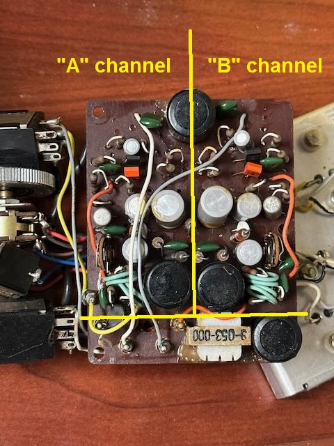
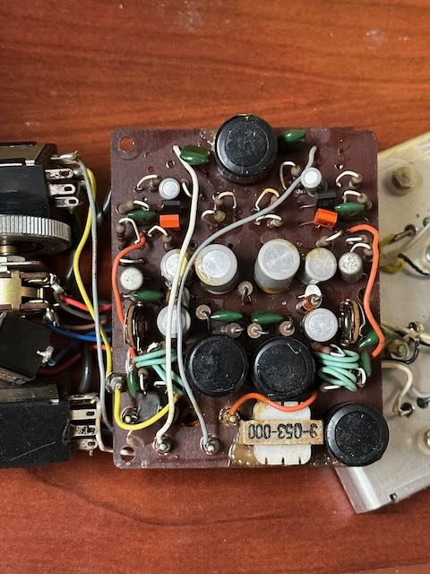
That board is mostly symmetric about the middle. Undoubtedly the two independent channels. It'll save you quite a bit of time with the reverse engineering because you only have to do half. This is what I mean: I would guess that the few components at the bottom of the pic that are not symmetric (the coil and the big cap) are most likely input power filtering, and the big cap at the top is most likely a power supply filter as well. The big ring of solder trace around the board perimeter is ground and the big strip running down the middle is most likely the high side of the supply.
 1 point
 -
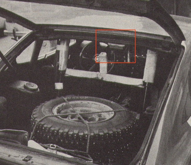
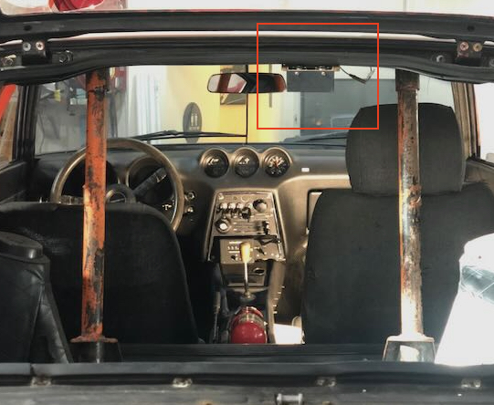
For the 1971 Monte Carlo, the Works team appeared to employ (from what information I can gather) what is basically a 2-channel power amp with gain control to facilitate communication between driver and navigator. The essentially muffler-less cars were already loud to begin with (by all accounts), and subtracting any sound deadening, plus the incessant constant rattling of two in-cabin fuel pumps, one could imagine the occupants would be losing their voices around day 2. Interestingly, I have a fair number of period photos where the team did not appear to be wearing headsets while underway, so perhaps the system didn't provide the expected benefit, apart from when the occupants donned helmets. I believe mine to be original hardware, as I have a detailed picture of it installed in the car from the 71 Monte Carlo (last picture below), and another from October 1971. It is a very compact 12V device, made by Teikoku Dempa Co. LTD, using 1/4" headphone jacks to a pair of mono headsets with microphones. Teikoku Dempa has been in business since the 1940s, making radios under the Clarion brand name. It's not clear to me whether this device was stock, a special order by the Works team, or potentially even a modified over-the-counter item. The unit wasn't working, so I decided to take it apart for a little exploration and diagnosis. It didn't take long to discover a fair number of leaky capacitors, which are in need of replacement. Probably best to replace all that I can find components for. Although Ive taken a circuits class in my youth, I'm not an electronics repairman, so I'm on the hunt for an enterprising repair shop, likely a tinkerer with an oscilloscope who would want to spend a few hours reverse engineering the board, replacing the caps, and matching the system to my headsets. I'm taking a first-pass stab at creating a circuit diagram using some simple circuit design tools, so whomever takes on the job isn't starting from scratch. Worst case scenario is that I'm forced to put the original electronics aside for storage, and retrofit the box with a modern 2-channel amp, so it at least looks the same. In the mean time, it would be fun to find out where the Clarion on/off switch and volume knob came from. Perhaps there is an old Clarion transistor radio which uses the same equipment?

 1 point
 -
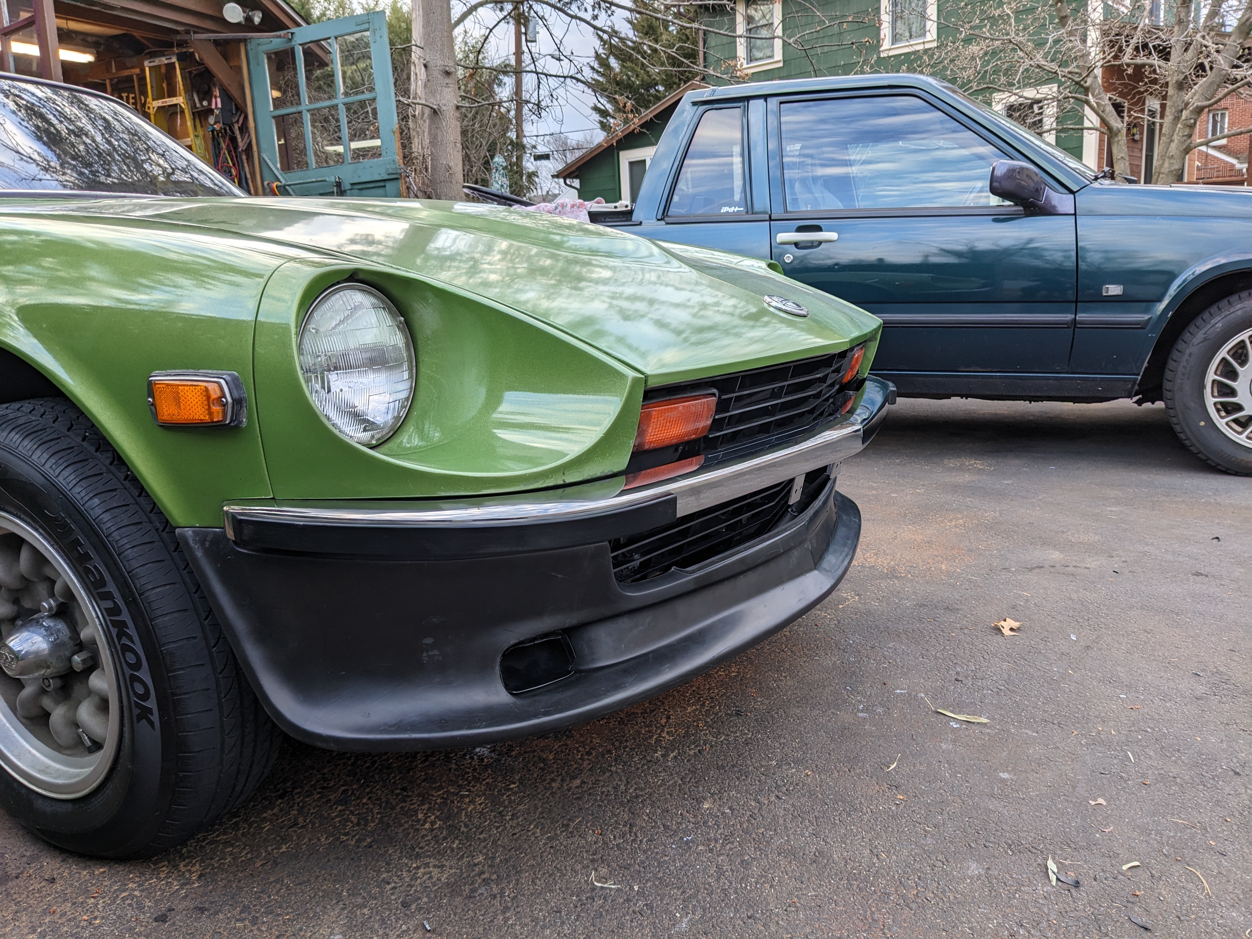
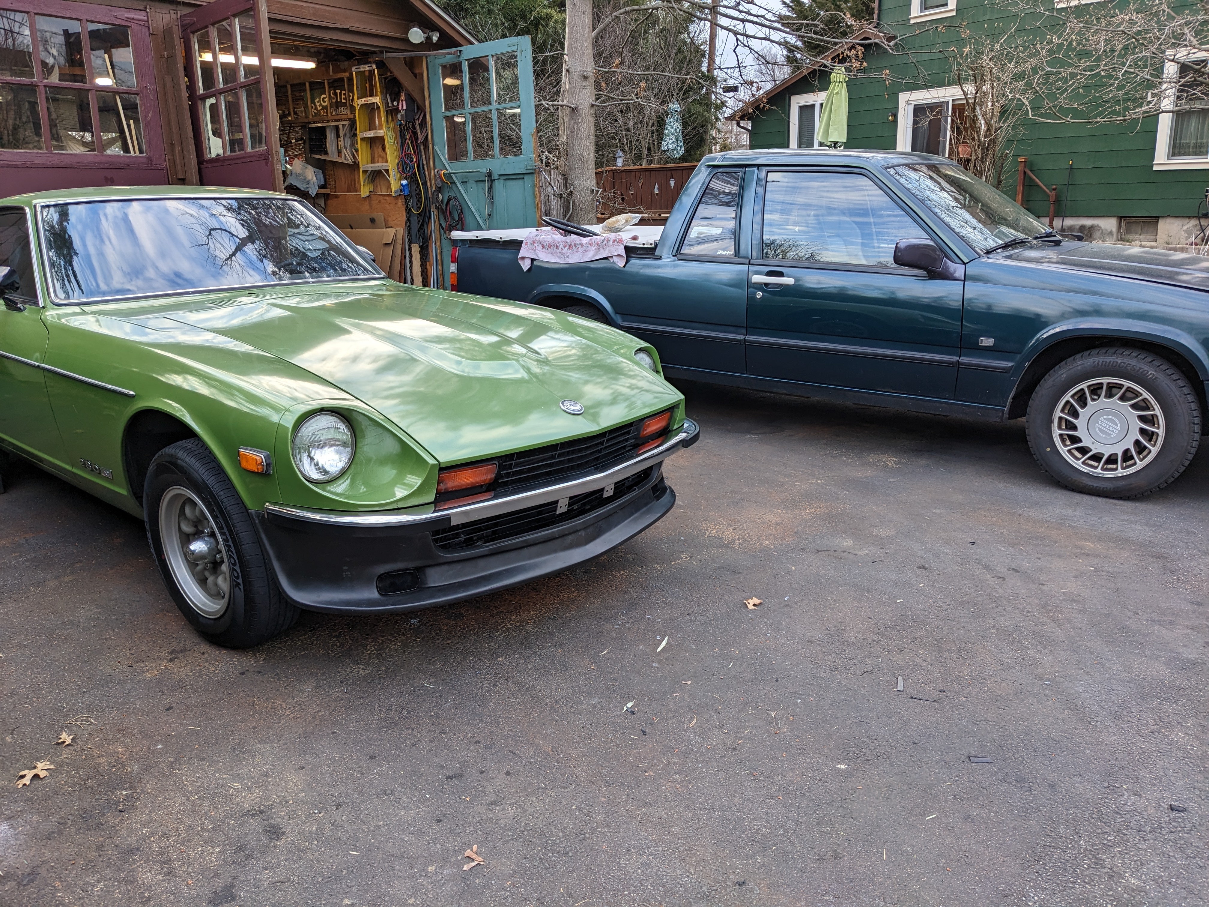
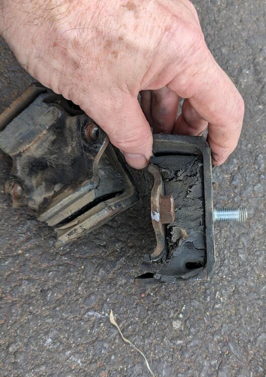
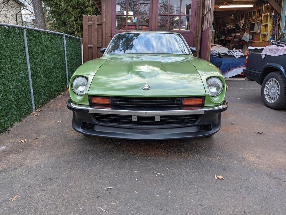
Finished the install after work - did the motor mounts first, since I had the car jacked up anyway. The car has 250K miles, I don't think he did any suspension bushings or any mounts in all that time. I'm happy with the fit & look. Not sure I needed to splurge for the Skillard grille, but I didn't want any of the gap I've seen without a full grille The bumper fit is very good


 1 point
 -
1 pointDear Zed Head, only to let you know that my Datsun is already running well. The problems I was having were due to an immobilizer linked to the ignition relay that was installed by the previous owner. I cut a wire that was energizing the ignition coil. Now problem solved.1 point
-
1 point'46' indicates Showa 46, which is 1971. Japanese calendar dates tend to follow USA format, which is Year-Month-Day, so '46-11-9' is November 9th 1971. This of course indicates manufacturing date and/or quality control check of the console, not of the car. It may even be for the FRP moulding of the console body and not the completed article. Consoles were made in another facility and then shipped in batches to Nissan Shatai's Hiratsuka plant for the build-up of the cars. The batches may well have been made up of consoles made over several days or even weeks, and it is doubtful that they were attached to cars in sequence according to the quality control date - although it is logical that they would normally have been attached to a car within a few weeks of production. I think it is fair to say that most quality control/production date stamps on the components of these cars tend to average out at within a month of the car being given its 'OK' completion check, although it is possible to observe the odd exception which tends to prove the rule...1 point
-
Google reviews on his company. https://www.ebay.com/itm/295560216805?hash=item44d0c300e5%3Ag%3A5U8AAOSwV4BfeS-O&amdata=enc%3AAQAHAAABEAU9fCdHyLszYfhfKQQjr6Luy%2FpSsZAoqfPz37lYFs3rV%2FPNhOsyKCk4N%2FDHDvxIQeje5qNXcaE576XyP83HvH33TzEv9P8cozdUXi12FHAOTsD1DE1LM1Ybb03HgxuoZqMveCNEFueTnDKRrORP7pnH61%2BlR0E10oPWD8RGpkblaDMFe3PZgWFZCS%2FoiQSHEAC4zvDufAMPIp70QJFGH6JCdAKFLN0UgHLA7BwOR%2BVlPyKWas3YGZWJ3EGuH82QaYNgYHjAuh2MJ9F9NpAe3nwNbG1N5eM%2Ffw0IdYuQjHjNb51Mp1Aipu32KvS%2FLt%2Fh4GKBnbWdtfZkkGOi9i6StFvFKyvTqxbrsYjVLtO6WmXB|tkp%3ABk9SR_6r4KDhYQ&fbclid=IwAR0Vd3V2dTIe_dQ-LnDDs3khaHTuRqYIwB4VDu3Bx8i36l9WsQCOWOKItkI1 point
-
Motorsport Auto has a good selection. Probably cheaper and of higher quality. The Classic mirrors are actually 60's Mustang mirrors. I had a set. They fit well and I liked the look but they were noisy in the wind. You could hear them with the window open. One of those things that you don't really think about. https://www.thezstore.com/product/926/classic-chrome-mirror https://www.thezstore.com/isearch3?searchterm=mirror1 point
-
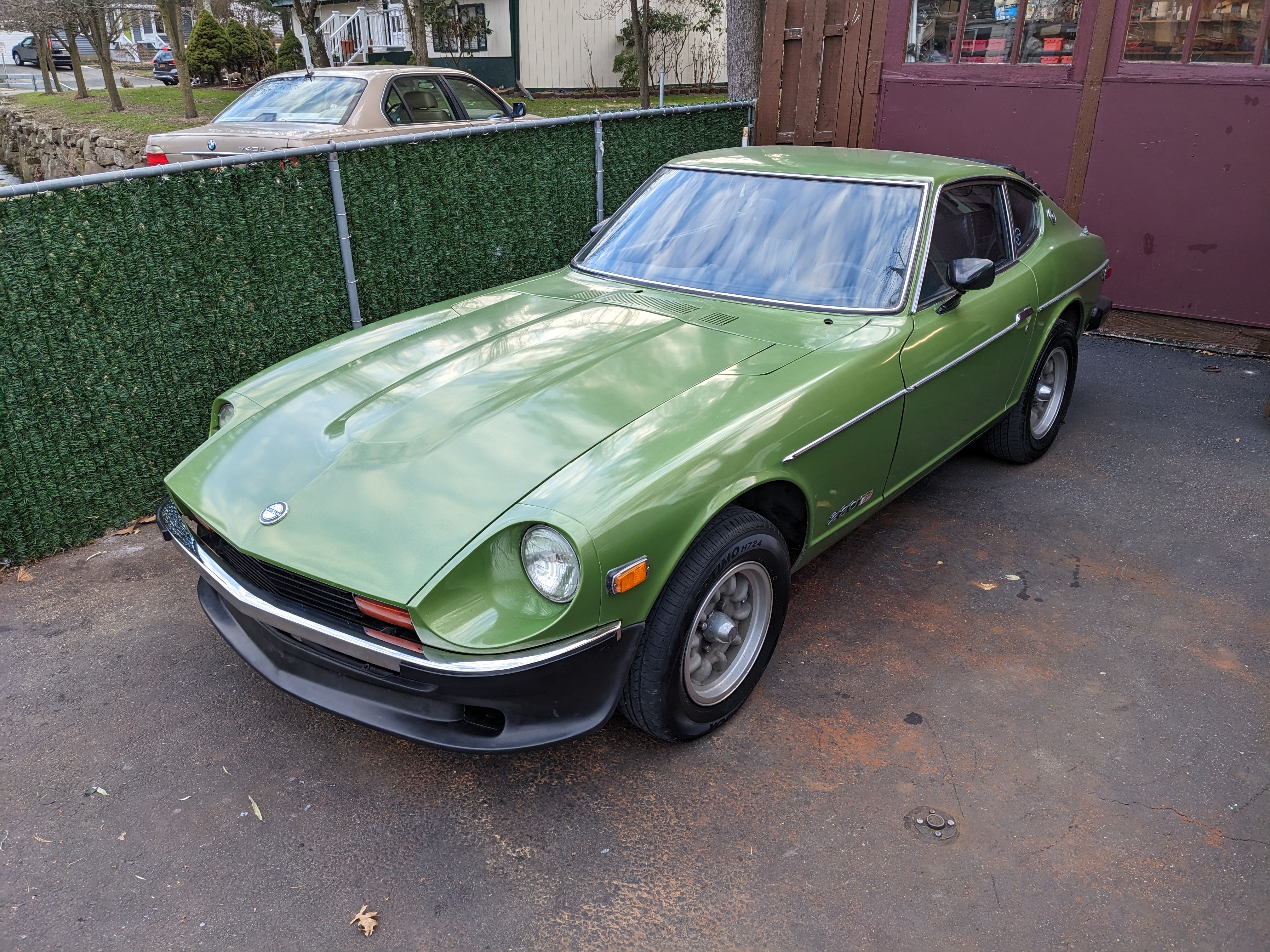
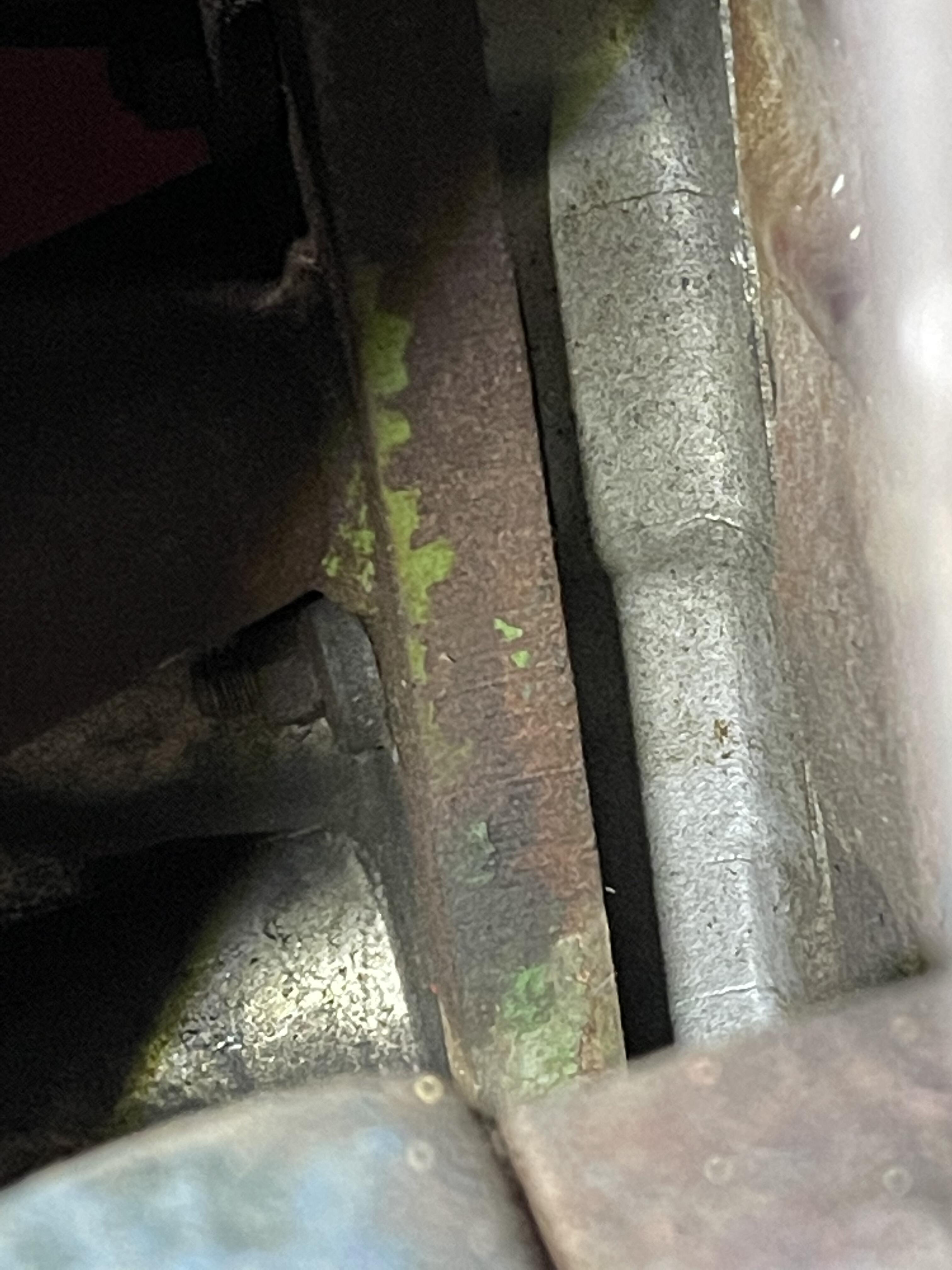
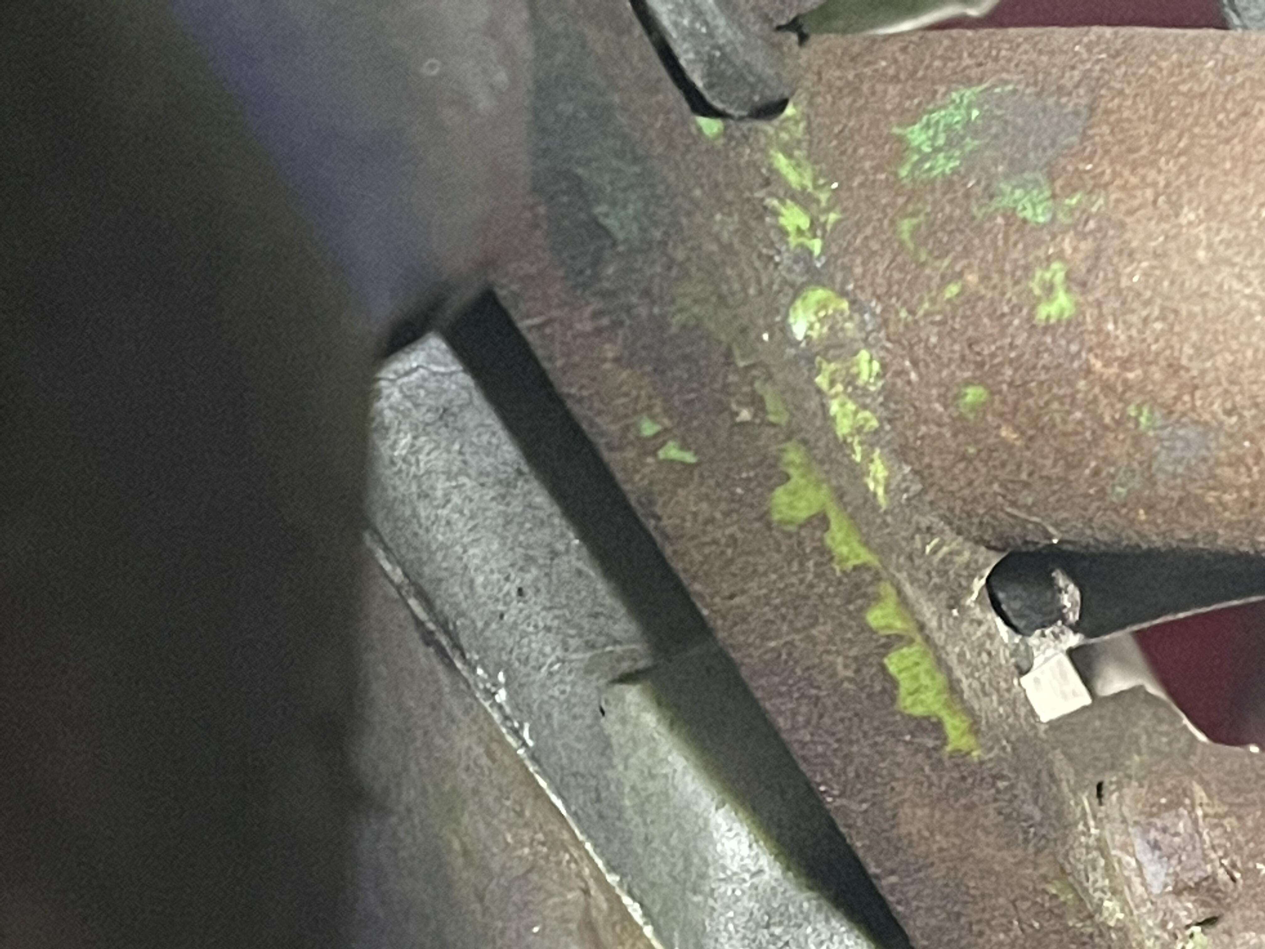
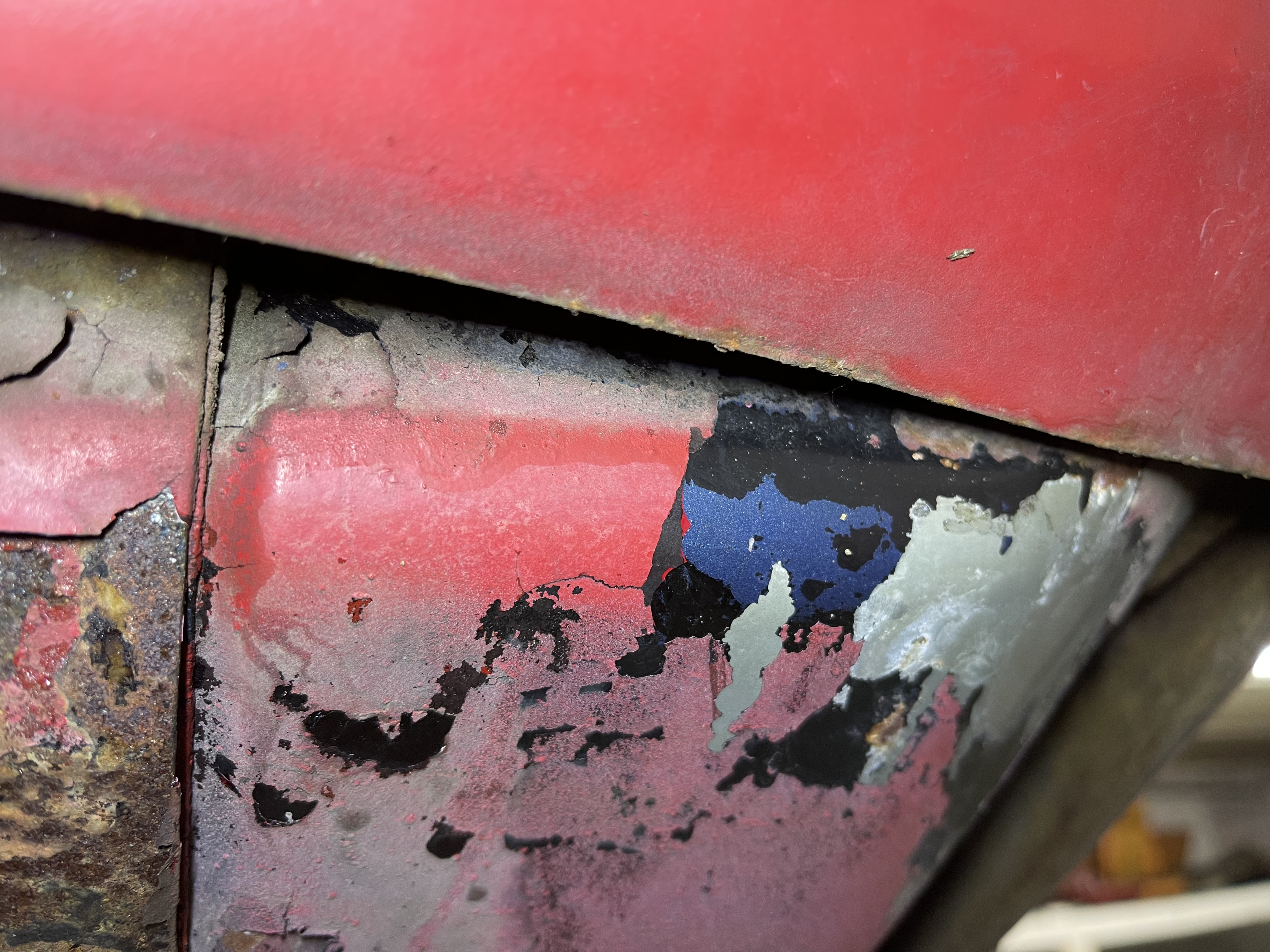
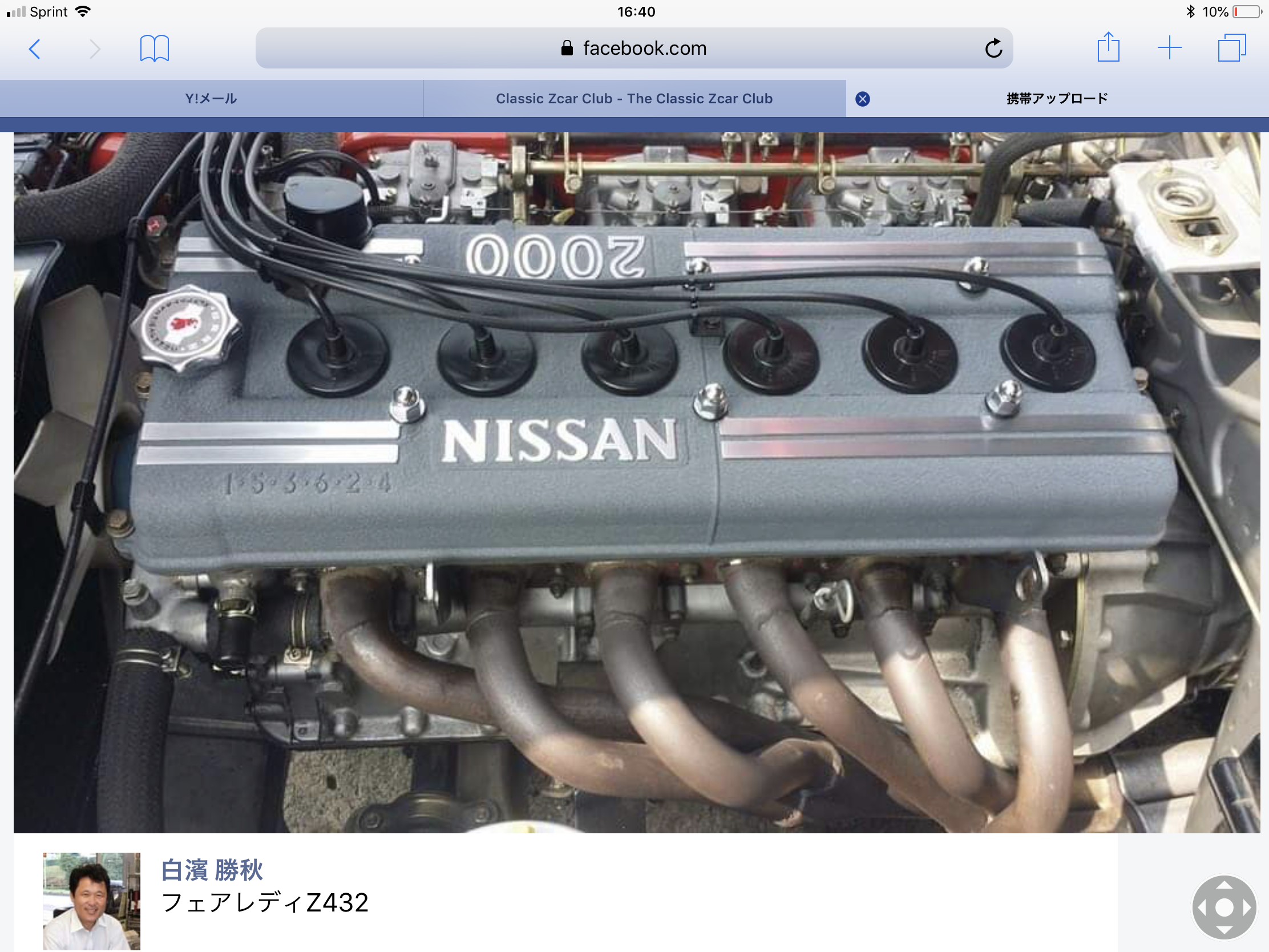
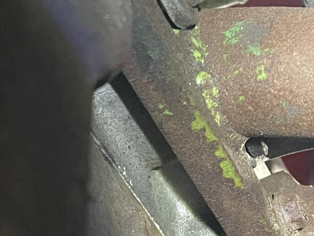
Interestingly, noticed the headers were at one time GREEN in color…… This car was a bright, flashy car roaming the streets of Japan at one time….. the metal vented fenders, green headers, 40phh solex mikunis, at one time gas tank shows it was blue in color as well….. Flashy, snazzy!!


 1 point
 -
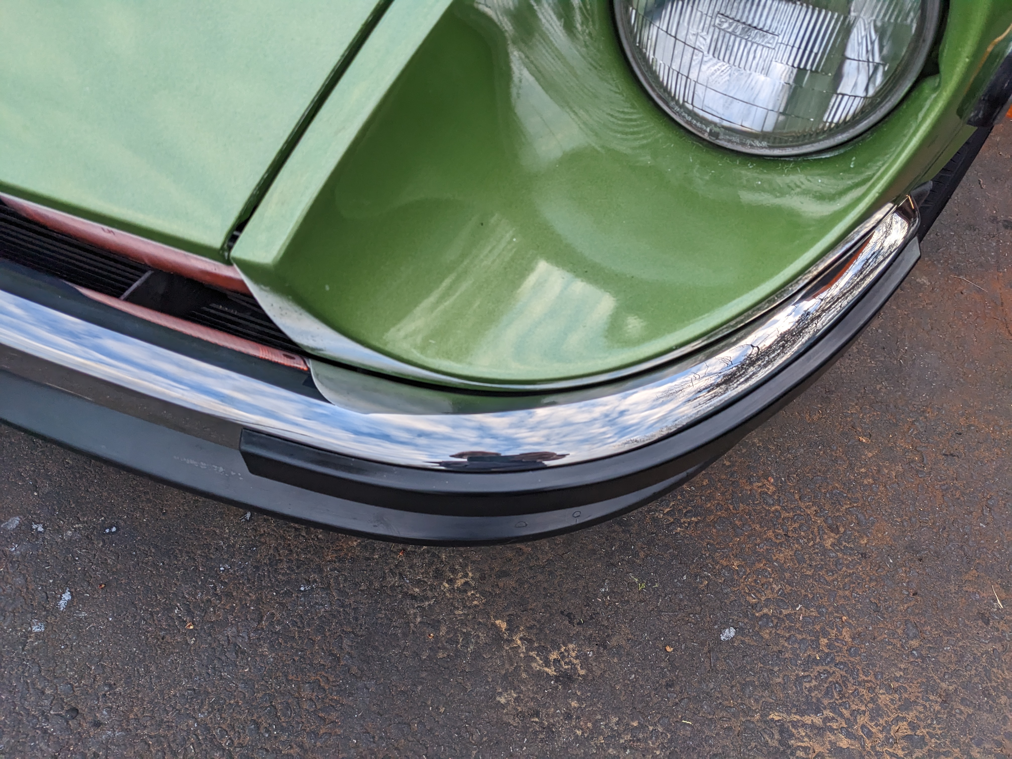
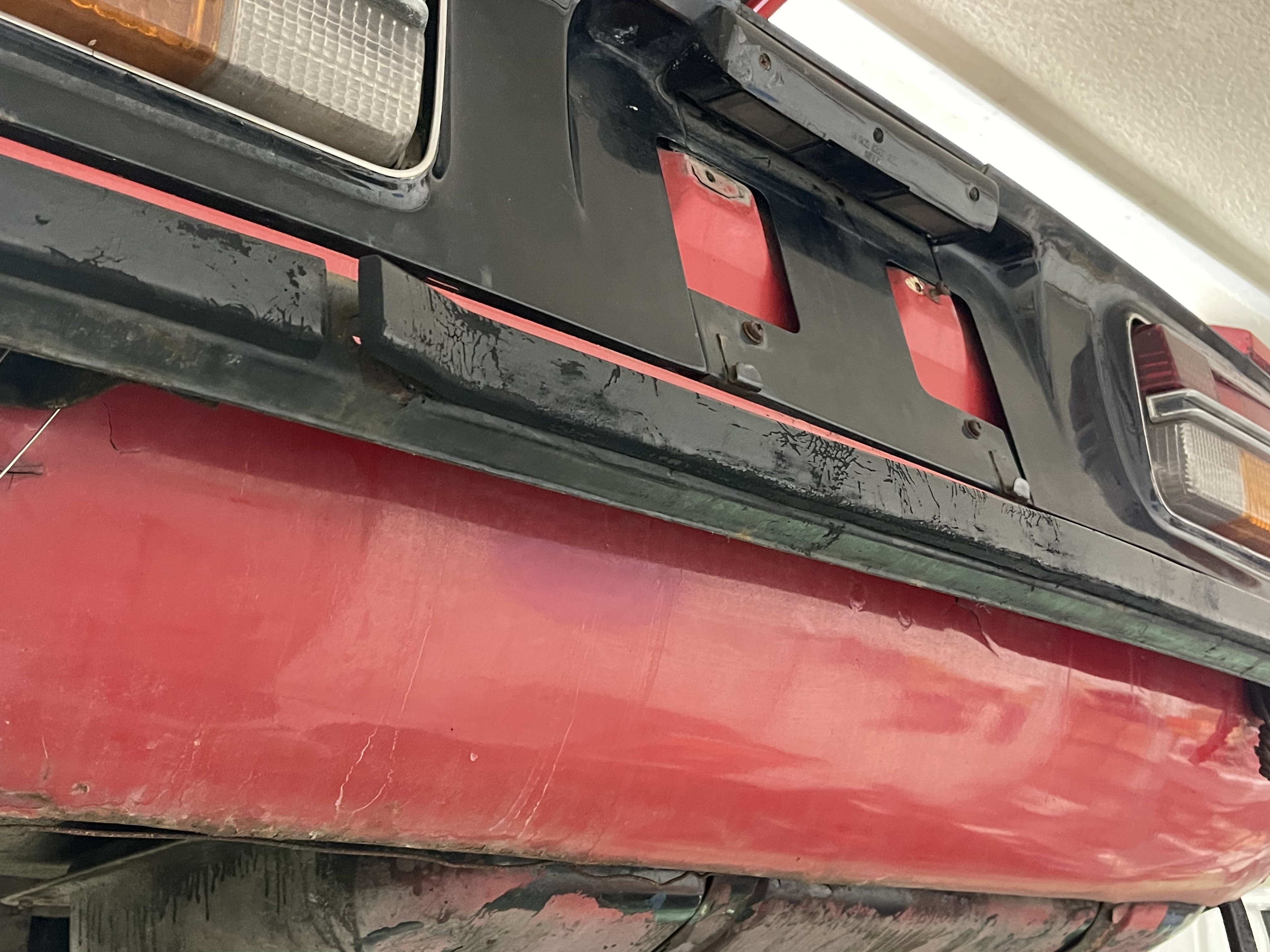
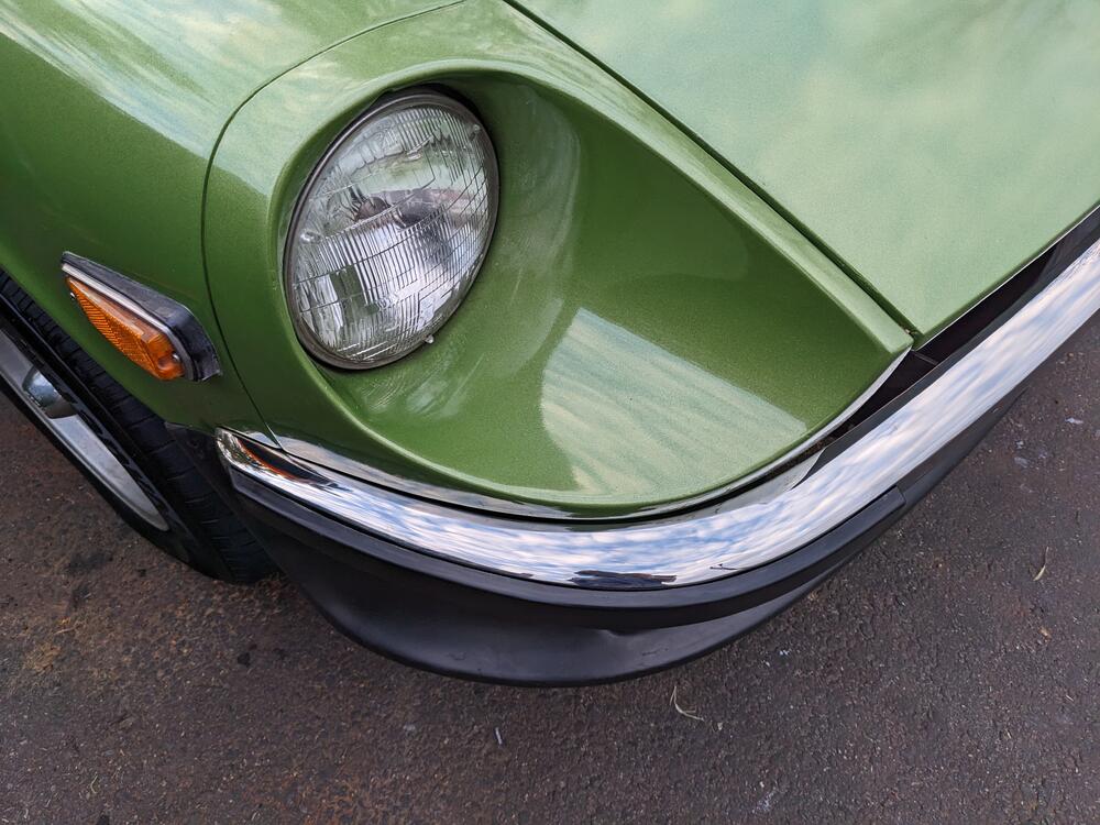
The rear bumper has been painted a gloss black to match the front and of course the rusty rockers. A quick peak on the inside “facing car” of bumper shows a maybe silver gray color…. Not chrome. There are no marks we’re bumper guards would have been attached… on second thought did any of HS30 car have bumper guards? Rubber strip is present in center of bumper although in poor shape.
 1 point
 -
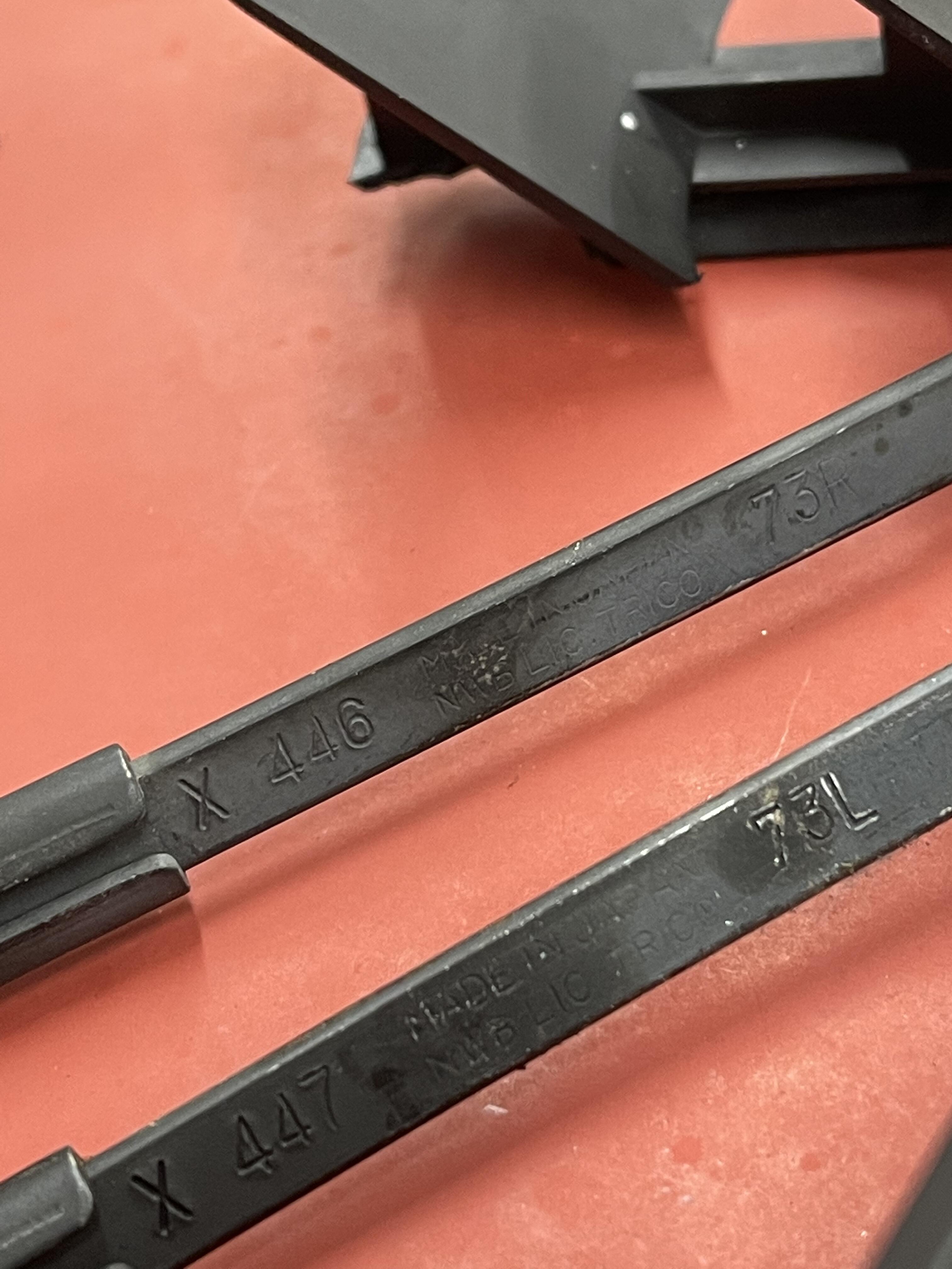
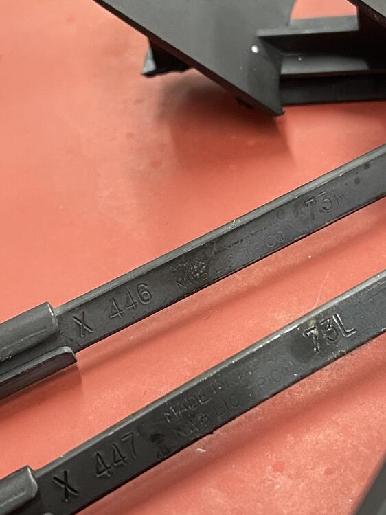
Wiper arms off the HS30 show 73R and 73L compared to the 4 sets of spares I have that are 55R and 55L……
 1 point