


.JPG.cfcada9cf1c1b502df3f5f2f2ca3ff36.JPG)

SteveJ
Community Member
-
Joined
-
Last visited
Everything posted by SteveJ
-
The main difference between the 260Z and 240Z fuel rails is the vapor line IIRC. There is a return on the 240Z fuel rail. I would install a fuel pressure gauge before the fuel rail without the FPR and check that. I found many pumps produce less fuel pressure than they advertise. Of course, I also didn't measure the voltage at the pumps to see if that could have caused the lack of pressure.
-
You have not provided enough information to give you an accurate answer. Why are you considering installing the Holley FPR? What fuel pump are you running? Will you be installing a fuel pressure gauge to set the FPR properly? Are you still using the stock fuel rail? It regulates the pressure with a fixed orifice. When I used a Holley fuel pump and FPR, I deleted the stock fuel rail and ran braided line to the carburetors. The order of the system was tank to filter to fuel pump to FPR. From the FPR one line went to the carburetors, and one line went to the return line back to the tank. I fabricated a custom heat shield to block the heat from the headers and ran the fuel lines closer to the carburetors as opposed to the stock fuel rail running near the valve cover. This made it where I didn't need to worry about heat soak.
-
I have three HF floor jacks. Two are full-sized aluminum, and one is a small steel model. They all have performed well for many, many years. I have jackstands that are over 20 years old (pre-recall) and look & work totally fine. Not all of their tools are one-use, but I wouldn't consider many heavy duty. HF actually has come out with higher line tools, too. I bought a couple of Daytona brand jacking dollies for a friend, and he bought two more. They work great for moving cars around in his garage. HF offers some tool chests that are similar to the quality that you find at the big box home improvement stores.
-
The blower motor part number is the same for AC and non-AC cars: 27161-N3600
-
-
-
You will need a probe that can reach inside the connector at the fuel pump relay. That will also mean you will need someone to move the flap in the AFM while you are measuring voltage. You will not see voltage for the fuel pump relay unless the key is in START or unless the key is in ON with the AFM flap open.
-
-
Don't look at the fuse. Pull and test for continuity or just replace. Fuses are cheap.
-
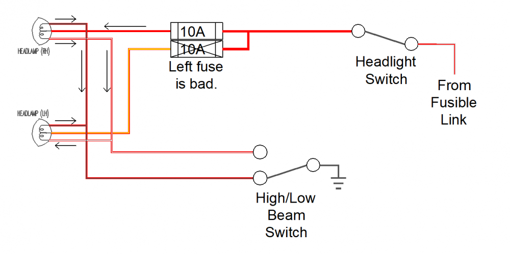
Again, it's most likely the fuse. One of the idiosyncrasies of the headlight wiring is that there is one positive to each headlight and two negatives. This is why a bad fuse shows up as a dim headlight. Here is a breakout of the circuit with arrows to show current flow with a positive to negative convention. Treat the filaments as resistors for modeling what it wrong, not as coils. Most of the current going through the right headlight is going through the high beam filament, to the red/black wire, to the high/low beam switch, and on to ground. However, the saying "Current follows the path of least resistance" isn't really correct. Actually MOST of the current will follow the path of least resistance. Some of the current can find an alternate path to ground. It goes through the low beam filament, over to the low beam filament of the left headlight via the white/red wire, through the high beam filament of the left headlight, and out to the red/black wire. The high beam of the right headlight sees enough current that the brightness appears normal. Meanwhile, the left headlight has about an amp flowing through it. If you were to measure the voltage drop across the filaments you would see something like this (with a 12VDC source): Right High Beam: 12VDC Right Low Beam 4.55 VDC Left Low Beam 4.55 VDC Left High Beam 2.90 VDC Light output falls off drastically with voltage (https://www.thetruthaboutcars.com/2019/06/piston-slap-droppin-knowledge-on-headlight-wiring-voltage-drop/), so that is why the left headlight is dim with the loss of the left headlight fuse. If you don't believe me, do this test. Find a 240Z/260Z/280Z that has stock headlight wiring (no relay conversions). Pull one of the two headlight fuses. Turn on the headlights. @Randalla I suggest you try my suggestion first. It is EASY to change a fuse. Change the left headlight fuse.
-
Two issues: 1. No low beams: The high/low beam switch is not making contact on the low beam setting. Sorry, I don't have it documented about taking it apart to clean/repair. 2. Dim driver's side: The headlights have a common grounding point, so unless the connector at the headlight is badly corroded, it is unlikely to be a ground. Check the fuse for the driver side headlight. Most likely it is blown, so the passenger side headlight is backfeeding through the driver side headlight. Several years ago, I documented how there is just enough current for you to see a dim headlight with a blown fuse.
-
I actually know the car and owner. I'm surprised he is listing with an open title. He has owned that car for close to a year. I could have sworn he had Georgia plates on it when I saw the car at his house. I know he has flipped boats in the past. As for the setting for the photos, he's a realtor, so he knows good locations for the photos. The hatch is sketchy from the rust around the bolt holes for the spoilers.
-
That's where I found them on the 78, and for the headlight relays, I was going to borrow power for the lights from the white/red wires on the ignition relays.
-
That is likely a timing issue or the intake valves aren't closing tightly enough. It's difficult to guess without examining the engine. However, I suggest you get your fuel system working right. In the meantime other things to consider is adjusting the valves. Adjusting them cold is not the preferred way, but it will work.
-
When I found the MIC parts in Google searches that gave links to TE Connectivity (current owner of the design), those pages had links to Mouser. Now if there was only a source for the old Yazaki rectangular connectors. Anyway, I think the 13 pin connectors are available from Mouser, so I guess I could make a plug-and-play relay solution for the 78. I don't think the 77 and earlier used the AMP MIC connectors. Would you happen to know? Now I started working on a CAD version of the 260Z wiring diagram. I'm not as skilled as @wal280z, but I need to teach myself more.
-
Same to you, Philip. Here's hoping to meet again at a future ZCON.
-
The 73 hazard switch is illuminated the same way.
-
Thank you for taking the time to wrap up the thread, and welcome to ClassicZCars.
-
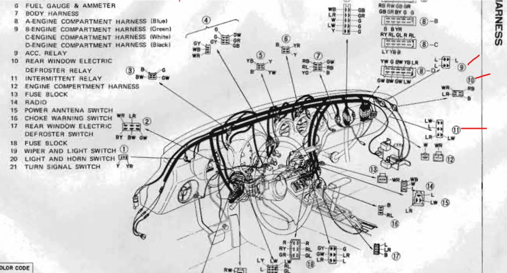
It takes some creative thinking, but BE-3 gives you your guide to mapping out the relays. What the drawing does is show the wire colors going to the connectors. Turn the page sideways and look toward the right side. From the connectors, follow the lines down to the relays. That shows you the stock relays.
-
Have you looked at the EE section of the 73 FSM? It's available on this website. Go to Resources and then Downloads. Also you probably have found the relays for the factory authorized/designed modification to add the electric fuel pump in the 73. I think the documentation on that is floating around in the downloads section, too.
-
Well, I have the terminals and connectors. They look like they should work. I ordered 3 sets of 7 pin connectors and 20 male/female terminals.
-


Important Information
By using this site, you agree to our Privacy Policy and Guidelines. We have placed cookies on your device to help make this website better. You can adjust your cookie settings, otherwise we'll assume you're okay to continue.