


.JPG.cfcada9cf1c1b502df3f5f2f2ca3ff36.JPG)

SteveJ
Community Member
-
Joined
-
Last visited
Everything posted by SteveJ
-
I believe August 17 to be exact...Take note ZCON 2021 attendees.
-
Heck, I didn't need to do much of a search to find him. 😉 It is *ahem* interesting to go through his feed. By the way, the marriage didn't last...

-
One of yesterday's photos...

-
I'm out. I'm hoping 2022 will be closer to me.
-
You are limited tire-wise by keeping the Iron Cross wheels. With it being a black/red 10AE, I suggest keeping the stock wheels. There were only 500 made, and the original wheels will help with maintaining the value. Having said that, the Radial T/As are about as good as you'll find. You can find Dunlop Direzzas in 14 inch but only 185/60. Using a tire size comparison website, that's about 8% smaller than stock on diameter. It might not look right in the wheel wells, and I would hesitate to drive on them in any other conditions than warm (or hot) and dry. The Falken Azenis RT660 might work better than the Dunlops, but with the same constraints on weather. It will still be a little small for the wheel wells.
-
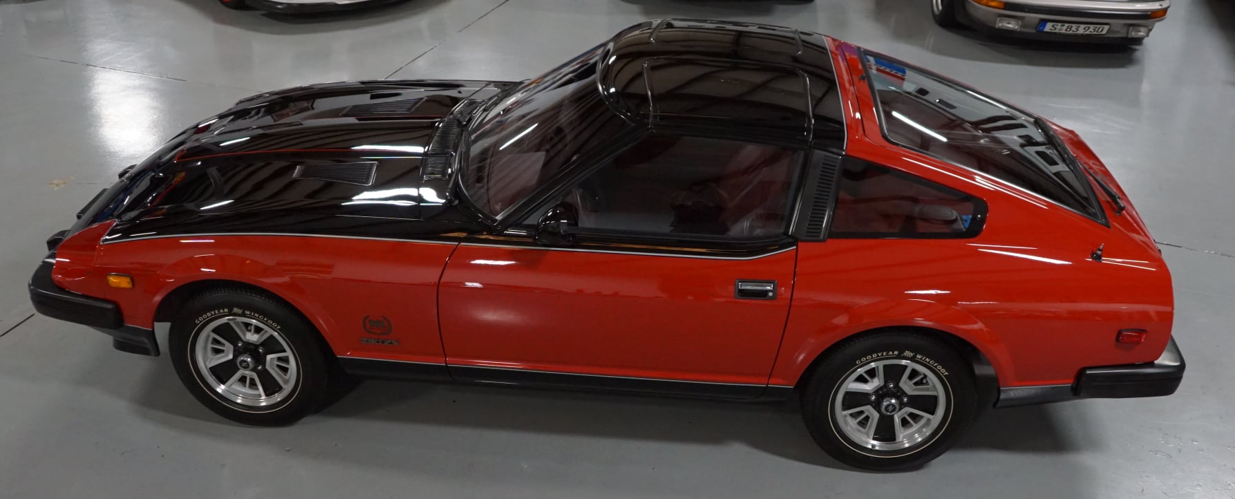
LOL, @siteunseenhas it right. I was shooting video at Randy Jaffe's shop today.
-
The young man who detailed the car is VERY good. I kept walking around the car to admire it. This is the holy grail of original 280ZXs.When checking for spark at the coil, this is what I did. And that was from a 280ZX distributor that had wobble in the shaft, so it didn't have the proper gap at the reluctor.Do you need to drop a hint about what your kids should get you for Father's Day? https://www.autozone.com/ratchets-sockets-and-wrenches/socket-set/duralast-10mm-socket-set-10-piece/582151_0_0?spps.s=3827&cmpid=LIA:US:EN:AD:NL:1000000:TLS:71700000060668368&gclid=Cj0KCQjw8IaGBhCHARIsAGIRRYrdJYwuRUVPbX4xGYByivEdXCmfN4kouAnXE0V4H-HS7NJd_3-iH4oaAqGfEALw_wcB&gclsrc=aw.ds Of course, the chances are that you'll lose them in the same places that you lost all of the others...
 Given all you have told us about the remote starter...maybe You might want to give the manufacturer/model of the product and post the wiring diagram that came with it. Do you have a manual or automatic transmission?Well, I guess I qualify for the group now...The old testing units are LONG gone from Nissan. Testing with the coil wire near the shock tower is one way. If you aren't ready to fix the issue with the ballast resistor, you can look for resistance to ground at the negative terminal of the coil. Holding the key in start, you should see the resistance fluctuate as the TIU closes the circuit to ground. As for plug and play? Nope. However, I did lay out most of what you would need to do to create an affordable alternative.It looks like it's the same between the 78 and 79.The problem with doing it in the engine bay is that the 260Z has a connector that does not match the 280Z distributor connections that you are thinking of. I didn't trace out all of the circuit paths for the B/Y vs B/W wires, so I included diodes to prevent backfeeding out of a sense of caution. However, from a more detailed look at the EE and EC section, I have determined that the B/Y wire would not be needed for the HEI conversion. Therefore the diodes aren't necessary. Here is the revised diagram.
 I'm not sure if the connector on the other TIU lines up. Do you feel adventurous enough to modify the ignition? With an HEI ignition module, a couple of diodes, a heat sink, heat sink paste, and a connector from Vintage connections, you could make a replacement ignition unit that would be pretty darn reliable for about half the price of that TIU you have in the last photo. (@Zed Head are saying the same thing.) Here is how you would wire the HEI for the TIU connector in the 260Z with the 6 pin rectangular connector. (Edit: Changed for the revised diagram in my later post.) Note: the connector as I have is drawn is a mirror image to the connector shown in the FSM wiring diagram per the Nissan drawing practices.
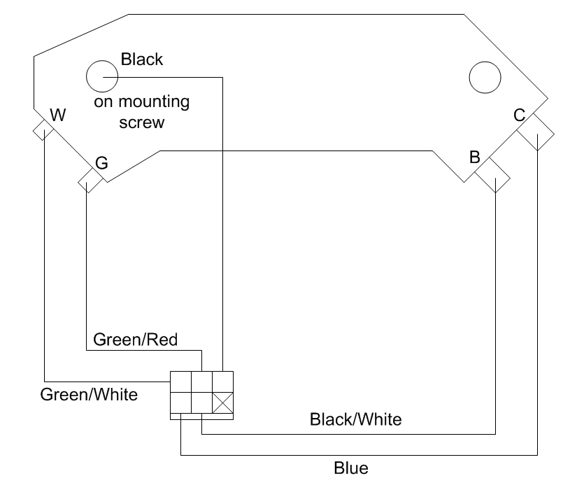 No, the relay won't work in the 78.But, but, but...they have been touched by the guys working at Gas Monkey Garage! 🙄You would want to test it the way I described. Your testing would not yield good results. With the ignition in ON, you would see voltage to ground at the positive and negative on the coil, except when the TIU is triggered by the distributor. (This is on a properly wired/functioning ignition.) For a stock configuration, it should be a white/black wire on the positive. The blue is on negative, as in your photo. The white black should go to the ballast resistor. There should be a black/blue on the middle terminal of the resistor (starting) and black/white on the opposite end of the resistor (running). The TIU is in the passenger footwell, likely on the firewall. Now, for the stray wire in your photo, you would have to clean it off enough to tell me what the wire color(s) is. My first guess is that it might be one of the wires that goes to the ballast resistor.
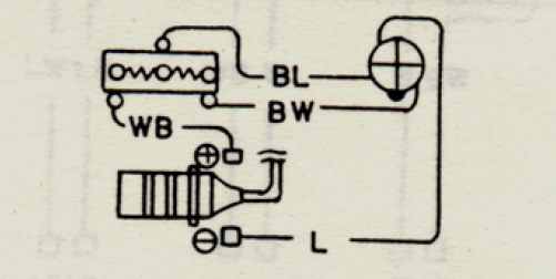 You said you're not an electrician, and now you're making me break out the electrical engineer. The coil is a step-up transformer. You are going from 12VDC up to 30,000 VDC or higher. The higher voltage will be induced when you have a complete circuit on the 12VDC side. However, if you have a complete circuit all of the time, you won't develop the magnetic fields on the primary side to induce the voltage on the high voltage side. When the engine is turning, the reluctor passes near the pick up coil in the distributor, and it creates a signal for the Transistor Ignition Unit to ground the blue wire. Current flows, a magnetic field is developed on the primary side, a voltage is induced on the secondary side, that induced voltage is at a high enough potential to overcome the resistant at the gap at the spark plug, and you have your spark. Now don't worry about much of anything in the previous paragraph until you REALLY want to understand ignition systems. With how you measured, you don't have power on either side of the coil. Power is voltage and current. You measured voltage on both sides of the coil. No, I'm not being pedantic. I hope this comes clear in a minute. In it's normal state, the ignition system is an OPEN circuit. With the key in the ON or START position, you are connecting it to the positive side of the battery. There is nothing connecting the ignition circuit to the negative side of the battery (ground) until the TIU connects it to ground. The primary side of the coil is just a long piece of wire, so it will have essentially the same potential at any point in that circuit. So the short answer is that you are using the meter properly, and you're probably seeing the voltage you should be seeing. If you are wondering whether or not the TIU is working, pull the coil wire off the distributor, with the coil wire connected to the coil. Position it close to one of the bolts on the shock tower (like about a 1/4 inch or so). Try to start the car. You should see the spark jump between the coil wire and shock tower.Charles has a good point, Shawn. Start with the easy stuff first. That would be the first paragraph in post #6. It sounds like the electric fuel pump operation will be more challenging for you to diagnose, but that's okay. Also, let's pause to talk about safety. There is a good chance you'll be needing to work around the gas tank. Do you have access to a lift or solid jack stands? Jack stand points are shown in the FSM. Wear safety glasses to keep all of that old grease out of your eyes, and your Covid mask will keep that crap out of your mouth (experience talking here). If you need to replace the hoses in the tank, drain the gas tank. There is a drain plug on the tank. Just make sure you have enough storage to catch the gas. I like using a huge oil catch pan (5 gallon) and have a couple of 5 gallon gas cans in case the tank was pretty full. Have plenty of 5/16 fuel line (low pressure fuel line will work). If you remove lines, do it section by section so you don't accidentally mix up your supply and return from the tank. As I mentioned before, if the fuel line around the electric fuel pump has never been touched, it is definitely old and brittle. When I dropped the tank to remove the rear bumper many years ago, those lines snapped like dried twigs. Have compressed air available to blow out the hard lines, too. It doesn't hurt. You may need to drop the tank and clean it out, too. That is a technically easy but time consuming process the first time you do it.The resistor value is 2.2kOhms.The relays are at the passenger kick panel near the fuse box. They are most easily identified by matching the wiring diagram to the relays.Yes, there are things not covered in the manuals. Trust me. I've spent years reading posts on this site and others to learn. However, do not discount what is in those manuals, such as the location of the filter and the relays. 😉 Your fuel problems could be anything from junk in the tank, to a clogged filter or pump, to a cracked hose that lets air into the system. The maps for most of the things you want to test/inspect are in the FSM. For the filter, look at page FE-7, just don't look for the word filter. The relays can be more of a challenge to test, but they can be tested. You'll need a voltage source (a 9 volt battery can work for this) and a multimeter set to resistance to check the contacts. You use the voltage source to activate the relay and ensure the contacts operate properly. When you have the materials together to test, we can go more into the details of testing. That way you don't have to search through as many posts. Also familiarize yourself on how relays work if you haven't played with them before. https://www.explainthatstuff.com/howrelayswork.html As for the asbestos, yes, the insulation on the fuel rail is asbestos. It's mostly a sleeping dog. If you don't disturb it, nothing happens. If you need to move it some, wet it down well before touching it so it doesn't throw off as many fibers.


Important Information
By using this site, you agree to our Privacy Policy and Guidelines. We have placed cookies on your device to help make this website better. You can adjust your cookie settings, otherwise we'll assume you're okay to continue.