Captain Obvious
Community Member
-
Joined
-
Last visited
Everything posted by Captain Obvious
-
According to the documentation, there are two diodes and resistor inside the original fuel injection relay. For me, the question is "Does that Bosch relay have those three two additional internal components?"
-
Because (as mentioned above), 95% is not 100%. Since your in the flight business... If 100 flights were to come into your local airport and 95% of them landed safely. And, of course, one other possibility is that it's a mutation variant that is able to slip through the existing vaccine. That's why even if you don't think you need it for yourself, do it for all the other people you come into contact with. We're all in this together and if you don't get vaccinated, you're potentially the Petri dish for the virus to mutate. If you want to get back to normal, get your vaccine!!
-
Here's a couple threads with info on compressing the bumper shocks: https://www.classiczcars.com/forums/topic/55336-collapsing-shocks-to-push-bumpers-closer-to-body/ https://www.classiczcars.com/forums/topic/64753-depressing-early-260z-bumper-struts/
-
Wait... Are you asking if I've done something just like that? https://www.youtube.com/watch?v=VomBuudIDsM
-
Won't work. You'll be able to calculus the living crap out of it, but the car just doesn't respond to Fourier transforms, Laplace Transforms, OR diffy Q.
-
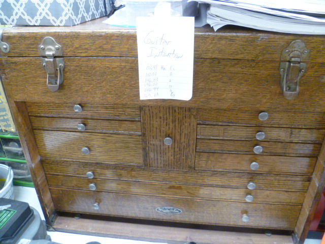
My Gerstner. It's absolutely the centerpiece of my workbench. I got it a number of years ago from a retired machinist who used it for decades at his work. When he was showing it to me, he was pointing out blemishes and little scars and telling me that it would be pretty easy to strip it and refinish it. I asked him why would I spend time taking out all the history and personality that he so lovingly put into it? He beamed.
-
Close enough. 78 FSM says .20 intake, and .25 exhaust. Both cold. The interesting thing (for me) would be to try to figure out why yours are adjusted so tight. Was it a mistake by the last person who was in there, or has something moved and closed up the gap over the last bunch of miles? Unless the adjuster lock nuts are loose or something, it'll probably be impossible to determine, but I'd spend some small amount of time trying.
-
Make sure you put the flare nut on before you flare the tubing.
-
Make sure you put the flare nut on before you flare the tubing.
-
They make specific "glass buffing" stuff... Cerium oxide. I've not looked into the specifics, but I assume it's harder than what they use in paint compounds.
-
Before you scrape it, I would try some solvents. Acetone, Methanol. Maybe some paint remover? Might get lucky and find something that will just wipe it off?
-
I can already tell you that the lash on most of your valves is too tight. The back side (non-lobe side) of the lobes should never be clean like that. That's a sign that the valves are never completely closing and the base circle is rubbing all the way around. And valves that never close can make some strange noises sometimes. I can hope that it's as simple as that?
-
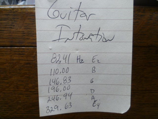
This is hanging on my toolbox for a task I've been meaning to get to:
-
pogden, Sounds like great progress. And to add a little more detail to what Steve mentioned above... The Volt warning lamp does more than just light up when there's an issue. It also supplies "bootstrap" current to the alternator system to get it up and working properly when you first start the car. As you found out, you should use an incandescent bulb in that application or things might not work right. Obviously.
-
Yeah, I'd be happy to help if it weren't at the opposite corner of the state. Upper left corner is about seven or eight hours away from the lower right. I agree on the purpose of those plastic plugs... Back in the old days, they would drill holes, stick a wand in to spray rust preventative goop inside and then plug the holes with caps like that. The most well known company was "Ziebart". I can't believe they went right through the VIN tag though. "My boss says I need to put the holes one foot apart. So I put the holes one foot apart. That's my job."
-
Just trying to do my part. For solidarity, I got lucky too. Did a happy dance:

-
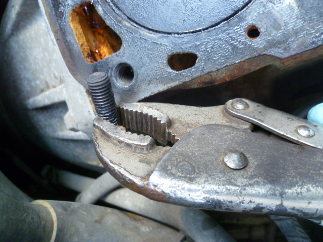
There's no way I would reuse that bolt. I would chuck up the remains of the bolt in the lathe and drill a hole in the end. Do the same thing to the threaded stump, and then turn a metal dowel pin to fit the holes. Press the dowel pin into place to align the two while you run a small weld bead around where it broke. If your welding skills are good, they say "the weld is stronger than the base metal".
-
-
Interesting... Pretty much everything sounds like it's working OK, but the engine is starving for fuel once you get above idle. So to answer some questions: Yes, it is possible for the EGR to be stuck open even if there's no vacuum applied. But that would cause an issue across all operation conditions, especially idle. If the EGR is stuck wide open, I doubt you'd be able to get a steady idle at all. Same for the PCV if it were stuck open. Sounds like a classic fuel capacity issue, but your fuel pressure up at the rail is OK. Maybe your fuel injectors are partially clogged? They can pass enough fuel at idle (because the engine just doesn't need that much fuel at idle), but when you're taxing them to pass more fuel than that, they can't. There are little screen filter cups on the inlets to the fuel injectors. Maybe they are partially plugged with crud? Maybe the injectors themselves are plugged, or sticky, or both? I'm not sure your conclusions are valid. You're running a tiny bit rich at idle (12.7 - 13.0) which is fine, but just because you can sometimes nurse it up to 3500 doesn't mean you've really got the flow capacity. An engine with no load will "run" with an extremely lean mixture. What's the A/F ratio when you manage to nurse it to 3500? To me, it sounds like you're a little rich at idle, and as the RPM's go up, you get a little leaner, and a little leaner, and a little leaner, until it's finally so lean that it just won't run at all.
-
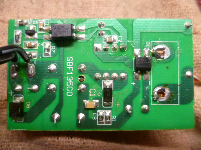
I've got one of those too. Not nearly as clean, but works fine. Honestly though, my current go-to is my "old" Harbor Freight trickle charger. It's pretty much a constant current source limited to about 1/2 Amp up to about 12.5 Volts, and then drops the current off above that. By the time you get to 14V it'll give the battery whatever it'll take (which is usually in the milliamp range). At one point, I burned it up. Not sure how, but I let the smoke out. So I figured (since they're disposable) that I would just buy a replacement at HF. Well unfortunately, it turns out that they changed the design... The "old" one still has a step-down transformer in the wall-wart, but the "new" one is a semi-conductor switcher like the other new junk. Hated it. (Men On Film). I mean, don't get me wrong... it's all cheap Chinese junk. But the older junk is better than the newer junk. They took most of the copper out and replaced it with Silicon. So in the end, I reverse engineered my "old" HF charger and fixed it. Anyone surprised? Here's the old one all fixed and also sporting a potentiometer mod to adjust the output voltage: And here's the new one. Flyback switcher with opto-coupler feedback loop. Don't like it at all:

-
What the old chargers did with a lot of copper and iron (in the form of a transformer), the new ones do with semiconductors. And in today's age, silicon is a lot cheaper than copper. So the bottom line is that most of the new chargers now have silicon components where the old transformers used to be. The way of the world. Lightweight silicon and software instead of heavy copper and capacitors.
-
So we've known eachother for how many years... And you're just figuring that out? Na-Nu Na-Nu.
-
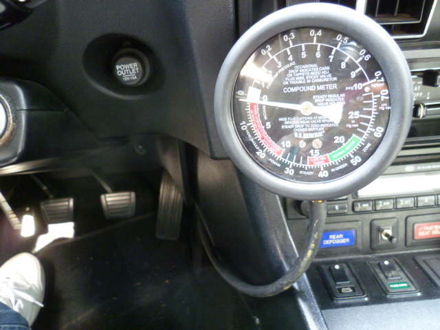
I think that since everything is essentially dead ended (or at least should be), there's enough vacuum for everybody. Why don't you "T" a vacuum gauge into the line and drive around like that a little. You'll get a feel for where the vacuum peaks. And if it peaks somewhere other than light cruise, you might need to come up with some sort of alternative. I believe the ignition advance tops out somewhere around 15-20 in Hg. I don't know anything about the big bore TB. Other than it's got a big bore.
-
I think that the shape of the hole(s) are also as important as the sizes. For example, if I theorize way above my pay grade, I would imagine the shape of the distributor advance goes like this... They wanted a very narrow spike of vacuum oat a specific pedal position, so they used a narrow slit. And I can affirm (from driving around with a vacuum gauge T'd into that line) that the vacuum spike is very narrow and very high (vacuum). The EGR ports on the other hand, appear to be placed to provide vacuum over a much broader pedal position. I'm guessing the smaller hole in the back is used to "extend" the EGR vacuum value deeper into the throttle. So my read on the whole thing is... They optimized the ignition advance to kick in only at one narrow pedal position (light cruise), but the EGR is activated over a broader range and deeper into the pedal (medium cruise). But, neither of those ports will produce any significant vacuum once you get above medium cruise.
-
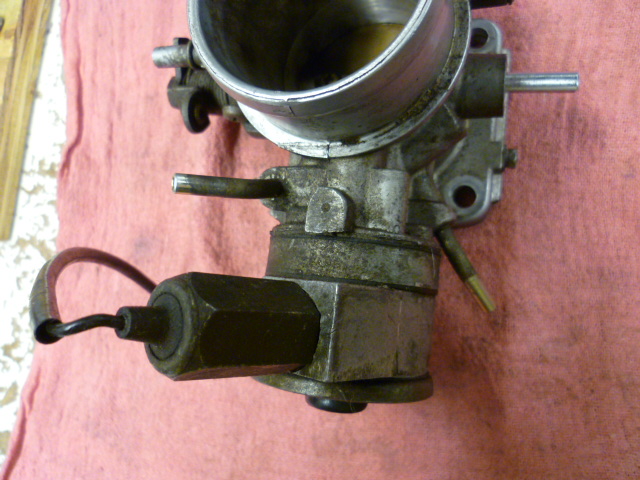
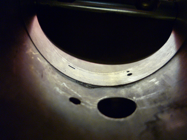
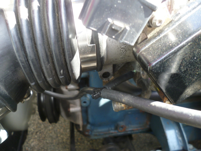
As Site mentioned above, the original throttle body has two ported vacuum sources. One for the EGR and the other shared by both the carbon can and the distributor vacuum. Here's another pic showing the two vacuum nipples: And about the idea of sharing the same ported source for all three things (distributor, EGR, and vacuum can), it'll "work", but you can tell from the placement and size of the original vacuum holes that Datsun wanted different vacuum profiles for the two different ports. Here's a pic down inside the throat of the original throttle body. The three small holes in the back are for the ported vacuum sources. (The two larger holes in the foreground are for the BCDD). The narrow slit hole on the left is for the distributor and CARB can. And the pair of holes on the right are for the EGR. You can see by looking at the shape, size, and position of the holes, that they will have different vacuum profiles at different pedal positions. Looks like this: So I'm thinking that it'll "work", but the vacuum profiles won't be the same as stock. Then again... Who's to say that your one ported vacuum source is the same as either stock port anyway?