


Captain Obvious
Community Member
-
Joined
-
Last visited
Everything posted by Captain Obvious
-
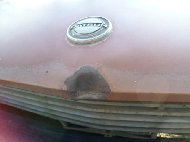
For the collective, here's a pic of the dent on the nose of the hood I mentioned above. For those of you with body experience... How hard of a repair is this? I know everything is repairable with enough time and effort, but where on the scale does this fall?
-
Sending you PM...
-
I believe my buddy @GGRIII (you met him at my place at the wheel bearing party) has the original hood from his 260. It has the traditional parking lot dent on the front point, but other than that, I believe it's straight. He was going to fix it but found a near perfect replacement instead that saved him some time when he did his car. Would you like me to find out if it's for sale or if he had plans for it?
-
I sure do and I bet I'm not the only one!
-
LOL! Whew!! Close call!
-
I've got a tiny (tiny) bit of molding experience, and in my miniscule experience, it can be really really hard to fill a cavity and have all the air be properly displaced by the filling liquid. Since the block and head (not to mention the heater system) are rough and complex internal shapes, I would be very very surprised if you can just pour water into the radiator cap hole and have 100% of the air in the system be exchanged with water on the first try. I bet there would be significant pockets of air remaining after the fill. And that's where the overflow system comes into play. Putting some rough numbers on it... The volume of air in the system will expand closely related to the ideal gas law, while the volume of water in the system will expand at a much smaller rate. Quick search on the web says the volumetric coefficient of expansion for water is .00021 while air is .0036 . In other words, for the same temperature change, air expands about seventeen times more in volume than water does. That can certainly cause a vurp. It is my belief that the air will eventually be trapped in the filler neck as bubbles circulate in the system. The filler neck acting as a vertical trap as the bubbles flow by and getting pushed out the overflow when the system pressure increases. Then (assuming an overflow bottle is connected and has liquid in it) when the system cools down and contracts, it will pull liquid back in where the air used to be. I also do not believe this happens all at once, but can happen over a number of warm-up / cool-down cycles after filling. So... The bottom line? I think you should connect up the overflow tank, put some coolant in it, top off the radiator, and then heat cycle the system a couple times. If you are watching the tank, you might even see some bubbles burp out. If that's the case, the level in the overflow tank will end up a little lower than when you started because some of that liquid will be pulled into the system. And after a couple cycles, hopefully you would have all the air worked out.
-
My point about the gas being compressible means that it might not be fine. Just because it doesn't overpower the spring in the cap and push anything out, doesn't mean it's OK. In fact... When the system is working properly, there is SUPPOSED to be some liquid pushed out of the cap and into the tank. Then when it cools, that liquid is supposed to be pulled back in. With the cap on, if you aren't getting anything at all pushed out, that is another indication that you might have air in the system.
-
About the burping... I suspect it could just be an air pocket somewhere that hadn't worked it's way out. If you've got a gas bubble anywhere in the system, it will expand a huge amount compared to an equal volume of liquid and can push vurps of liquid out like that. The recovery tank and two way valve built into the radiator cap is intended to eventually work that gas out of the system and replace it with liquid. The gas is also compressible though, and it will compress first, before the system reaches the cracking pressure of the cap. If you have too much gas in the system, you may never even reach that cracking pressure because the gas will just compress. So with that in mind... Do you have a recovery tank installed or are have you been running open system?
-
Why yes... Yes, it does. Enjoy.
-
Welcome to the club! You are reading the manual correctly. There should be nothing connected to the anti-stall dashpot. Even though it looks like a vacuum nipple, there shouldn't be any hoes on it. The dashpot should just be left open. And a couple of the other vacuum lines are mixed up accordingly. The non-California 76 cars (which it appears yours is) used a system to disable the distributor vacuum advance until the car is in top gear. Not sure why they thought this was necessary, but in 77, they decided this was not necessary and eliminated that feature. So if I'm reading the manual correctly (pages EC-9 and ET-1), it appears the three-way line from the throttle chamber should go to: Throttle chamber connection Carbon canister control Timing control solenoid valve And then the other side of the timing control solenoid valve should go to the distributor advance connection. So where in PA are you?
-
I'm glad the story was that boring! Although a harrowing hair raising saga would have been much more entertaining! And I'm also glad that you've got a set of hubs put together now that are issue-free. And if you've got a gap between the flange and the outboard bearing, that's definitely a raging clue as to the previous issue. 1.6 thousandths can be a LOT when talking about bearings. Just for forensic analysis... See if you can determine if that gap is the same all the way around the bearing. If it's the same all the way around, in theory it shouldn't cause what you saw. But if it's .0016 on one side and zero on the other (which is what I suspect), then it's indicative that something is bent or you got some piece of grit or metal shaving trapped under the bearing race. In any event, it's almost definitely related to the problem.
-
I don't think the contact cleaner drying out is what is causing the change. I think there's something else going on. Are you sure something is really changing, or is possibly a placebo effect?
-
Clearly (and not surprisingly), there are people viewing both this ClassicZ thread and that BAT sale. Right after I brought it up here, they started talking about the dash cap on BAT and they're all over it now. It's an easy issue to fix. Expensive, but simple. "there has been some discussion of this car on a prominent Z car website, Classiczcars.com" Woot. We're prominent!! So just to be clear... I don't see anywhere where the seller ever portrayed this car to be a "completely correct" example. So all the chatter from people (like me) about the things that are "wrong" is info for the next owner who wants to make it better. That car isn't done, but it's a beautiful starting point!
-
Beautiful car. I took a quick look through the comments and I think there is more of an issue with the tone of voice being used to point out some of the incorrectness, rather than the incorrectness itself. The insinuation of questionable intent: "i just find it to be very strange how you own over 15 Z cars and you dont know ...... Just like you didnt know .... lol. or maybe for some reason you are pretended not to know but indeed you do.. what ever it may be." Uhhh.... OK. Something I see that I'm surprised that hasn't been mentioned... That's a dash cap screwed into place, right? That bugs me. Also, the shift knob... It's the "right" Nissan knob, but it's still wrong. And there was some discussion about the carb correctness... The car is said to currently sport three screw SU's and the seller says they are the correct carbs for the year. I though three screws were used in 72 only? I'm no expert, but I thought a 70 car should carry four screw SU's.
-
Oh wow! That's cool. And brave!! Those sort of journeys are often good stories. Was it an entertaining eventful journey, or was it a smooth sailing boring story?
-
I like the shot next to the original wood knob. That's a great contrast between old and new!
-
Haha!! Good luck! So out of curiosity, what year are you working on anyway?
-
I was taught that if one foot on the floor didn't stop it, you should put two feet on the floor and get up. You aren't going to fall asleep anyway.
-
Great news on the polarity confirmation. And also great news that the engine is running well! Don't forget to put a timing light on it though. You do still have to set the base timing.
-
My son who recently graduated from VT went through that exact same thing. There was one class that was questionable up to the end and nobody could be 100% sure until the diploma arrived in the mail. Hope it all works out!!
-
Haha!! My engineering sense tells me that the boundary condition would be when/if the pendulum ever reaches forty-five degrees to horizontal. Beyond that, it would be unrecoverable because the force pulling down would be greater than the force you could ever create even if you moved it laterally at infinite speed. At least that's what the vectors in my head tell me. And you're right! It's beer time!! Right now! Good night folks!!
-
Can't wait. Hopefully we have a smoking gun. It's always a great feeling when that happens!
-
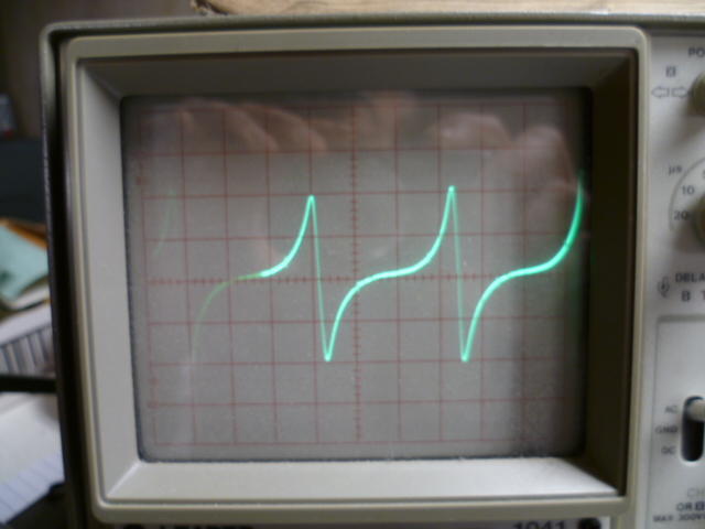
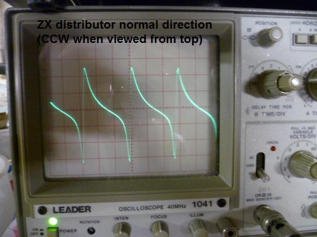
I also believe that the original ignition modules are looking for the negative to positive going transition. And as Zed Head mentioned, if you get them hooked up backwards, you end up with a lot of spark scatter and unpredictability. It's because you are spending a whole lot of time in the transition zone with a slow changing signal. Kinda like a very slow ramp on a CMOS input. They don't like it and can go indeterminate. You want the slope as vertical as possible and if you get it hooked up backwards, it can go metastable. The only predictable area is physical transition when the reluctor stops approaching and starts retreating. At that point, the magnetic field change reverses, and the induced current will reverse as well. And... If that's not all... (we talked about the amplitude before being proportional to the speed of rotation) When designed correctly, the signal slope at the transition point is relatively unaffected by the rotational speed unlike the slope elsewhere which is very dependent on rotational speed. If I haven't beaten this to death yet, here's a pic showing the waveform with the polarity switched. Note that the important positive going transitions are that flat indeterminate area with almost zero slope. Bad. What you really want is infinite slope on the positive going transitions. Here's the wrong polarity: And here's what the waveform should look like. Note that the positive going transitions are the vertical slope areas. Correct polarity:
-
I disagree. I know it's all past news now and doesn't even matter, but I would have done it differently. I would have ignored the motor, the drive amp, and all the rotational stuff at the left end of the track. I would have also ignored the viscous damping. Focus on the forces required to keep the pendulum vertical. Write those equations first in a perfect simplified world and then once you have that part done add in the complexity of the damping and a rotational drive. But to start, assume linear motion, frictionless surfaces, and no damping. First task is to just keep the pendulum upright. Once you have that, add in the other factors one at a time.
-
That's one of my favorite Far Side cartoons ever. I've even heard that "My brain is full" phrase uttered in technical project meetings. Maybe even by me...


