


There are a few threads floating around in the Topics section that deal with refreshing and/or upgrading the Z's Heater system. None of them offer much help for gaskets. Here, for the first time (I think) is a set of printable templates for the full set of gaskets that you'll need to put your 240Z Heater system back together in a factory-equivalent fashion. These templates were developed as part of the work I'm doing on my 1970 240. I know they're good for the 1970-71 cars, I think they're good for the 1972-73 cars, and I believe they might be ok for the 260Z as well.
Restoring a 240Z Heater System (gasket templates included)
I've debated for some time whether to attempt posting my experiences in restoring the heater system for my 70 Z -- there are already a couple of similar postings in the 240-260-280 Z Topics section on this site. However, none of them really has much to offer in the way of assistance for creating all of the (many) foam gaskets that are required to do the job properly. Since there's been some member interest expressed recently in getting access to templates for these gaskets, I've decided it's time to contribute my efforts as a new installation in the Articles section. I hope they save you some time and effort.
Application
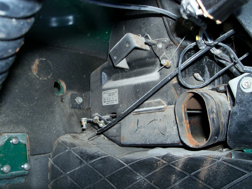
My experiences (and the photos and templates posted here) come from the work I've been doing in restoring the Interior of my 70 Z. After looking at the Parts Fiche diagrams and part numbers for the 240Z's Heater system, I don't see any change in the main parts throughout the various 240 models (1969 - 1973) -- excepting the Heater Core/Matrix (same dimensions, but the orientation of the inlet/outlet pipes is a bit different). So: everything that appears here should be ok for your 240. If you're working on a 260Z or a 280Z, you'll need to verify whether the gasket shapes are the same or different (the Heater Box changed from an end-plate design to a centre-split design at some point along the way). And if you've got a 280ZX, all bets are off.
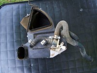
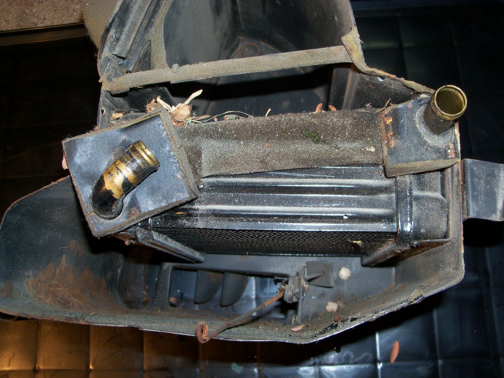
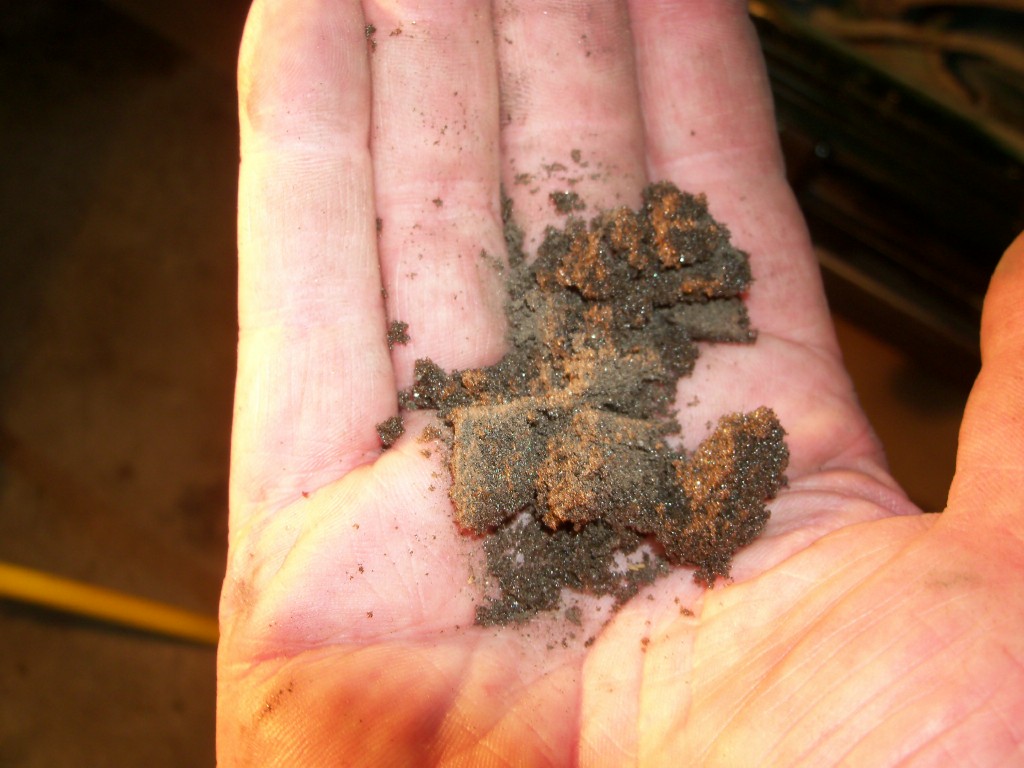
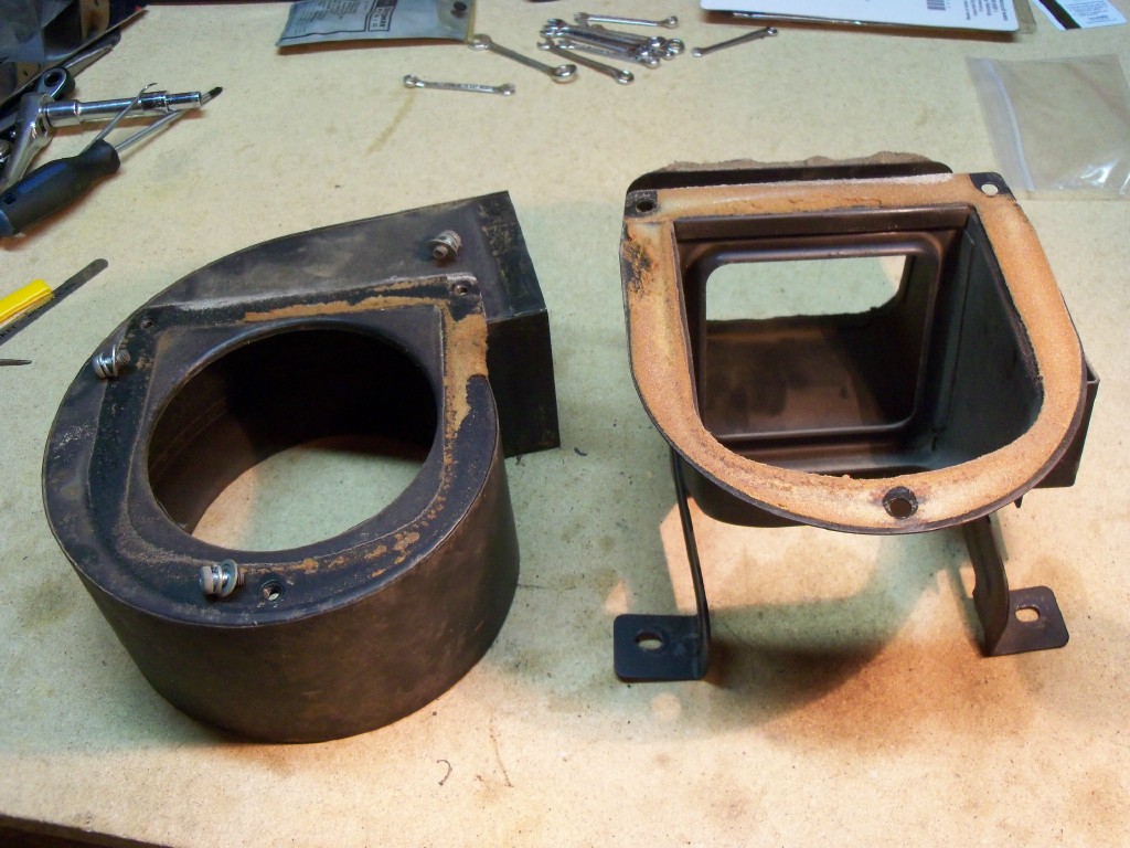
My heater system was in the, 'rode hard, put away wet' condition when I pulled it out of the car and stripped it down. Fortunately, though, the corrosion was minimal and a pressure test of the heater core performed by my local rad shop showed that it was good to put back in the car (a relief, because the Series 1 heater cores are hard to find).
Disassembly
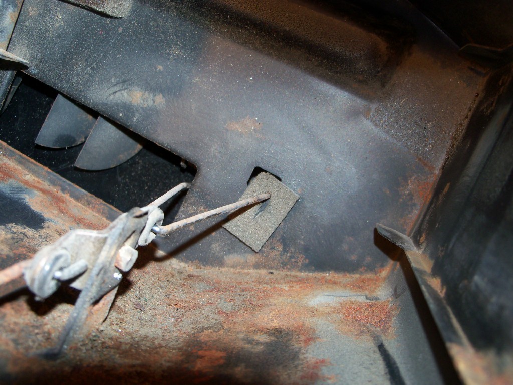
Pulling the assemblies apart is pretty self-explanatory. Just remember to take lots of photos and label-and-bag the parts (they look different when you come back to them after a week or two hiatus). Hopefully, your system (unlike mine) won't have shed any of its parts or suffered abuse at the hands of a PO.
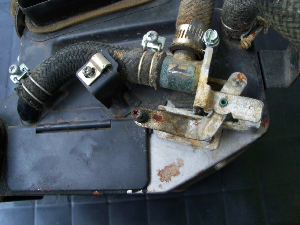
Heater Control Valve
The most likely piece of the system to require replacement will be the Heater Control Valve. Mine was seized. However, a week-long soak in 'CLR' calcium-lime remover loosened things up very nicely. It doesn't appear to leak, either, but I still need to verify that with a proper pressure test. Leaks in this valve are usually down to the small rubber washer that seals around the in-out control rod. If your valve shows signs of leakage from this spot, I'm afraid that the only solution is to going to be the purchase of a complete new valve (pricey, but available from several sources). The little seal for the control rod used to be available from NAPA, but as of 2016 it appears to be NLA.
Cleaning and Painting
You can (and should) clean out all of the nooks and crannies with compressed air. Strip off all of the old gaskets and clean up the surfaces in preparation for installing new ones. One member has recently reported good experiences from using muriatic acid for this task. Be careful of eyes, skin, and breathing if you try this. And don't even think about doing it indoors or in your garage! (the vapours will corrode every bit of exposed steel in your shop - i.e. all of your tools, parts, and machines).
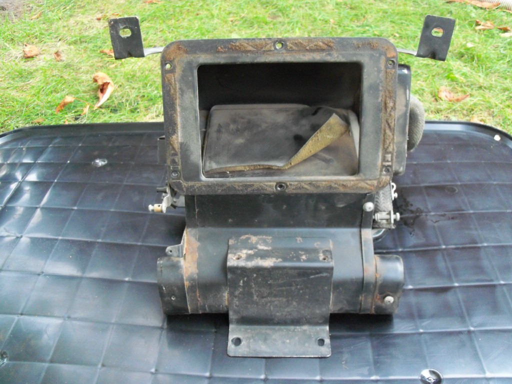
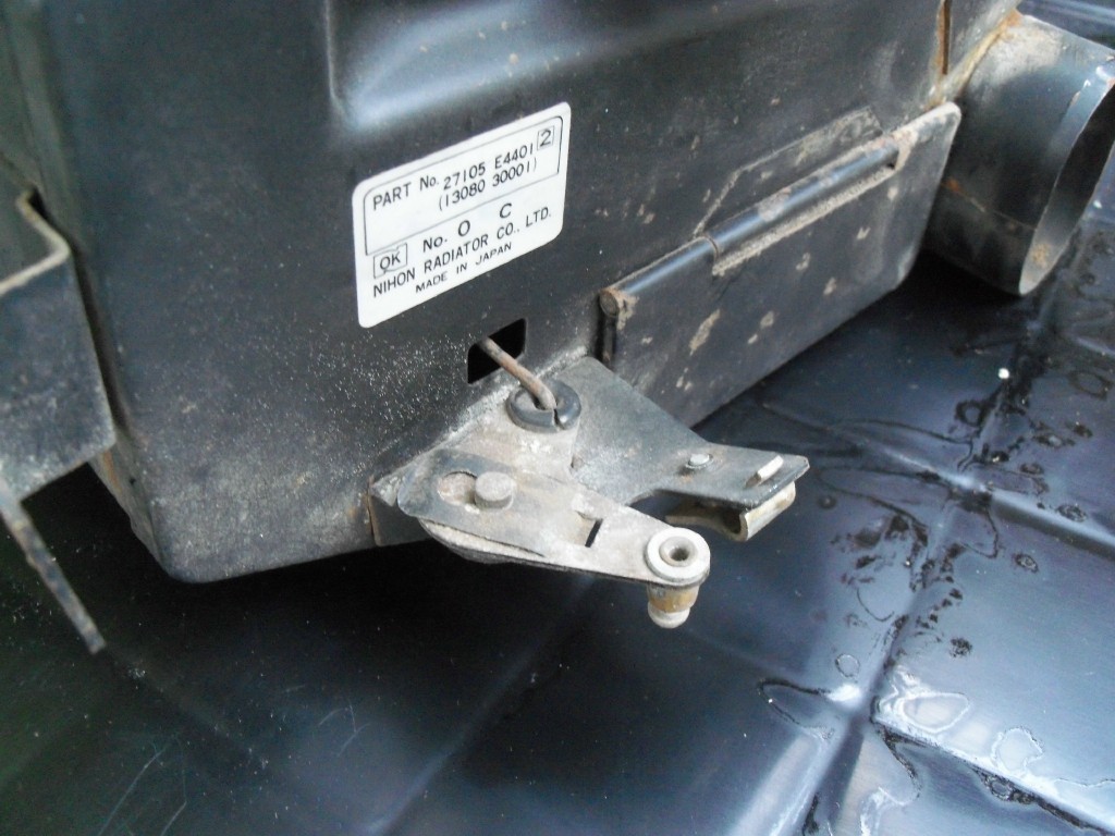
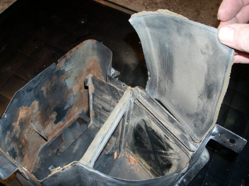
Heater Box -- After you've removed any remaining crud and rust, I recommend painting the inside surfaces with a zinc-rich primer to help stave off any future corrosion. After you finish this job, I think you'll agree that you don't ever want to have to pull this unit out from under the dash again, so an anti-rust treatment makes sense. Make sure that the various airflow control flaps are operating freely and aren't bent. There are two big ones and two little ones. Remember to add a drop of oil to all of the hinges and pivots. When everything looks good mechanically, finish up by painting the outside of the main (metal) housings with a fresh coat of satin-finish black. Carefully mask off any decals before you apply the paint (I think there's just one).
Re-Assembly & Gaskets
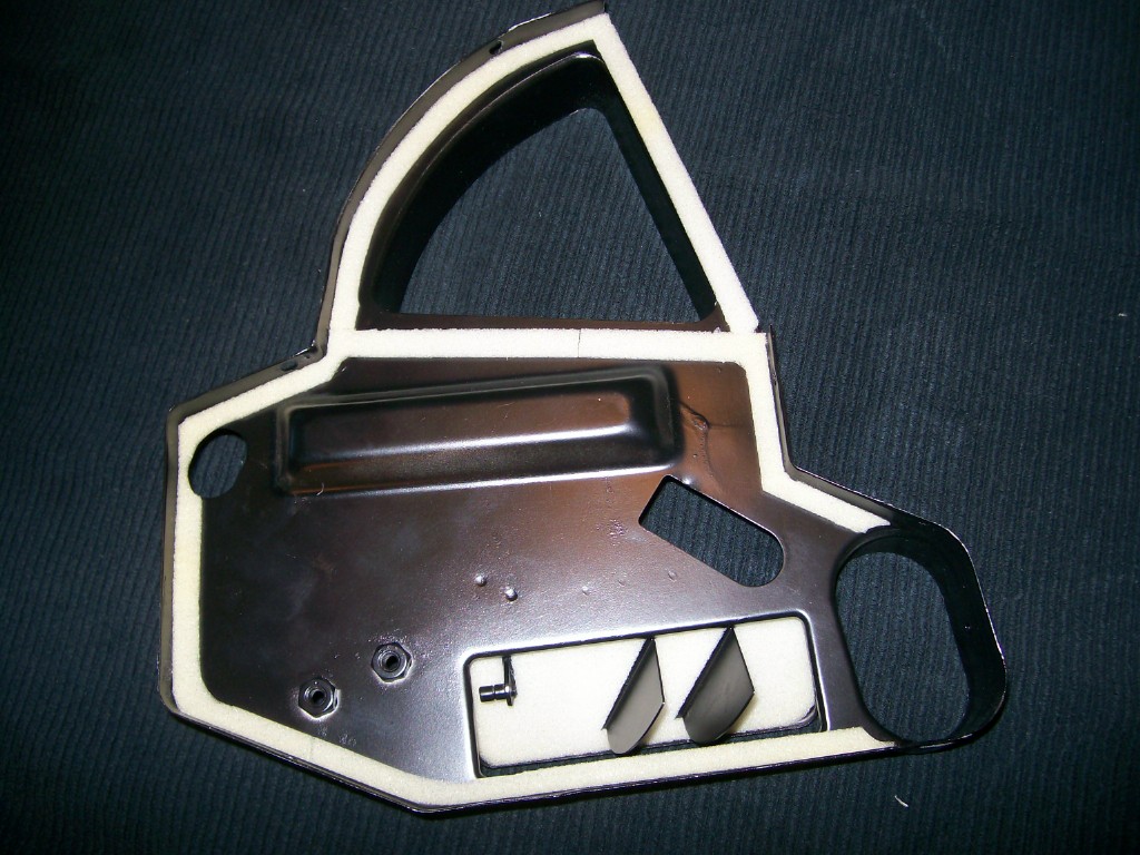
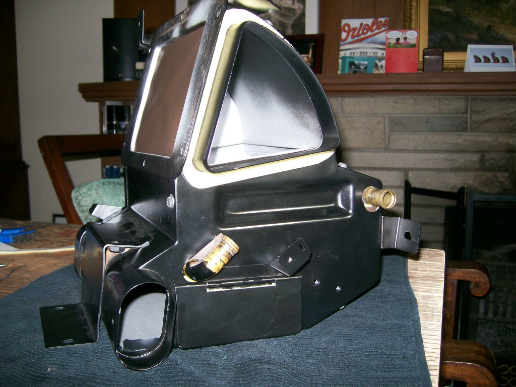
Once again, this is pretty self-explanatory so most of my discussion here applies to the foam gaskets. The pictures here will help to remind you how everything goes back together.
I made my gasket templates the hard way (drawn or traced by hand). Once done, I decided that I needed some insurance in case I made a mistake in cutting or during installation, so I tried scanning one of them into a .pdf file using my computer's scanner. A print-out afterwards proved that the .pdf file generated a new paper copy that was 100% accurate in size. That uncertainty removed, I scanned all the rest of the templates to generate a complete* set. The result was a set of digital templates that can be re-used ad infinitum. They're attached here. You can download the entire set, or just the ones you need for your particular job. Here's how to put them to use:
Cutting and Applying
Most of the gaskets used at the joins for the ducts and housings are very thin. I used 1/8" dressmaker's foam and it seemed to be about right in most cases (1/4" dressmaker's foam might offer a bit more resistance to tears, but it seemed too thick to me). This type of foam is open-cell and quite soft. I'm not sure about its long-term durability for automotive applications, but I suspect that it'll be good for at least five years. It's not easy to work with, though - stretchy and floppy while being handled and, of course, it has no adhesive. I came up with my own solution to this problem, but I've since become aware of a much better alternative!
I recommend that you use the 1/16"-thick closed-cell foam that's sold at art supply shops in 8-1/2" x 11" sheets (visit your local Michael's or Joanne's store). This is available in one-sided adhesive form, with a strip-off paper backing sheet. All you need to do, then, is print off the gasket templates and then glue them onto the backing sheet. Presto! You're ready to start cutting.
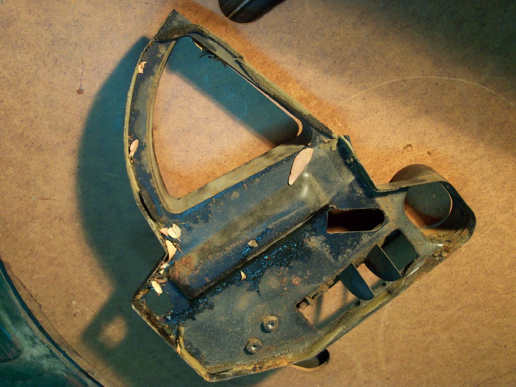
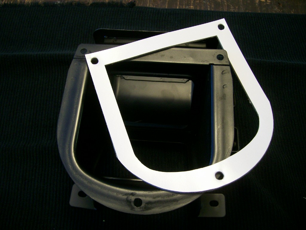
You'll probably need a soft foam for the gasket the seals between the windshield cowl panel and the 'Air Intake Compartment' housing. This gasket needs to be made from closed-cell foam in order to provide an effective water seal. While you can buy sheet neoprene in a 3/16" thickness and you might be able to use it here, I'd be concerned that it may be too hard (durometer) to provide enough compliance for this particular application. Whatever you use, you may need to consider using some kind of sealant for the gasket surface that seats against the cowl. Just make sure that the sealant and the foam that you use are compatible with one another. Do a trial application on a piece of foam scrap before you commit. Let is sit for a few days to see what happens.
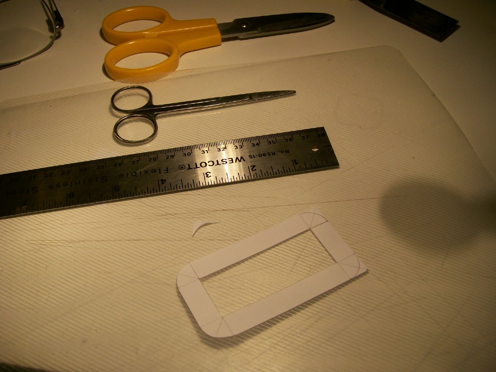
If you're in a hurry and not too worried about neatness, you can just use scissors to do most of the cutting of the gaskets. Just remember that not all scissors are created equal and a crappy pair of scissors will make for a poor job. I've had very good results using Olfa-brand scissors. If you want to do a tidier job with nice straight edges, though, you'll need to use a steel straight-edge and a razor knife. You'll still need the scissors for the contoured sections and the radiused inside and outside corners.
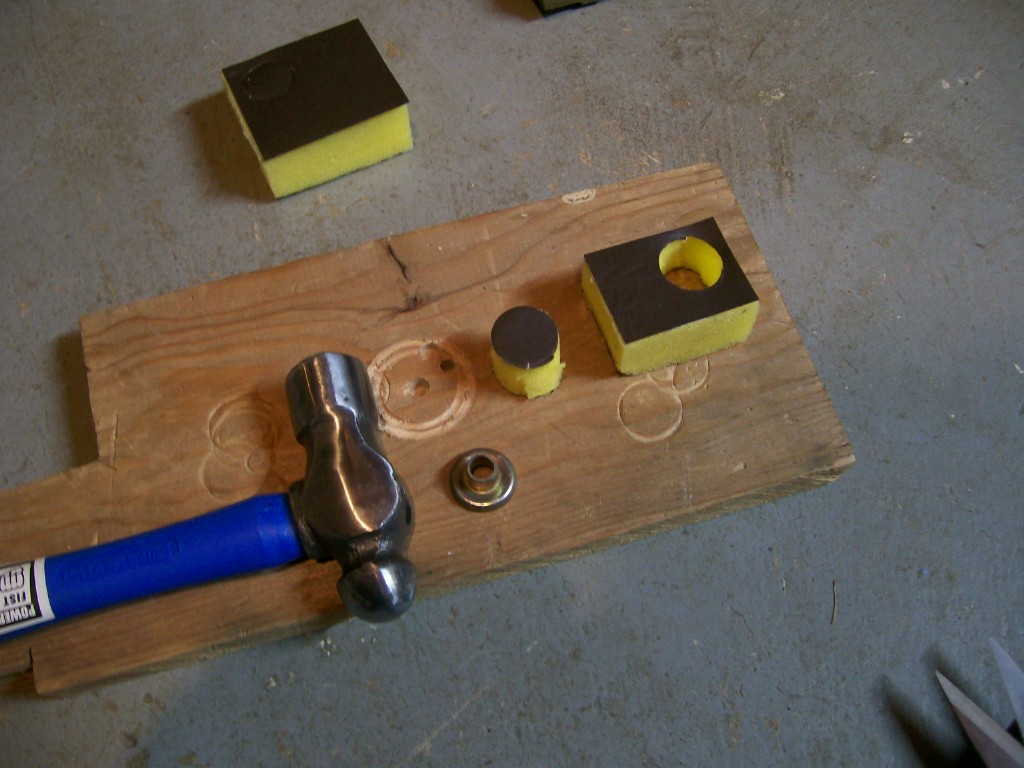
Use a leather-type hole punch to create the bolts holes. This is a tedious but necessary part of the job. I've marked the hole centres and shapes in the templates. Here's a trick that I just learned (once again, after the fact) that will make things go faster and easier: For your backing board, don't use the flat side of a board ('face grain'). Instead, do your punching against the end grain (I used an end-cutting from a piece of pine 2 x 4 held in my bench vise). Punching into the end grain produces a cleaner hole in the foam and it takes a lot less pounding to get the job done
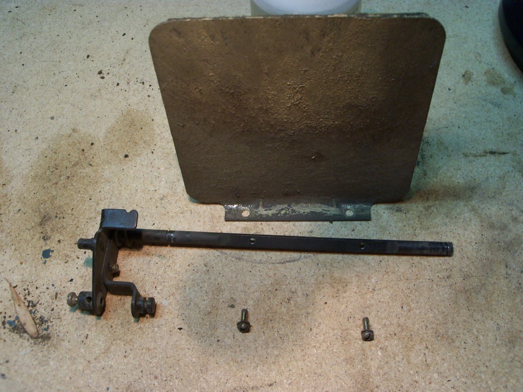
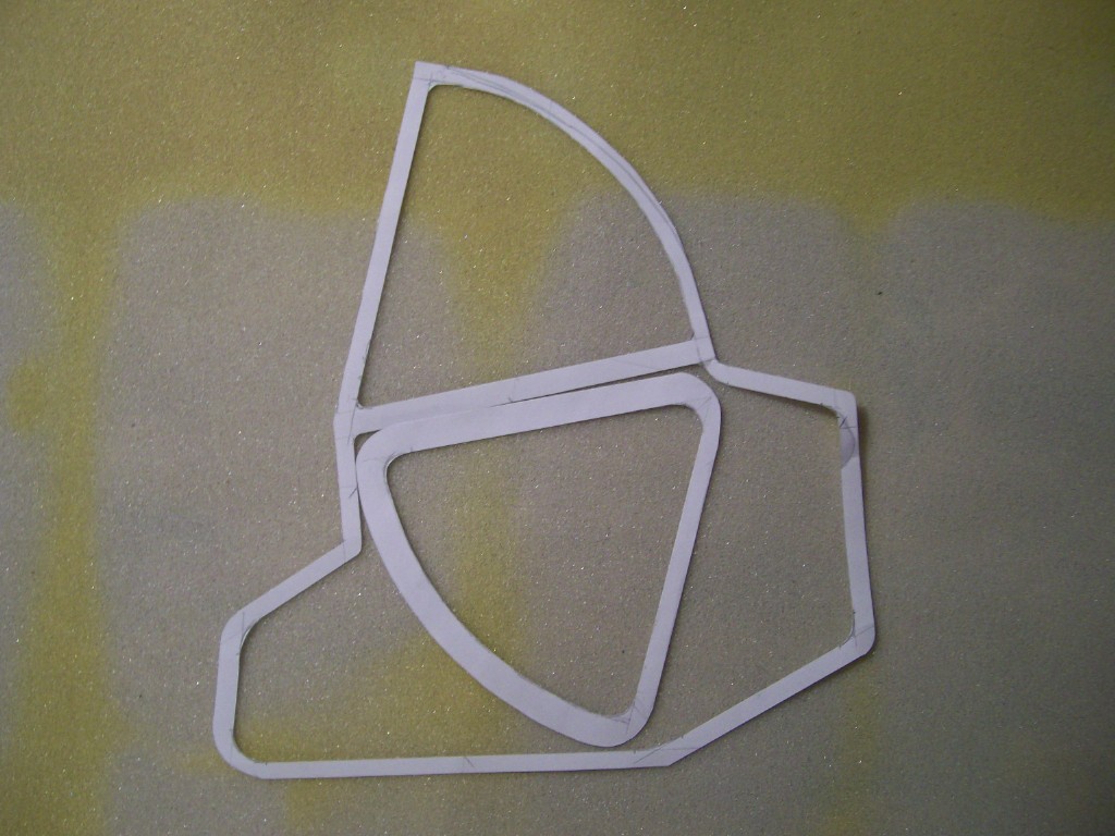
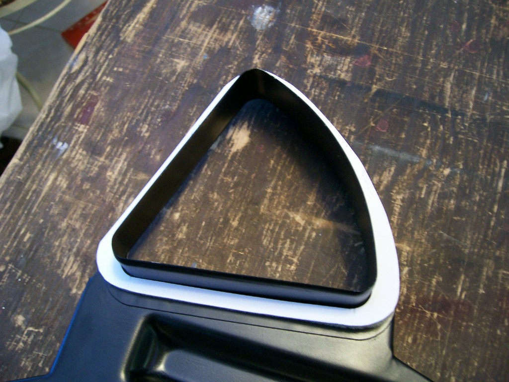
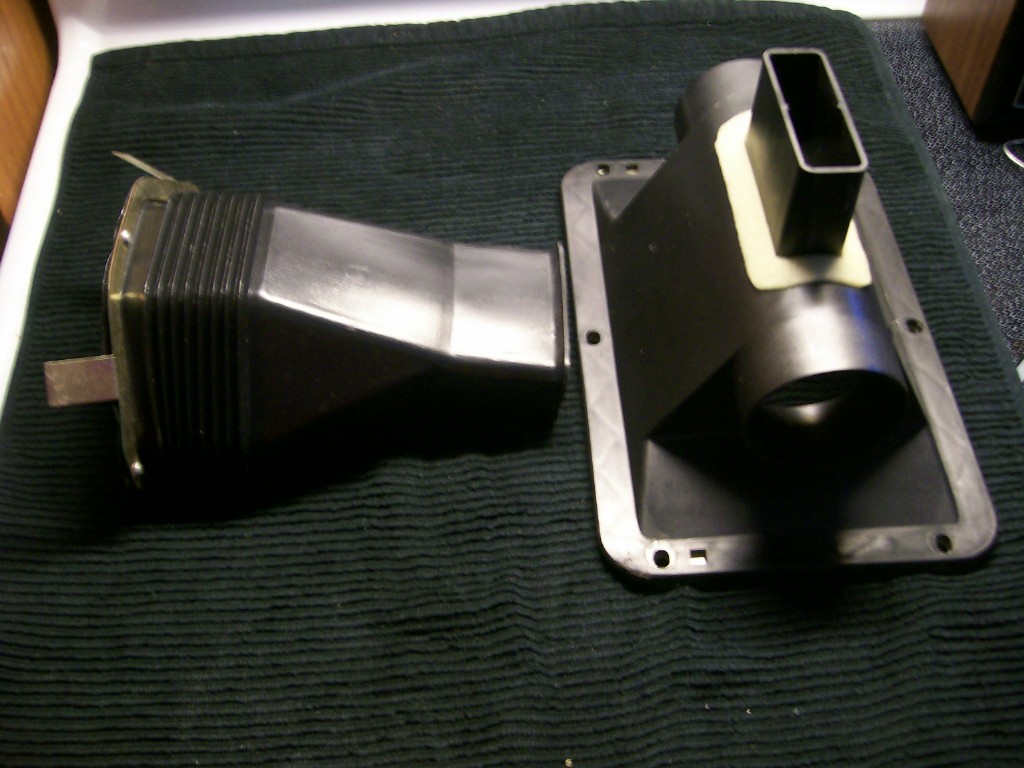
Special Gaskets #1 - Heater Box End Plate
Unfortunately, you're going to need to make your own template for these gaskets (there are two), because the ones I made were too big to fit on my computer scanner. They're relatively easy to make. Just tip the open end of the Heater Box onto a large sheet of tracing paper and use a pencil to make the outline. After you remove the box from the paper, you'll now need to draw cut lines for the inner and outer edges of the gasket. Do the outer cut line first. Draw it freehand so that it sits inboard of your traced line by about 1/16" - 3/64". Then draw the inner cut line (again, freehand) so that the width of the gasket is about ¼" all the way around.
Note that the factory gasket was actually applied around the inside lip of the end plate's joining flange. Good luck trying to replicate that approach with your forty-year-old housing a cover plate. It's easy enough to cut the gasket strip and glue in in place. However, trying to slide the end plate over the end of the heater box without destroying the gasket is another matter altogether (and maybe that's why Nissan changed the Heater Box design later on so that it split down the center and got rid of the removable end plate). My approach was to make gaskets that would form a butt seal. Once cut, I glued these onto the main housing, rather than the end plate. This may not be quite as air-tight as the factory's lip-seal approach, but I think it's going to be pretty close. Feel free to try the lip-seal strategy if you like. Just remember to put on your hair shirt before you try to re-install the end plate.
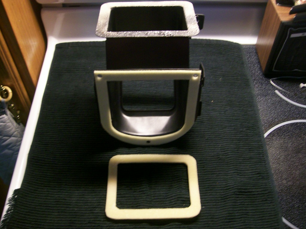
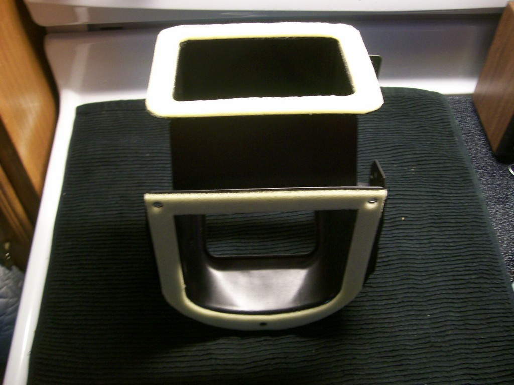
Special Gaskets #2 - Big Air Control Flaps
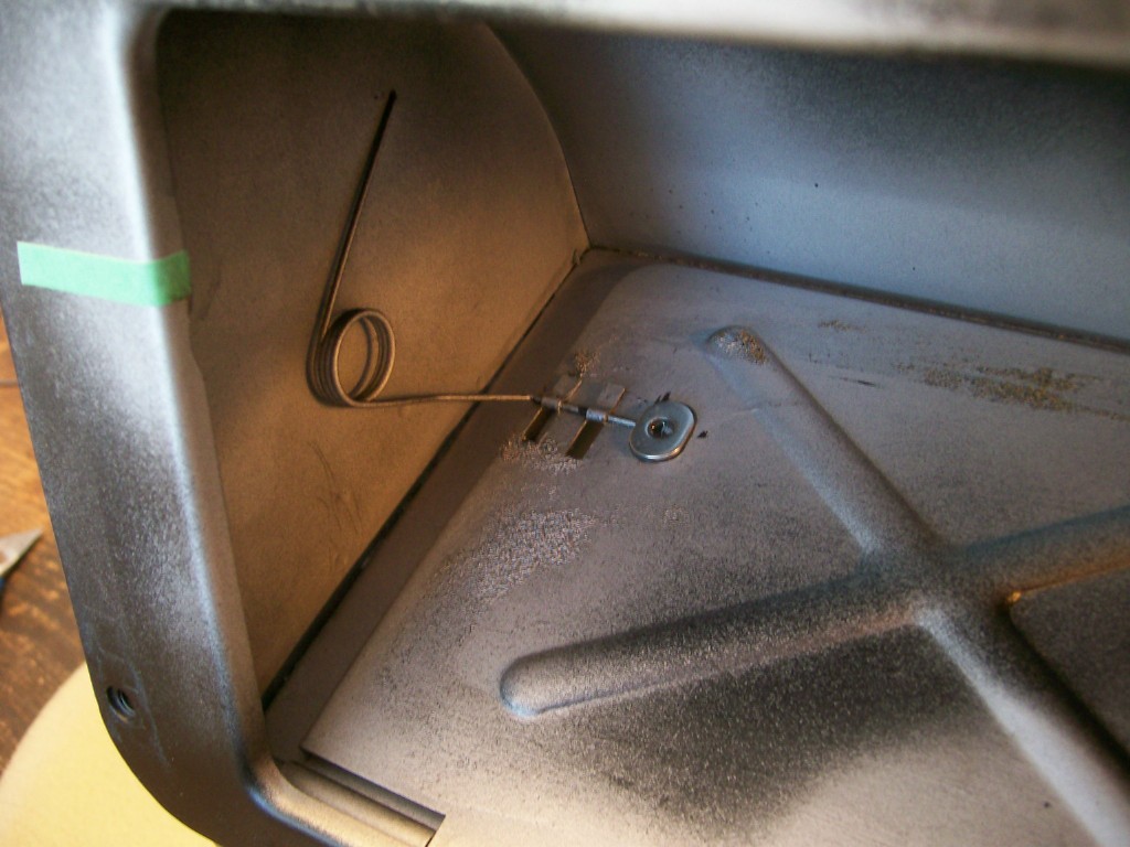
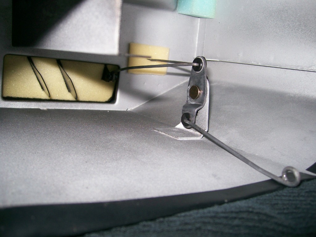
There are two big air control flaps used in the system: the first is the fresh air/recirc control flap (located inside the 'Air Intake Compartment' housing, upstream of the Blower); the second is the vent/defrost control flap (located at the outlet of the Heater Box housing). Each one is operated by one of the control levers on the centre stack fascia. Each flap uses an over-centre, hairpin-type spring to create a 'toggle' action as the flap is moved from one setting to the other. Each of the flaps are finished with a padded-vinyl skin, applied to both sides of the flap. When the car was new, the flaps seated with a nice, reassuring 'thunk'. Unfortunately, after the system gets to be 30 or 40 years old, the padded-vinyl skin begins to deteriorate and peel off, changing the 'thunk' to a 'clang'.
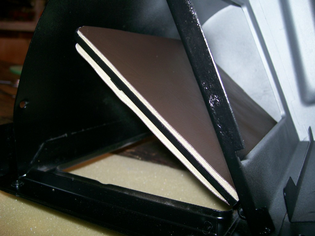
To re-create these vinyl-skinned flap liners, I recommend you use 1/4" dressmaker's foam (I ended up using two sheets of 1/8" foam glued together). Buy some thin upholstery vinyl while you're in the store (the flaps are invisible, so colour doesn't matter). Glue the vinyl to the foam (3M 80888 spray adhesive recommended) first, then cut the flap liners to shape. You need to be careful when positioning these liners, so that they seat properly around the entire periphery of the flange and don't foul the return spring that's located on one side. 'Align twice, glue once'.
It's not terribly difficult to take the flap assembly apart. This will let you make a better/easier job of cleaning the flap surfaces and it will also let you clean and lube the shaft pivot surfaces.
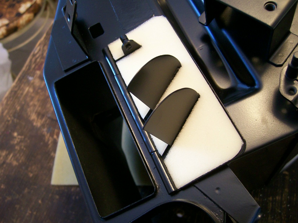
BTW, the little flaps that control the floor vents also have liners fitted. Again, they serve as both an air seal and a cushion (so that the flaps don't clang shut and then rattle and squeak). The foam to use in this location is either 1/8" open-cell foam or 1/16" closed-cell neoprene sheet. I used the former. These gaskets are hard to cut and hard to fit. They have to be cut in order to fit over the directional vanes, etc. and that makes them floppy and hard to handle. At the same time, they need to fit properly or else they won't seat against the adjoining flange on the Heater Box outlet.
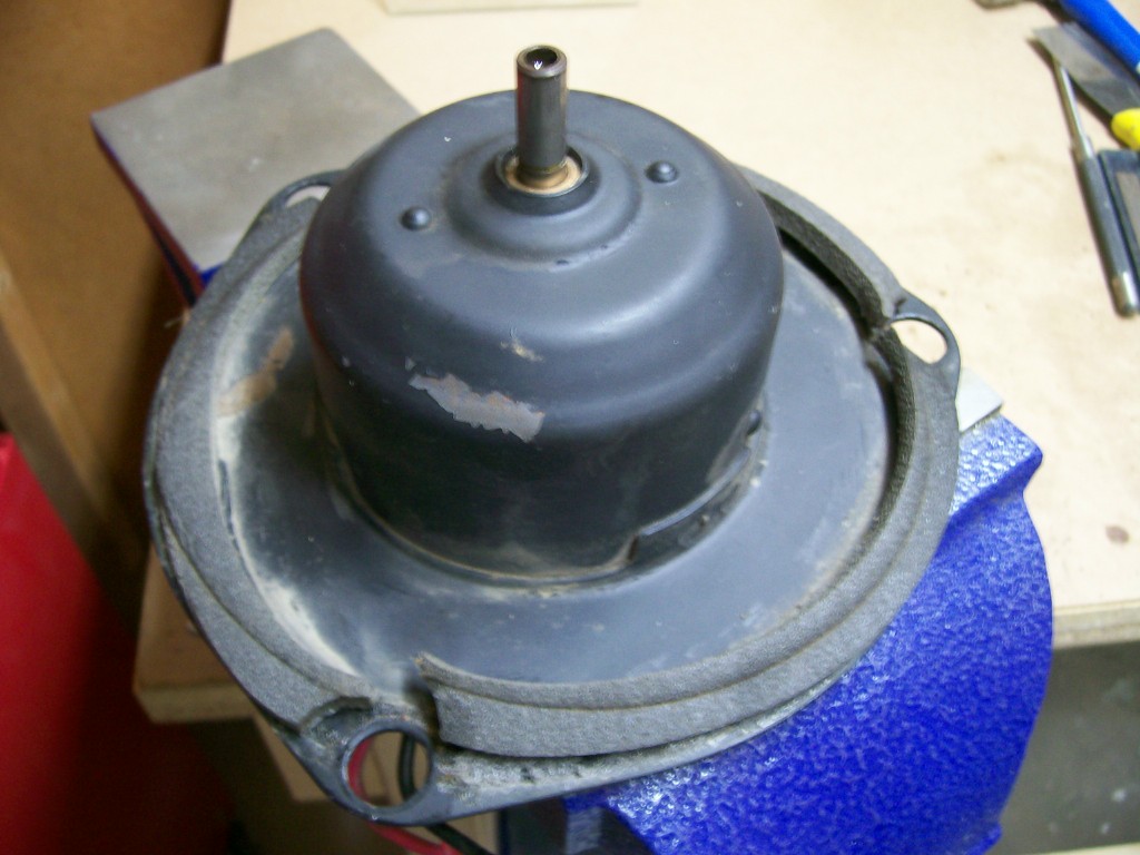
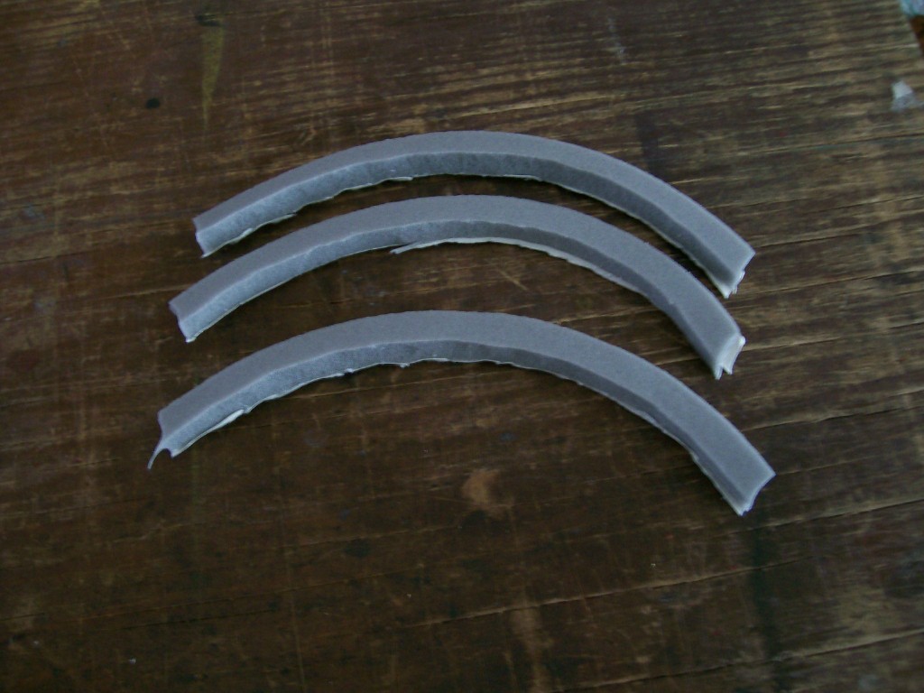
Special Gaskets #3 - Blower Motor-to-Blower Housing
In this case, the gasket(s) function as both an air seal and as a vibration isolator. While the gasket as it came from the factory looks like it was cut as one piece, I found the areas around the three bolt holes to be too narrow to permit punching out the holes without severing the gasket. For that reason, I cut mine as three identical pieces, each representing one-third of the whole. I think it's a good enough seal.
Because this gasket also has to provide a cushioning mounting surface for the Blower Motor/Impeller assembly, I used yet another type of foam for the purpose - in this case, it's 3/16" closed-cell, medium-density foam. My feeling is that the 3/16" neoprene sheet might, once again, be a bit too hard (durometer) for the application. My foam had one-sided adhesive with a strip-off protective sheet, so the three pieces were relatively easy to place and secure accurately.
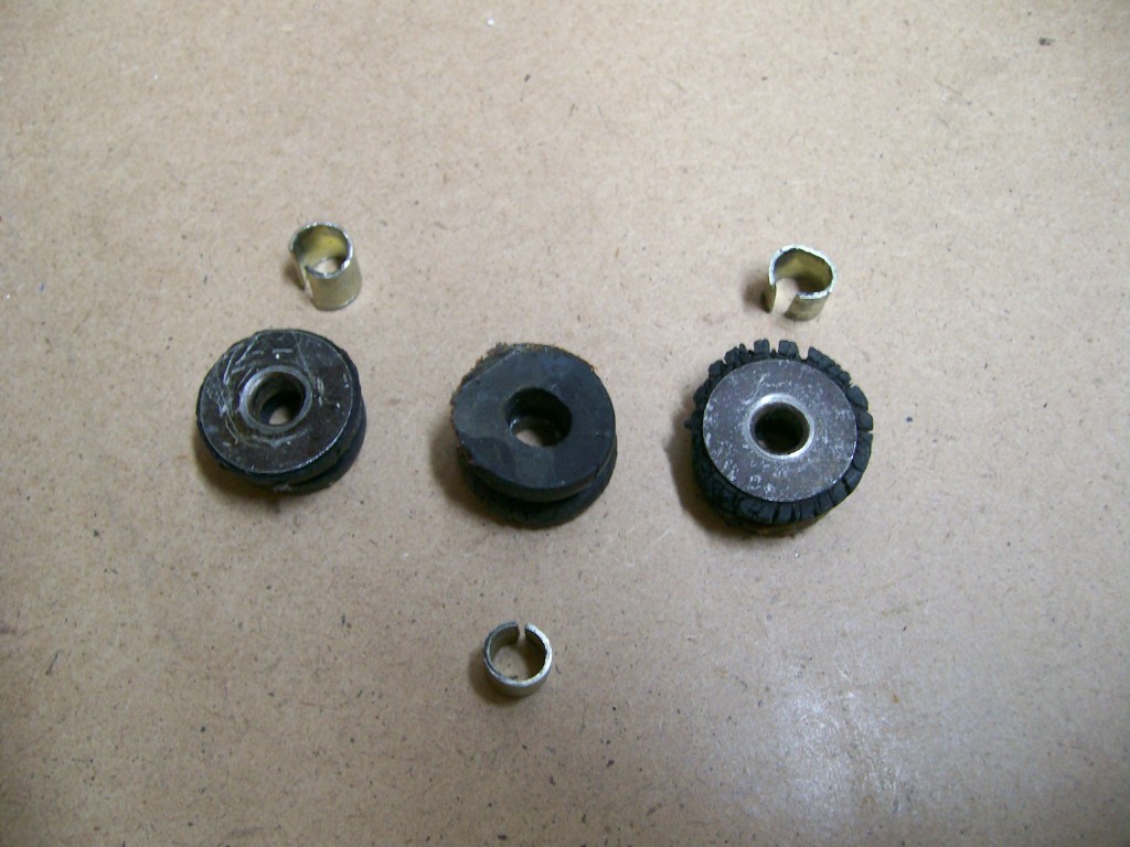
If your unit with like mine was, you'll need to replace the four rubber grommets that are used in the Motor/Impeller mounting plate. These are fitted as two pairs - one round pair and one oblong pair. They all have suitably shaped press-in metal liners. Accurate reproduction items are now available from a speciality supplier. The original grommets will probably be hard as a rock and won't be serving their purpose properly. None of the 'rubber softening' formulations that I've tried are even a tiny bit effective (I'd call them 'preservatives' rather than 'softeners').
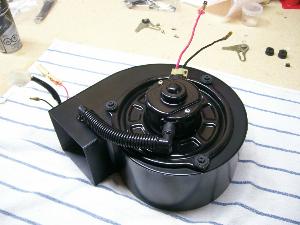
The last picture here shows my completed Blower assembly. It's been retrofitted with a Honda Civic motor and impeller (more output, less noise, less current draw), complete with a customer-built duct to replicated the motor brush cooling system used on the original Honda setup. I've re-painted everything in satin black to make it look pretty. Now it just needs to have the Nissan wiring connectors added in place of the Honda items. I'm still toying with the idea of adding an 'intermittent' setting for the controls.
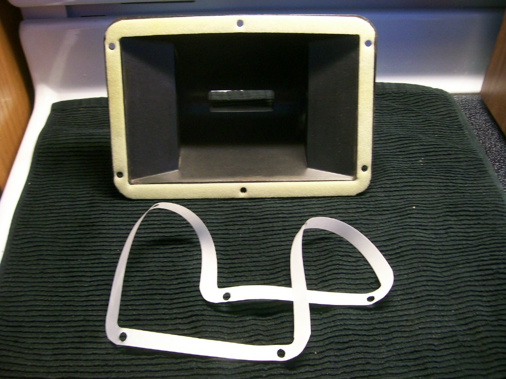
Special Gaskets #4 - Centre Front Ventilator Duct
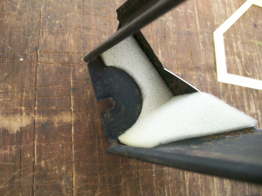
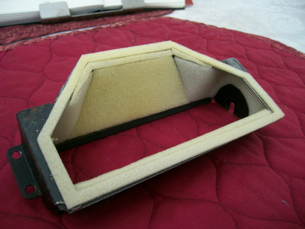
Here's another place where the foam isn't actually acting as a gasket. In this case, the factory lined the inside surfaces of the metal duct outlet with thin, open-cell foam in order to reduce airflow noise. I can't say how well this actually works (you'd need to try 'with' and 'without' to really know). However, the set of templates includes the pieces needed to re-create this liner. It's finicky work to get this done right. You'll need to use 1/8" dressmaker's (open-cell) foam for it to work (the closed-cell neoprene foam won't offer any quietening effect). Excessive gaps or steps between the foam pieces make un-do the intended purpose of the lining, so you need to be careful here. Also, poor cutting or gluing could cause the foam to foul the rotating, chromed directional-vane piece.
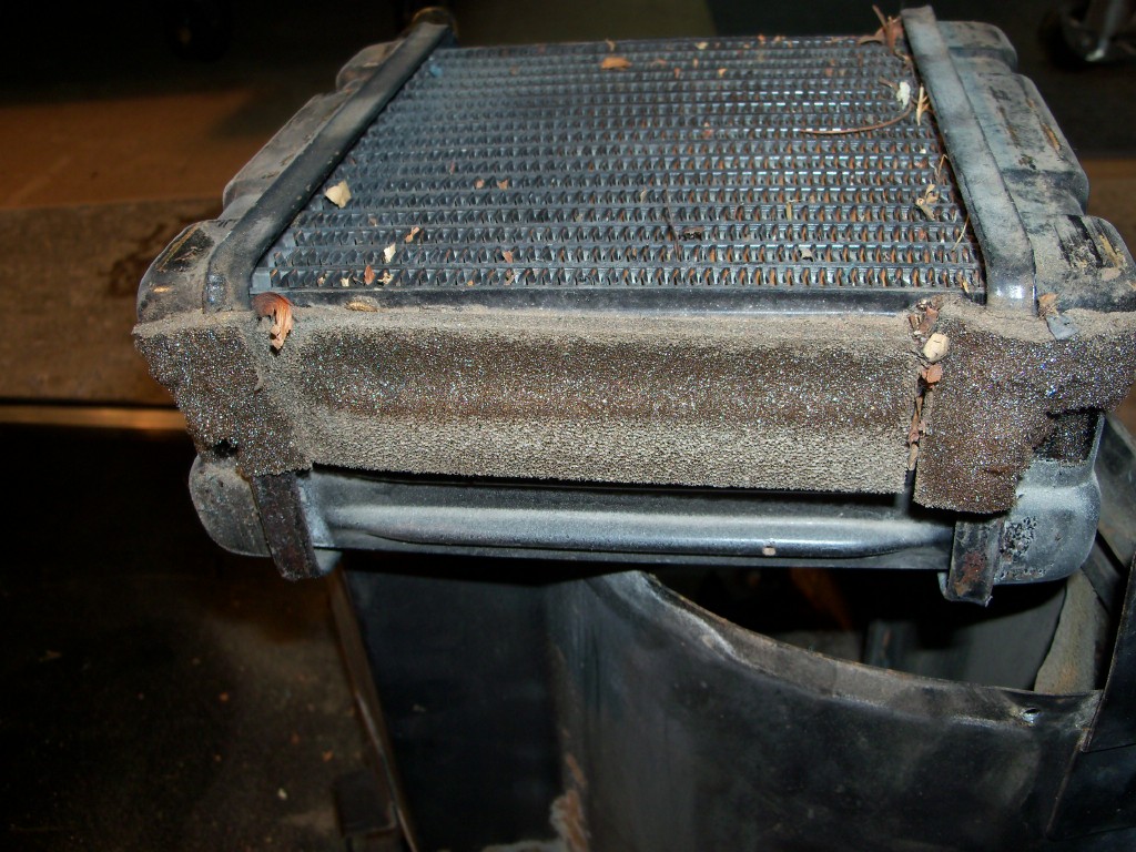
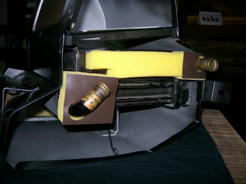
Special Gaskets #5 - Heater Core Pads
Most of these aren't really gaskets, of course. They're pads glued to the heater core to keep it from generating squeaks and rattles after it's slid into position inside the Heater Box. There are end pads applied to both the left and right header tanks. The factory put a long central pad along the centre part of the left (driver's side) header tank. I don't think it's necessary because the header tank is indented there and there's no potential for metal-to-metal content. I just used the little pads located at either end of the tank. I glued these to the wall of the Heater Box, rather than gluing them to the header tank.
There are also vinyl skinned pads that act as sleeves around the Heater core's supply and return pipes. These actually do function as gaskets, hence the vinyl skin (which acts as a seal against the removable end plate of the Heater Box).
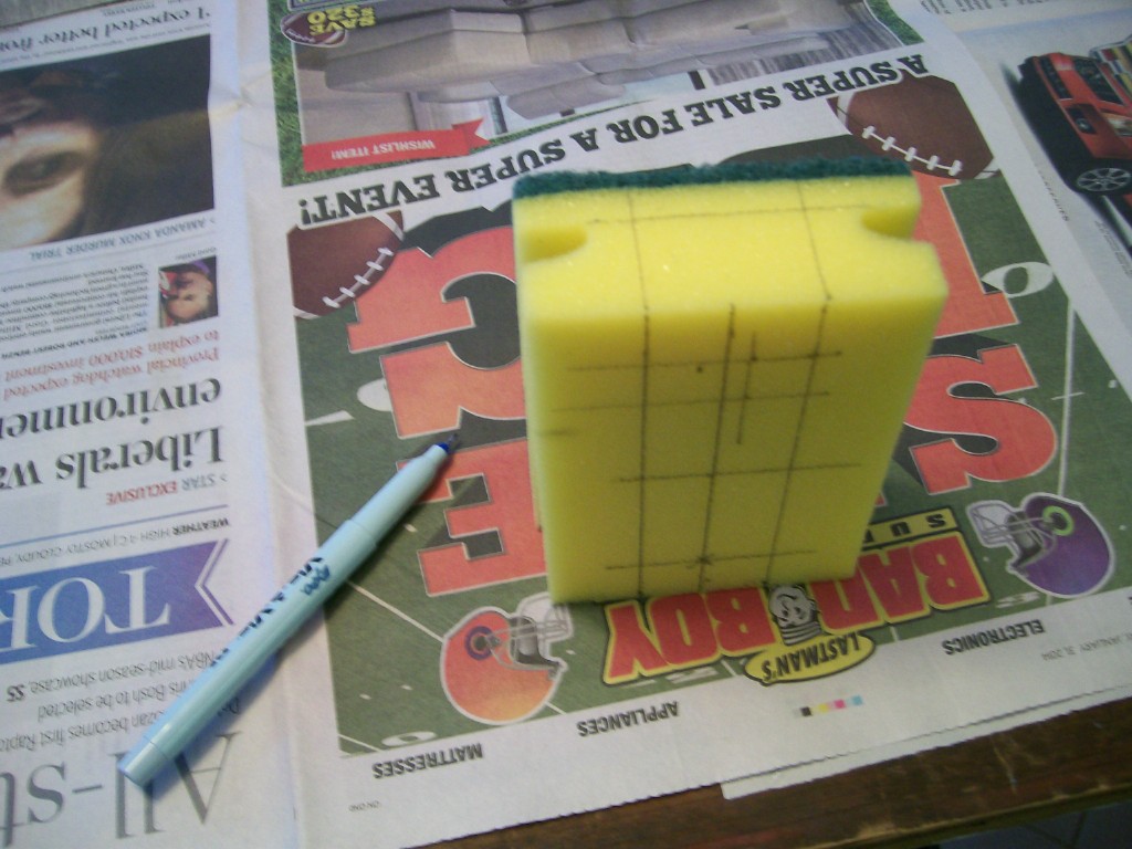
In all cases here, the factory used soft, open-cell foam. The re-create this, I found some inexpensive kitchen sponges purchased from the local Dollar Store that were about right. These had to be cut to shape. I marked off the cut lines with a pen and then used a hooked razor knife to make the cuts.
The vinyl skin for the supply/return line sleeves is best glued to the foam after you've done your cutting (the thick foam squirms a lot when it's being cut, and it's hard to cleanly cut through both the thick foam and the vinyl in one shot). I did, however, make the holes after the vinyl had been glued in place. I didn't have a ready-made leather punch big enough to make these rather large holes, so I made one from a lamp fixture found in my odds-and-ends drawer (the cutting edge was made with a file after I'd chucked the piece into my drill press). Here's a place where my new-found knowledge about punching into the end grain of the wood backing piece would have made for a better and easier job (notice the blunt impressions made in the wood after pounding against the face grain).
General Suggestions
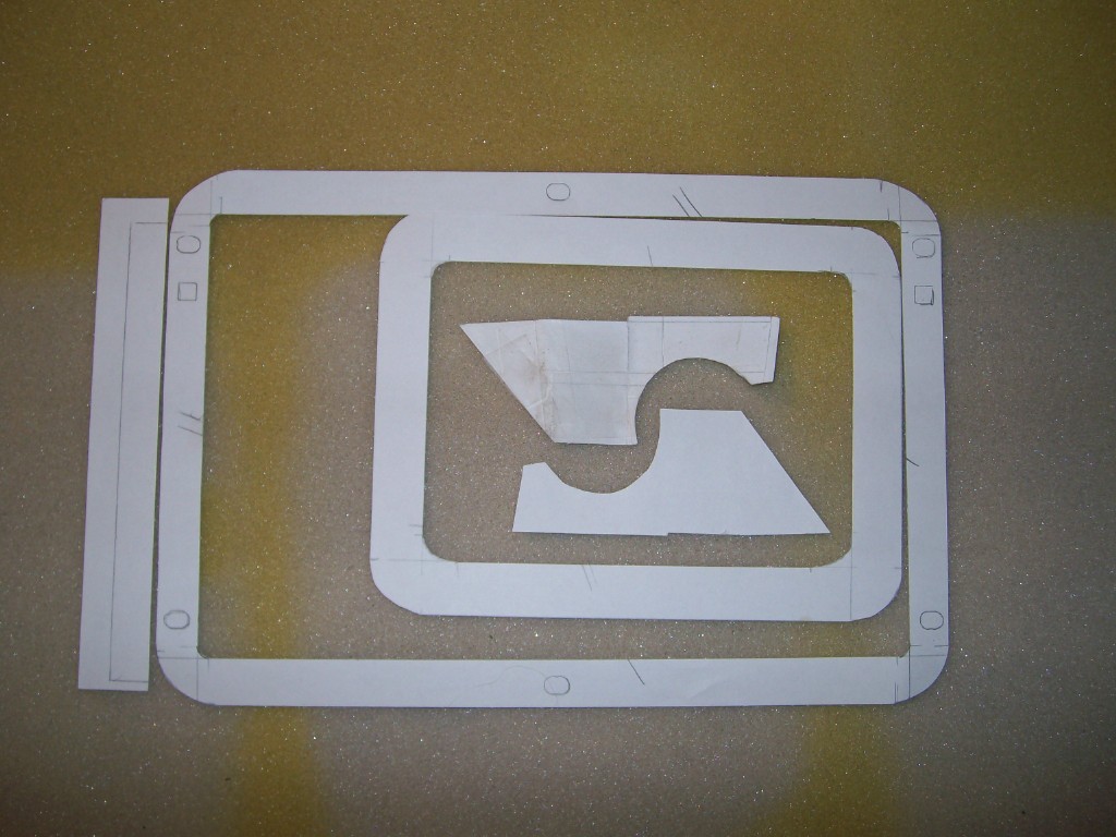
Depending on how much wastage you can tolerate, it will be more economical if you nest the gasket templates into groups, so as to make maximum use of each 8-1/2 x 11" sheet of neoprene. See photos for illustrations of how I did this.
I've found that this closed-cell neoprene responds remarkably well to cyanoacrylate glue ('super glue'). The big gaskets for the Heater Box End Plate can are too big to be cut as single pieces from an 8-1/2 x 11" sheet, so they have to each be made from 2 pieces joined together. You can - if you want - glue the pieces together with butt joins before installing as a single piece on the housing. Or, you can just glue them in place one after the other (easier). Try to keep the gaps at the cut ends as small as possible.
As I mentioned at the outset, this is a long and tedious job. The picture of the mess I had left behind tells part of the story. Having my templates available will certainly remove a lot of the challenges.
For the locations where all that's needed is a joint seal, you can - arguably - get the same functional result by just using adhesive-backed foam strip purchased in a roll from the hardware store. You could even try using silicone caulking as a replacement for cut-foam gaskets. Neither of these approaches will help you for the flaps, the acoustic lining, and the Heater Core pads and sleeves. You'll have to decide what works best to meet your personal objectives for your project.
Namerow
Burlington, Ontario
May 2016


Recommended Comments
Create an account or sign in to comment
You need to be a member in order to leave a comment
Create an account
Sign up for a new account in our community. It's easy!
Register a new accountSign in
Already have an account? Sign in here.
Sign In Now