.JPG.cfcada9cf1c1b502df3f5f2f2ca3ff36.JPG)

SteveJ
Community Member
-
Joined
-
Last visited
Everything posted by SteveJ
-
@Captain Obvious, I remember we discussed this some after I posted the video of the fuel gauge bench test. Indirectly you can see the voltage regulator in that gauge start by watching the ammeter on the power supply I was using. When it was cold, the current was high, and then as it reached equilibrium you could see the current fluctuating as the VR pulsed.
-
Thank you. I didn't remember they had the same VR.
-
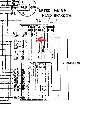
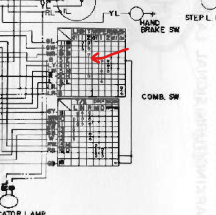
First, I misread the wiring diagram. It's the blue wire, not the green/white that provides power. I'm not sure what you're looking at to say C6. Page BE-32 shows the blue wire going through C5 and over to the 6 pin connector for the gauge. The ground wire goes through C1. I hope that helps to clear things up for you. Make sure you look at BE-32 and ask questions on it if you need to.
-
The headlight circuit wiring changed some time during 71 or between 71 and 72, I believe. The original circuit had the headlight switch completing the path to ground from the high/low beam switch as shown in the 70 and 71 FSM. In 72, the headlight switch controlled the wire going to the fuse box. (white/red to red wires) The high/low beam switch connected to the ground wire instead of going through the headlight switch. This later design was used for the rest of the S30 run. The change in the 260Z on is the type connector used at the headlights. I periodically search to see if anybody has found a source, but I haven't had any luck so far. Dave mentioned the wiring change in the headlight circuit to me many years ago, and I dug through the wiring diagrams to understand what he was saying.
-
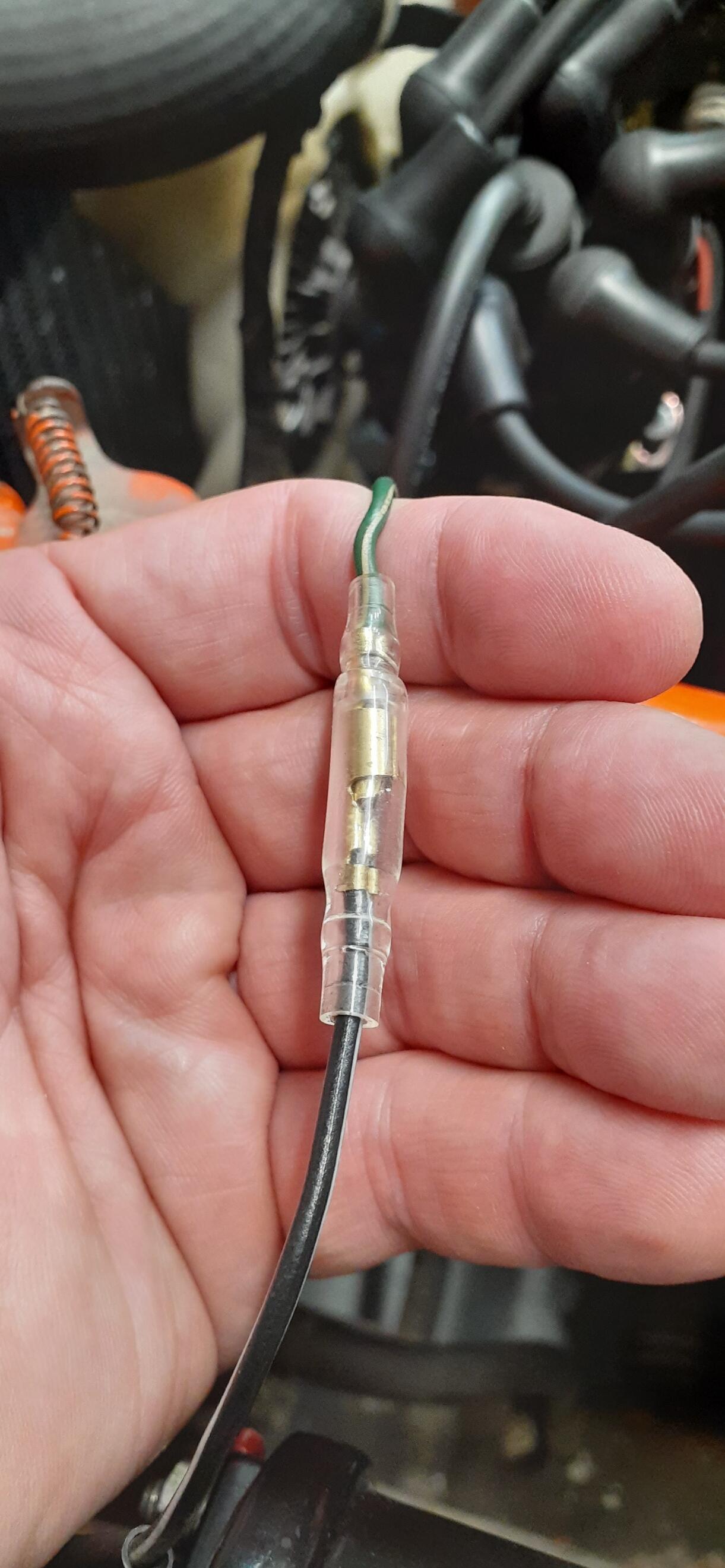
The meters have a common power source and a common ground. Note: I removed removed the image from the post since I tagged the wrong wire for the positive side of the circuit. I should have tagged the blue wire going into the 6 pin connector. The black is the ground for the gauges. Inspect the pins on the male and female connectors, looking for loose connections and corrosion. Also look for damage on the wiring harness on the back of the gauge and on the dash harness. After you remove the gauge, you may also want to start the car and measure voltage between the green/white and black wires on the connector for the gauge.
-
I hope you used fuses smaller than 30 A. That high of a rating won't protect the wiring adequately in the event of a short circuit. Just to be specific, this diagram only works for the early 240Zs where the headlight switch completed the path to ground. The later cars would have to be wired differently than this.
-
Charging problems with two alternators first points to the voltage regulator, especially since you didn't say whether or not you changed it. Keep in mind that if the voltage regulator is original, it is adjustable. The EE section of the FSM has the procedure. In addition to the link @kickstand80provided, you can download the FSM from here: The EE section is available, but unfortunately some other sections are not. (This applies to either download site.) If the voltage regulator is not an OEM part, it's probably time to replace it. You should test the alternator first, as was suggested. It looks like MSA has the best price for a VR, https://www.thezstore.com/page/TZS/PROD/12-4083. You may want to bite the bullet and order it today so it ships before they are closed for the long weekend.
-
What year 280Z?
-
I bought a 4-speed shift knob off ebay, and the threads weren't right. I ended up reaming out the hole and using a threaded insert.
-
No, it's not a loose fit. You press it on.
-
-
No, it clamps onto the ridge around the doorframe, just like the stock weatherstrip.
-
I bought some generic door weatherstrip from Amazon. https://www.amazon.com/gp/product/B00NELWRJ4 I believe it worked well, and it installed easily. I go into more detail in my thread on waking up my 73.
-
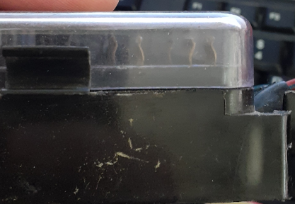
I would be shocked if it did. There is only about 3 or 4 mm clearance above the fuses in the fusebox.
-
Yep, that's what I saw, too.
-
No, but then again, I didn't come across as an obtuse fool, and I'm willing to re-think things after I'm proven wrong.
-
It's better to keep as much of the original wires intact, but it's easy to "kill" the GW and BW wires in the engine bay, I outlined that earlier. However, Duffy was hindered by the evaporator on the aftermarket AC. The wiring suggestions I gave a couple of comments prior to this one would be easy to implement.
-
-
You don't need the diodes. What I gave you was a very simple way to wire. You said you aren't using the GW wire for the tach, so all you would need to do is land the GW and BW wire at the same place in the engine bay or replace the terminals on them now for a male/female bullet. Why do you want to do 10 times more work?
-
In the stock wiring, the GW wire has power with the key in Start and goes over to the tachometer. This wire also branches over to the ballast resistor. The BW wire branches out to the engine bay to the other side of the ballast resistor. The other branch of the BW wire goes to the center stack where it splits again. One branch goes to the fuse box and the other goes to a 2 pin T-shaped connector. You could get a connector from Vintage Connections that will let you plug an inline fuse into the circuit and go out to the pink wire on the Haltech. http://www.vintageconnections.com/Products/Detail/79 You could also get a single pin connector to attach the inline fuse to the pink wire: http://www.vintageconnections.com/Products/Detail/78 The only caveat is that you can't have the GW wire going to the tachometer connector anymore.
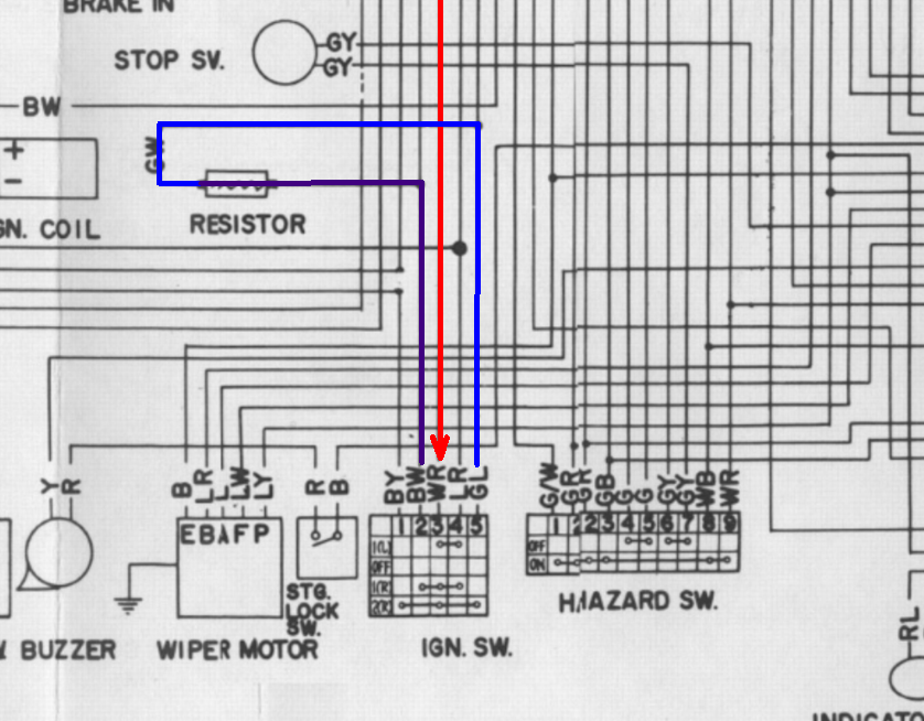
-
Probably the easiest way to ensure you have power at start and on is to jumper the BW from the ignition switch to the GW at the ballast resistor. You won't backfeed the circuit for the starter solenoid. After watching Duffy's video, I ran a test on my 73. I disconnected the solenoid wire and took apart the connection for the BW and GW wires under the hood that I did put together to jumper out the ballast. (BW cannot backfeed the GW wire.) I put the turn signal into a right turn and put the key in start. The turn signal flashed, meaning in my 73 with an original switch (AFAIK) supplies power to the BW wire in start and on.
-
I used a clip lead and remote starter. https://www.amazon.com/INNOVA-3630-Remote-Starter-Switch/dp/B000EVU8MK Clip one end of the clip lead to the negative of the battery and the other to the body of the horn. Clip one end of the remote starter to the positive of the battery and the other end to the terminal on the horn. I suggest holding the horn so the positive terminal cannot touch the body of the car and short. Press the button on the remote starter.
-
And I have already demonstrated that your flawed design won't work and should be consigned to the trash heap. But what would I know? I only work with these kinds of circuits for a living.
-
You may want to check out Vintage Dashes or search for Hung Vu on Facebook. https://www.classiczcars.com/forums/topic/67730-reproduction-240-dash/#comment-643729
-
It's not exactly plug and play. I just don't like cutting factory wires if I don't have to. One could back out the BW wires out of C-2 and C-3 and put them into smaller AMP connectors. The dash harness side would go to the key source on the Pertronix. The BW on the engine harness side would go to the BW on the Pertronix. That would save running a wire all of the way from the Pertronix in the passenger footwell to the coil.