.JPG.cfcada9cf1c1b502df3f5f2f2ca3ff36.JPG)

SteveJ
Community Member
-
Joined
-
Last visited
Everything posted by SteveJ
-
A friend installed a Pertronix Ignitor I into his 240Z, and he contacted me for help since he could cruise fine at low RPM, but whenever he tried to get on the gas, it would stumble and cough. He thought it might be a coil impedance issue so he tried various coils but kept having the same issue (and sometimes even worse performance). Since he has been wrenching on Z cars since the mid 80s, I figured he had gone down the wrong rabbit hole at some point. I loaded up the rescue wagon and headed over to his place. The first thing I did was connect an oscilloscope to see if I could pick up an obvious miss. The scope left me with the impression that something wasn't happening right as higher RPMs. (I might recreate his problem on my 240Z and see if the scope shows the same thing. If it does, I'll make a video to help people with diagnostics.) I looked at the resistance to chassis ground at the distributor. The resistance was nearly zero, so it wasn't a grounding problem. From some old threads here, I thought the vacuum advance might be an issue. Unfortunately his hand pump would let me pump up enough vacuum to check, so that was tabled. Next was inspecting the distributor cap. The contacts were clean as was the rotor. So I moved to inspecting the posts where the wires land. The wire on the center post wasn't seated far enough down, so I pushed that in. Then I pulled off each wire one by one, starting with #3 and working clockwise. It was good, #5 was good, #1 was good, #4 was good, but #2 was not. The boot was almost off the wire. There was no way it was getting a good spark. I positioned the wire properly in the boot and re-seated it. Then I checked #6. It was good. I looked at the scope again. It looked better, but I didn't shoot video. After my friend fixed a fuel leak at the banjo fitting on the rear carb, (The fitting wouldn't seal, so he replaced it.) he took it for a spin. He said there was no hesitation, and it pulled hard past 5,500 RPM. The moral of the story is that when you can't figure out what's wrong, step back and go over everything from the beginning. Sometimes you have to eliminate each and every variable until you have the solution. I love getting another Z back on the road.
-
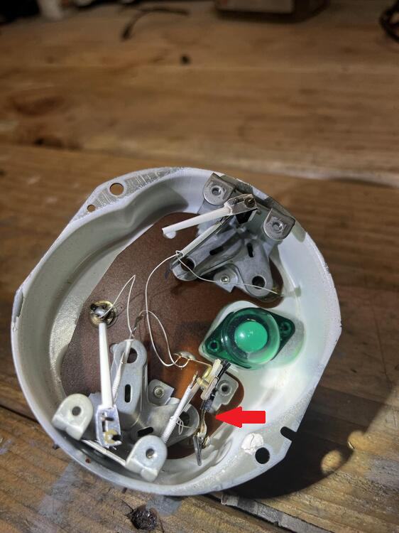
The voltage regulator is the part on the right. See the red arrow. If it's working properly, you should see it opening and closing rapidly, like you saw the ammeter needle moving in my video. As far as fix it, you would have to re-wind the coil with that fine insulated wire.
-
Reach out to Alan Poindexter at https://vintagezparts.com/ He focuses a lot on Z31s.
-
There are places that might be able to repair/replace the voltage regulator. https://www.google.com/search?q=automotive+gauge+restoration&sxsrf=ALiCzsa7dCxxAJmczzDprB3YHBA44vbQSw%3A1663426703398&ei=j-AlY7jrF7-kqtsPhJys0Ag&oq=automotive+gauge+res&gs_lcp=Cgdnd3Mtd2l6EAEYADIFCAAQgAQyBggAEB4QFjIGCAAQHhAWMgYIABAeEBYyBggAEB4QFjIGCAAQHhAWMgYIABAeEBYyBQgAEIYDMgUIABCGAzIFCAAQhgM6DQgAEEcQ1gQQsAMQyQM6CggAEEcQ1gQQsAM6BAgAEEM6CAgAEIAEEMkDSgQIQRgASgQIRhgAUPoJWL8MYNUcaAJwAXgBgAHlAYgB0gOSAQUwLjIuMZgBAKABAcgBCMABAQ&sclient=gws-wiz ebay offerings are probably cheaper. https://www.ebay.com/sch/i.html?_from=R40&_trksid=p2380057.m570.l1313&_nkw=280Z+temperature+gauge&_sacat=0 If you go the latter route, save your gauge. Someone may want it to have one to restore later.
-
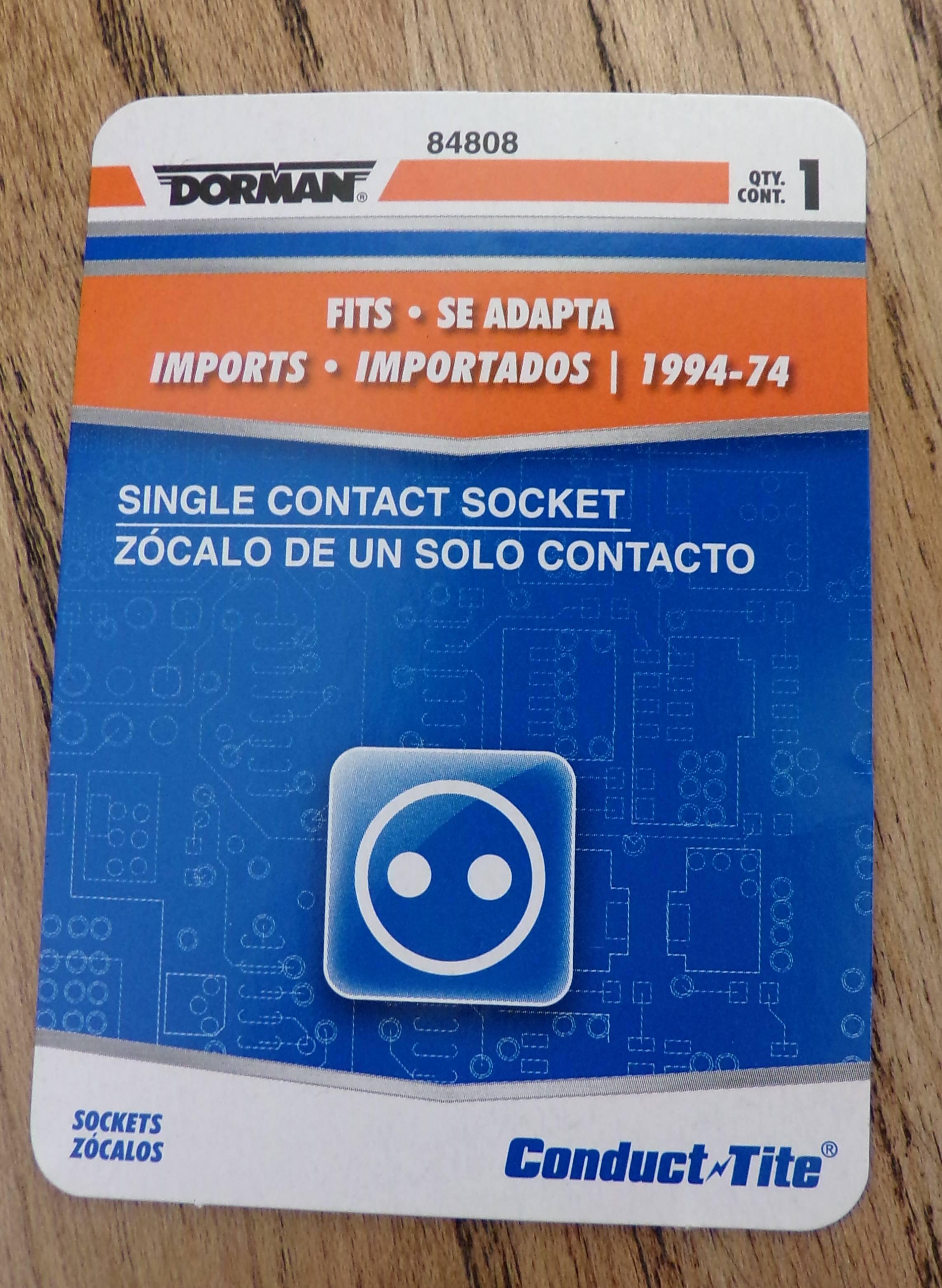
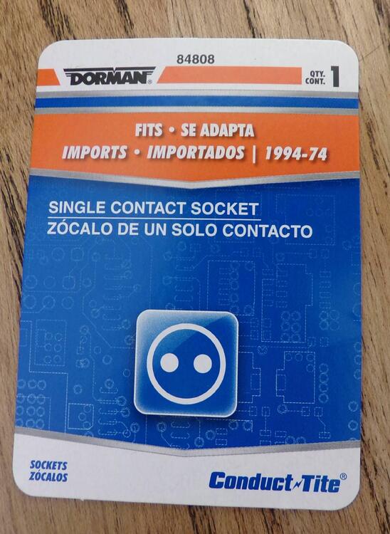
In my never ending quest to find parts that no one seems to be looking for, I finally found what seems to be a good replacement for the single filament (1156 style) bulb sockets for the tail lights and reverse lights. The Dorman 84808 fits snugly in the tail light housing. You can find them on Amazon and Rockauto. I'm going to get a Dorman S847 to see if it's a suitable replacement for the 1157 sockets.
-
Probably. I'm starting to see a pattern.
-
-
No fuss, no muss, no unsightly build-up. We are glad your Z is operating normally. I would not be surprised if it drove better now.
-
FB is good for posting pictures and getting lots of bad advice that buries the responses from the few knowledgeable people.
-
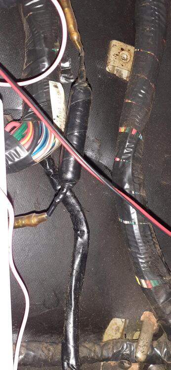
Also, here is a picture of the resistor in the passenger footwell of my 260Z. As @Zed Head said, it's taped up like a mummy. It might have different connectors in the 280Z, but this should give you an idea of what you should be looking for. It will probably be below where the engine wiring harness comes through the firewall.
-
First he needs to take out the TIU and 10K resistor to see if he has a problem. I would not be surprised if getting rid of those (along with ensuring the stock resistor is in place) fixes his problem.
-
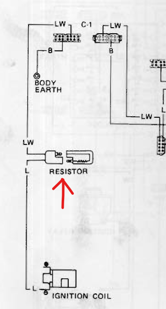
Just to complete the explanation, the TIU does the same thing as the "matchbox" module on the ZX distributor. Several years ago, a friend did a ZX distributor conversion on a 260Z and brought the car to me because it wasn't running right. The first question I had was, "Did you disconnect the TIU?" After he unplugged it, the car ran like a scalded dog. Verify that the stock resistor is still in place. It should reside in the passenger footwell and plug into the wiring harness.
-
So if you converted to a ZX distributor, why did you leave the TIU in place? It should go bye-bye. Also why did you solder in a 10K ohm resistor? The value should be 2.2K ohm if I remember correctly, though on a Google search @Zed Head gave a value of 2.3k on another thread. Double check the FSM. I know it has the value.
-
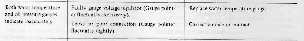
Here's straight from the FSM troubleshooting guide:

-
If they are both moving all back and forth, I would think it would be the voltage regulator.
-
Unfortunately, it seems to be true. The message said they stopped taking new orders as of 9/9.
-
Did you remove the TIU from the car? Do you still have the resistor (not the ballast resistor) in between the tach and the ignition circuit?
-
I read on Zcar.com that Z Car Source closed. I called their number, and the outgoing message confirmed it. 😞
-
What? You didn't use a 4 pole double throw switch? That would have been even faster to switch over. 😉 Nice wiring.
-
It is interesting that in looking at the coupe vs 2+2 part numbers for the windshield page in the parts catalog, only the seal number is different. Maybe someone like @zspert might know.
-
Nice. Take a picture of the connector that the sockets go to. Since it has lamp sockets, it's most likely just a matter of modifying the connector at the steering column, running the wire in the dash harness and body harness, and maybe changing the connectors at the taillights to work with the modifications. As I said before, since the harnesses are not likely in the car, the wire can be run and wrapped into the harnesses. No cutting, no slashing, no ring around the collar.
-
Okay, so there is one place in the taillight harness you may have to cut wires unless you can source bulb sockets that work in the taillight sockets. (I just ordered a likely candidate, and I'll provide an update when I get my grubby paws on it.) Anyway, since the wiring harnesses are out, it wouldn't be a big deal to add a wire to the harness and wrap it to protect the wire. I've attached an example of how to do it on a 72. Turn Signal Modification for JDM Taillights.pdf
-
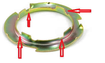
I'm not sure where it might be, but it's not too difficult. You will need to get the car high enough to get under the back. If that means jackstands, I suggest you drain the tank as much as possible first. Otherwise, you'll have fuel spilling out. I advise you to get a replacement lock ring and o-ring before you attempt to do this. If the lock ring gets warped, it won't seal. The lock ring has 4 tabs on it. I have arrows by where you need to turn it to remove the ring. Remove the wires from the sending unit Some people will place a screwdriver against one of the tabs and strike the end of the screwdriver to turn the ring. If you are worried about sparks, you may want to use a brass drift instead. I fabricated my own tool out of angle iron to turn the ring. You could also carve notches for the tabs in a piece of 2 inch PVC to turn it, though the height of the tool has to be small to fit unless you're dropping the tank. Pull the ring off. Remove the sending unit and o-ring. Re-installation Check the ring for flatness. If it is not flat, replace it. Put the new o-ring on the sending unit Thread the float though the opening in the tank and line up the sending unit with the locating tab on the tank. Holding the sending unit so that it stays aligned with the locating tab, put the locking ring on, and turn the ring using the tabs until it locks into place.
-
There's ALWAYS a way around cutting, but it can be a challenge.
-
The ZX went from a box bolted to the passenger side firewall (Transistor Ignition Unit or TIU) down to a small module on the side of the distributor. If your distributor and TIU are in good shape, you won't see any performance difference. Also, ZX distributors are getting rare. If the TIU dies, look into converting to an HEI with your existing distributor. I believe @EuroDat did a nice write up on doing that many years ago.