.JPG.cfcada9cf1c1b502df3f5f2f2ca3ff36.JPG)

SteveJ
Community Member
-
Joined
-
Last visited
Everything posted by SteveJ
-
It sounds like you might need some advice from @Mike W or @Zedyone_kenobi
-
Let me know where you are interested, and I'll tell you what I know.
-
Sorry, Jim. Northwest Arkansas is nice. I have visited the area a couple of times. However, it cannot compete with Road Atlanta, Atlanta Motorsports Park, and Randy's garage. There is just too much good Z stuff in this area.
-
The advantage of Dawsonville/Dawson County is that you're in easy driving distance to Road Atlanta and Atlanta Motorsports Park.
-
Jasper seems nice. The GZC likes to have lunch at Rocco's Pub when we have drives in that area. One of my GZC friends lives in Waleska. He has restored S30s for people and is really good behind the wheel of a race prepped 240Z, too. Dawsonville/Dawson County is a short drive away from the mountains for fun drives. Shopping choices have been improving there, too, so the boss would be happy. That's not too far from where I live.
-
It is new. I replaced the original factory fuel pump on another person's car with the Delphi. The car ran well at first but then had some performance issues that indicate a lack of fuel. I replaced the Delphi with another fuel pump I removed from my own car (and was operating fine when removed) a few years ago, looking to see if that was the cause. I have been eliminating one thing after another on that car, and I might actually put the Delphi back on in case the other fuel pump is a contributing issue. At the risk of threadjacking I have already Cut apart a fuel filter to look for debris. It was pristine. Checked the oil in the carburetors (and replaced a piston damper that came apart when the clip at the bottom came off) Adjusted the front float when I discovered there was almost no fuel in the bowl Rebalanced the carburetors. (It was so far out of balance it was only running on the rear carburetor. Don't ask me how it EVER ran well like that.) Now I plan to Look for air leaks around the throttle shafts and intake manifold. Monitor fuel pressure to see if it drops Inspect the banjo filters Disassemble/clean the needle valves Re-install the Delphi pump Not necessarily in that order. So, I figured I would inspect the fuel pump based upon this thread before I re-install.
-
I took the top off of a Delphi. It is not a confirmed failed pump. It was assembled how you said it should be.
-
To make it easier for people to find the bulbs that worked well: https://www.bulbtown.com/1813_Miniature_Bulb_Ba9S_Base_p/1813.htm https://www.bulbtown.com/274020_GM_General_Motors_Replacement_Bulb_p/274020.htm https://www.bulbtown.com/274004_GM_General_Motors_Replacement_Bulb_p/274004.htm
-
Ecto-cooler and bacon grease? Oh - how they came together? My breakfast!
-
Could you take a photo or two and post here? I have one I can take apart.
-
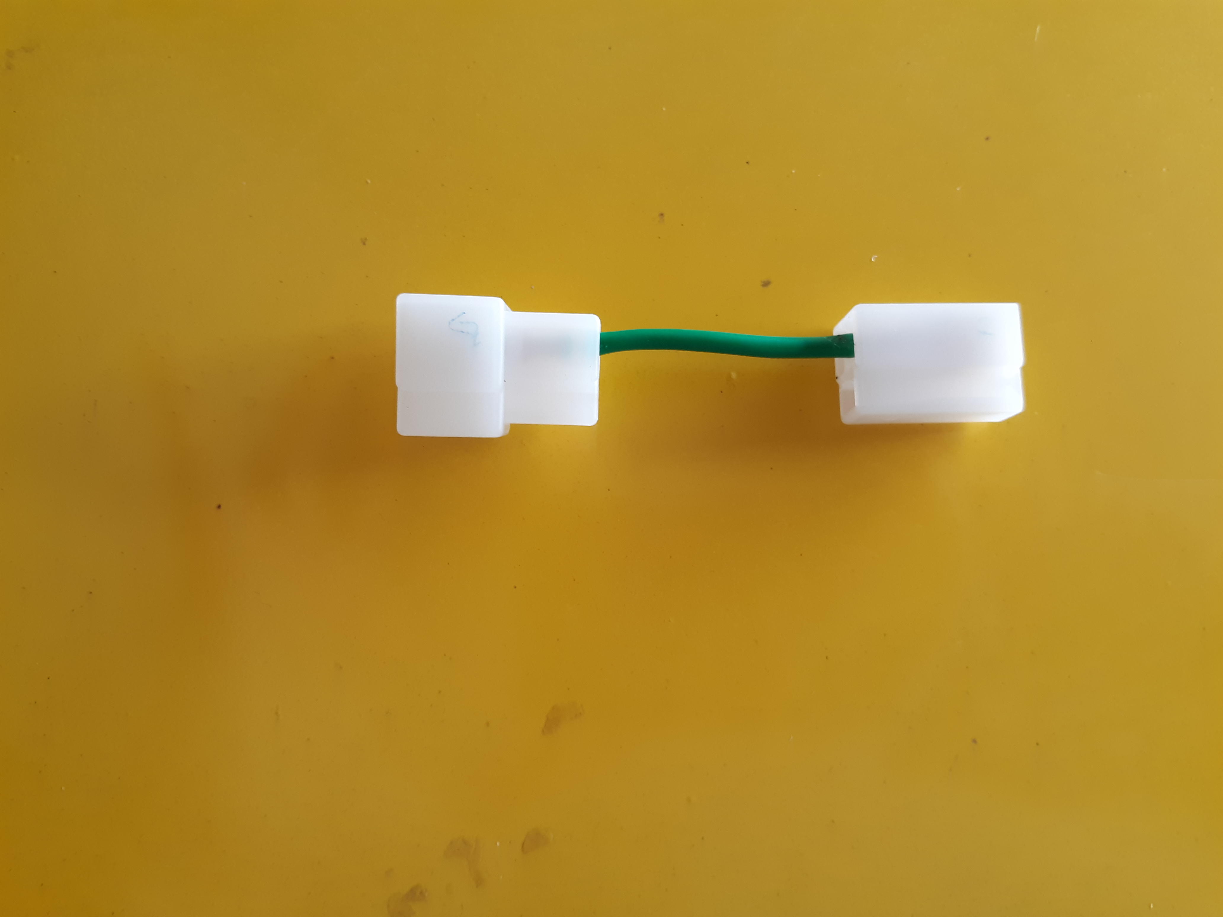
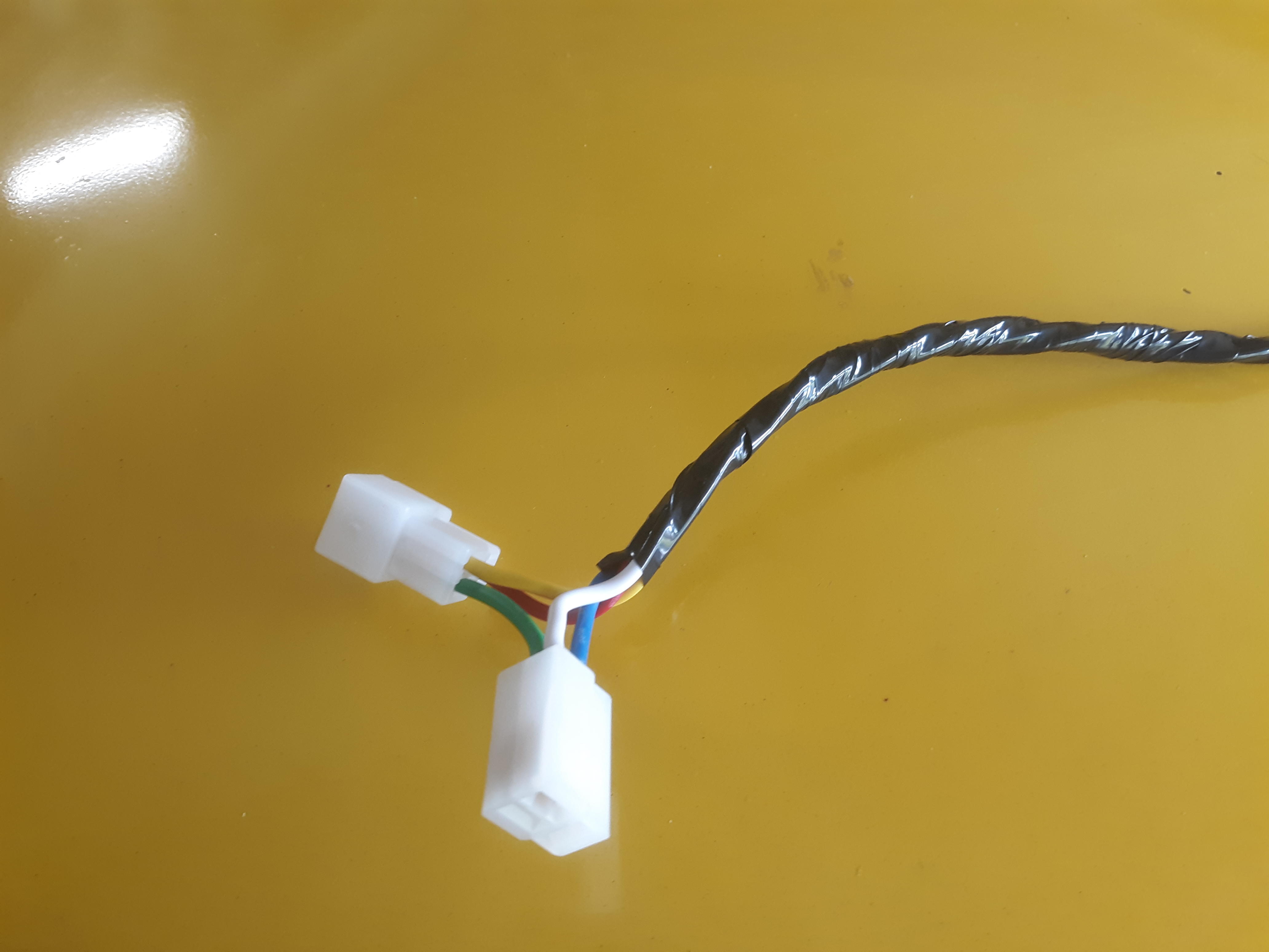
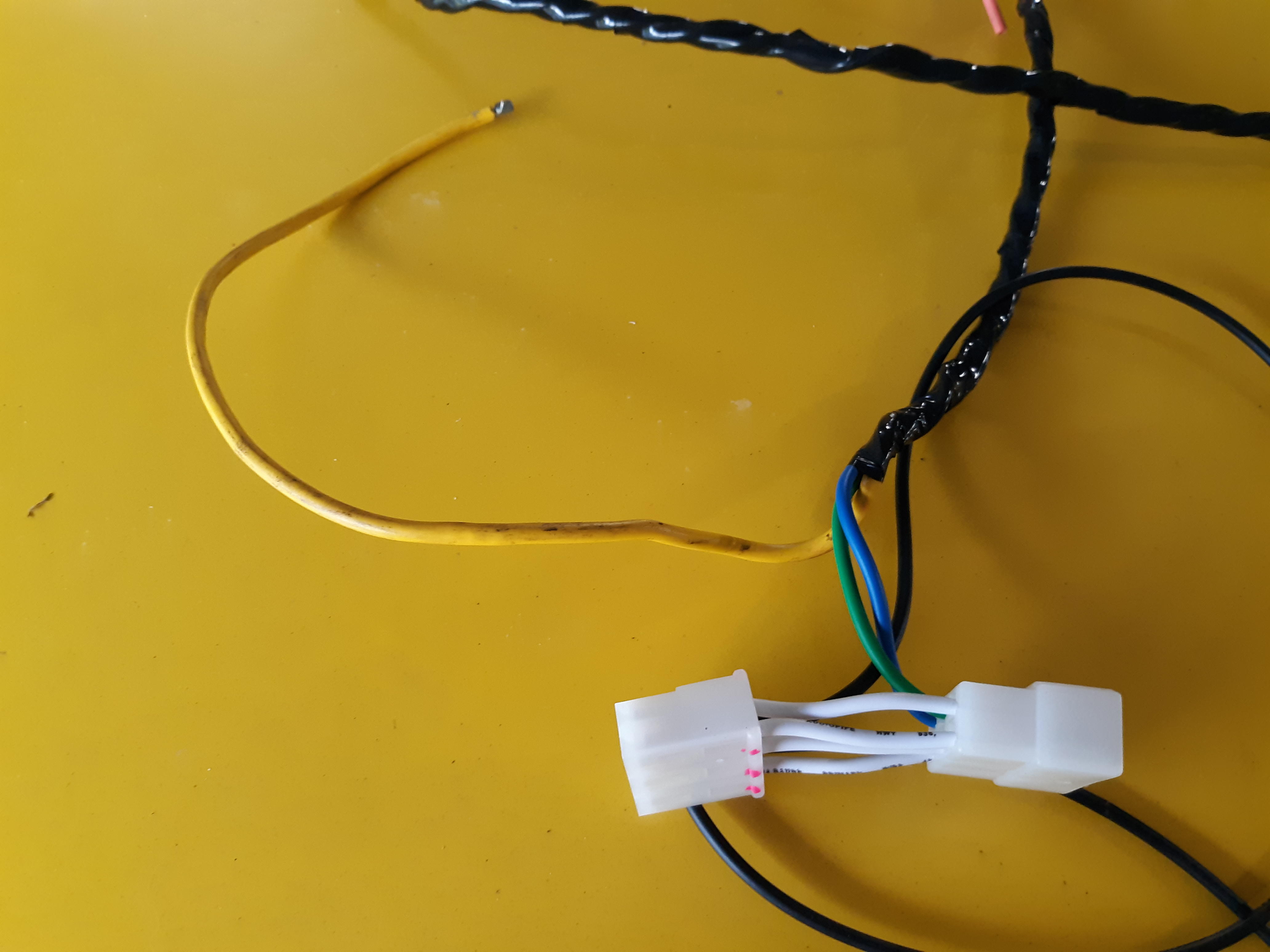
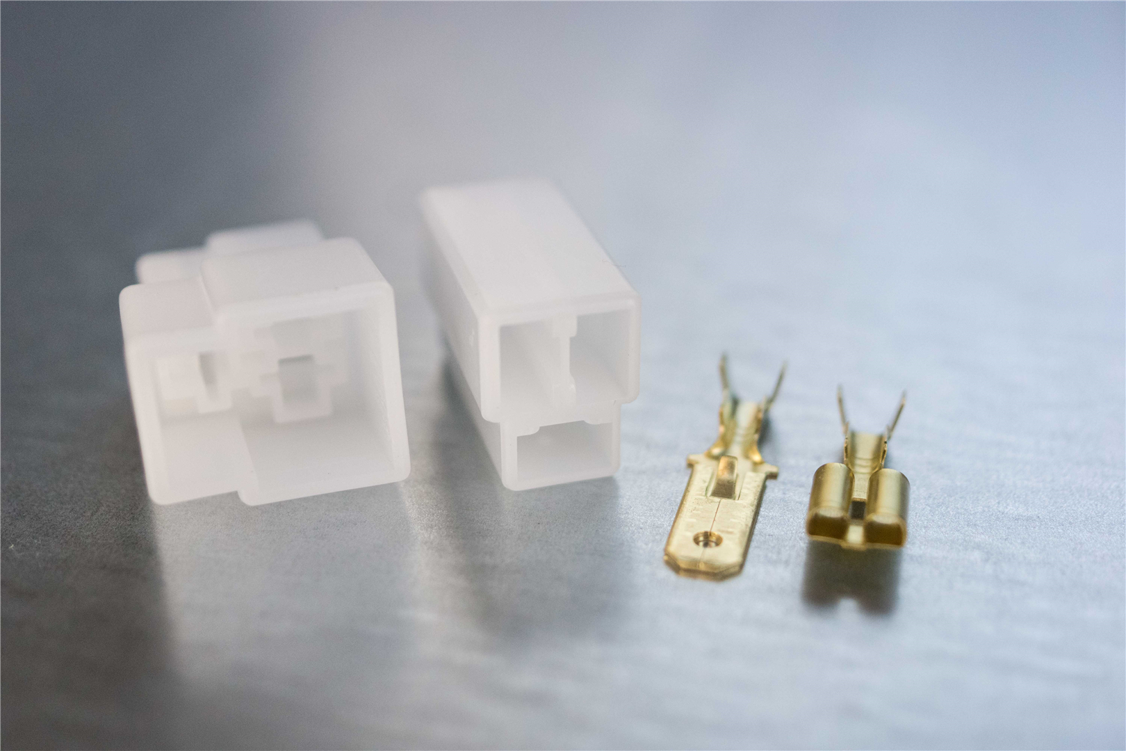
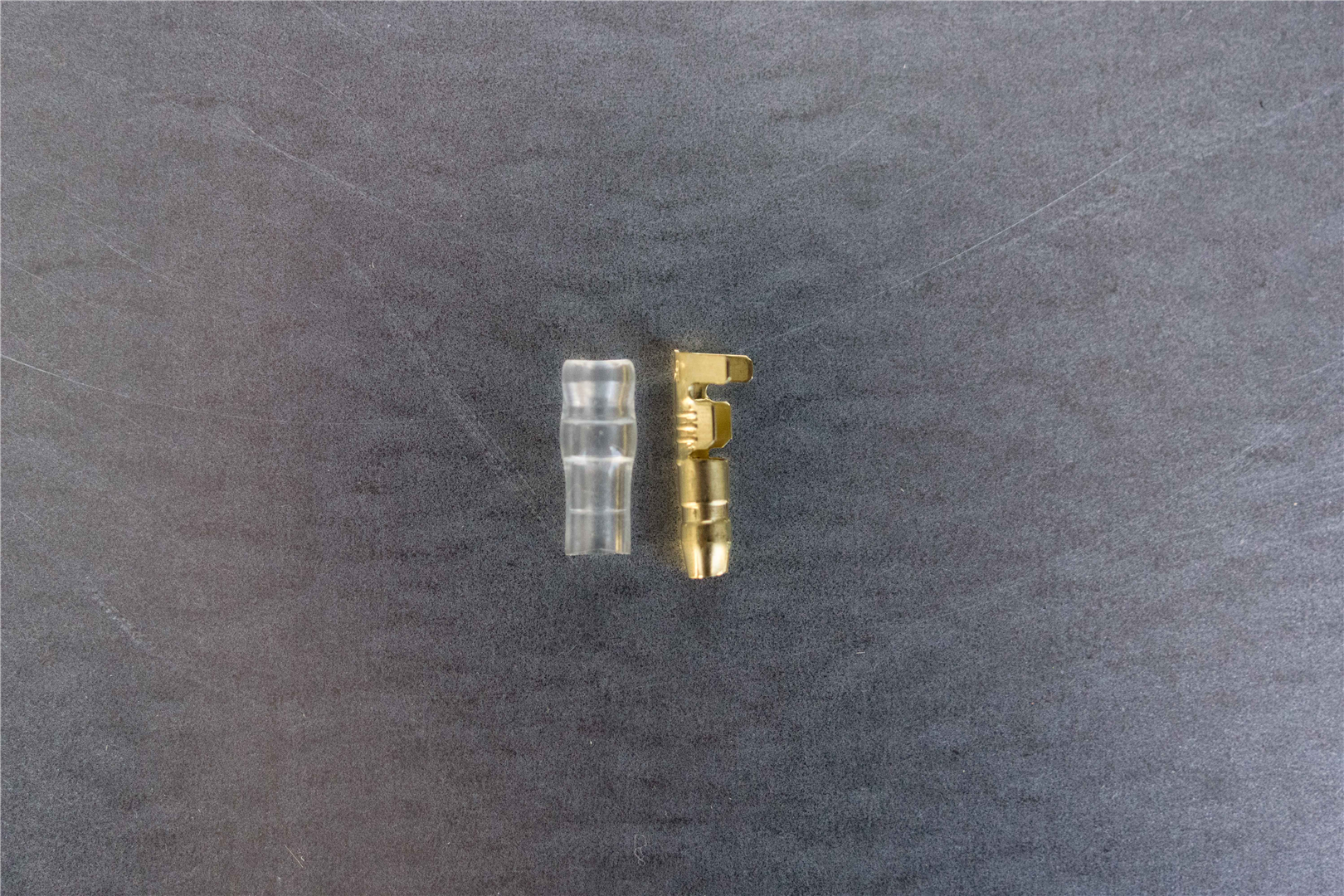
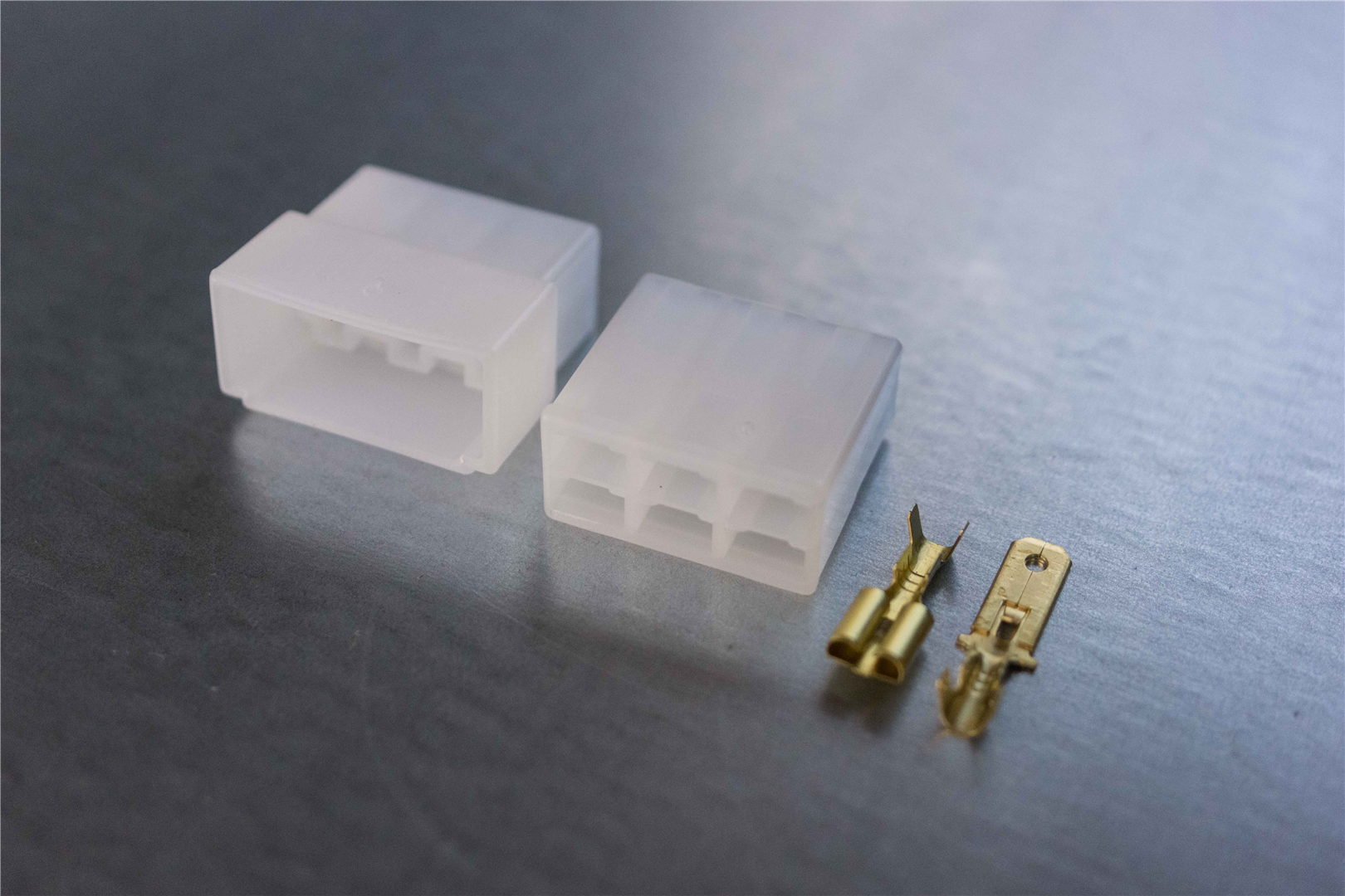
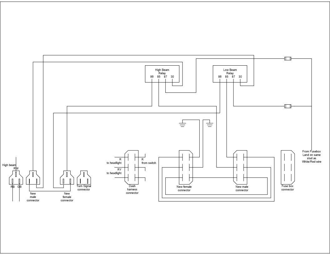
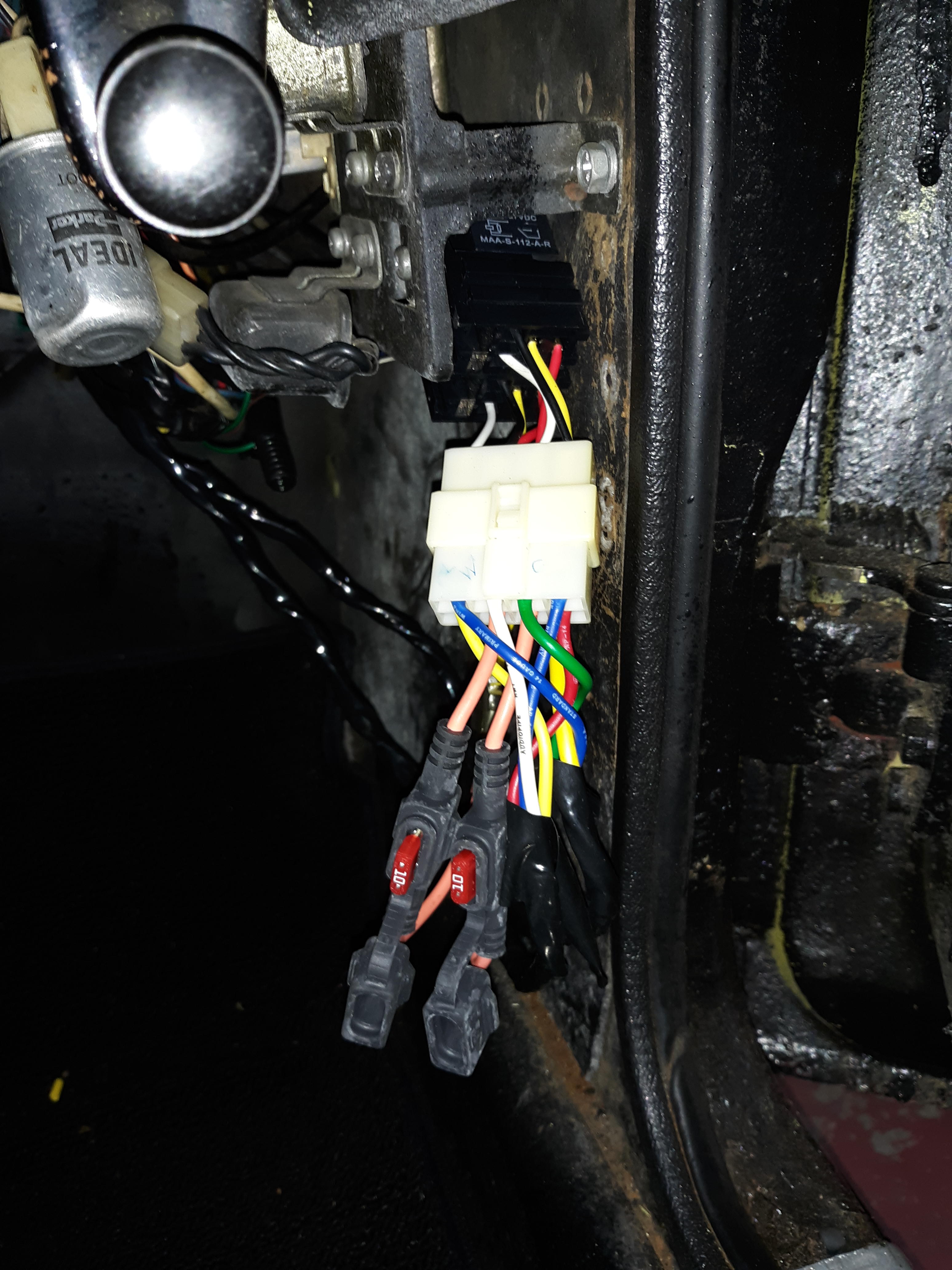
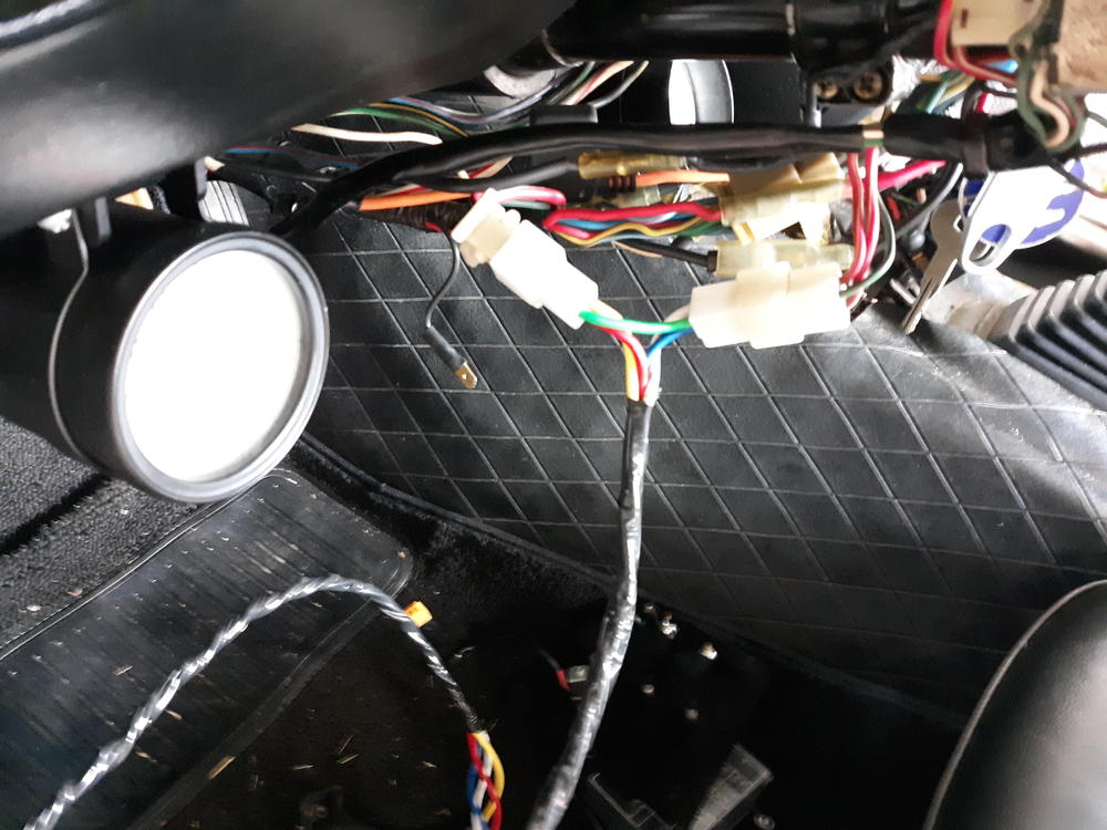
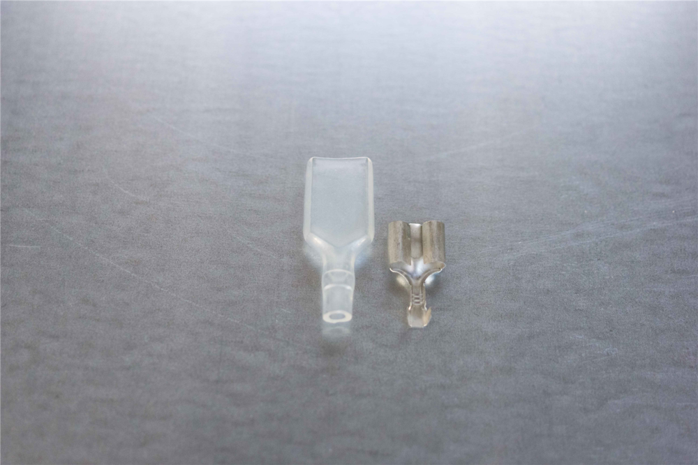
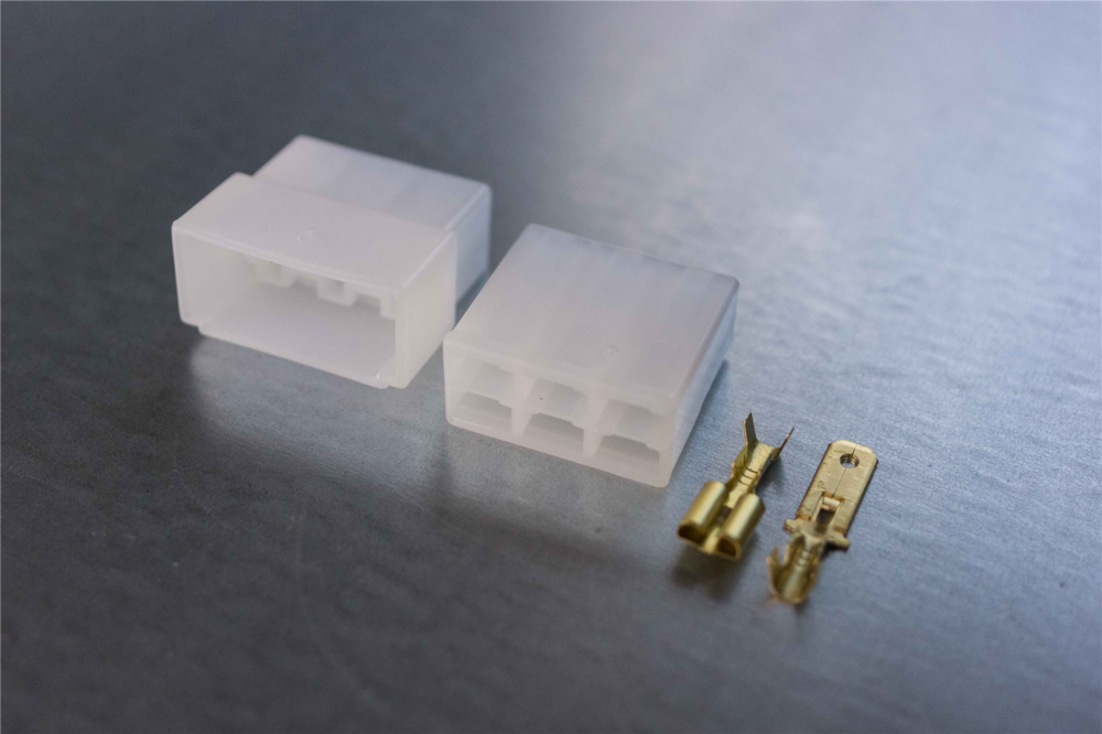
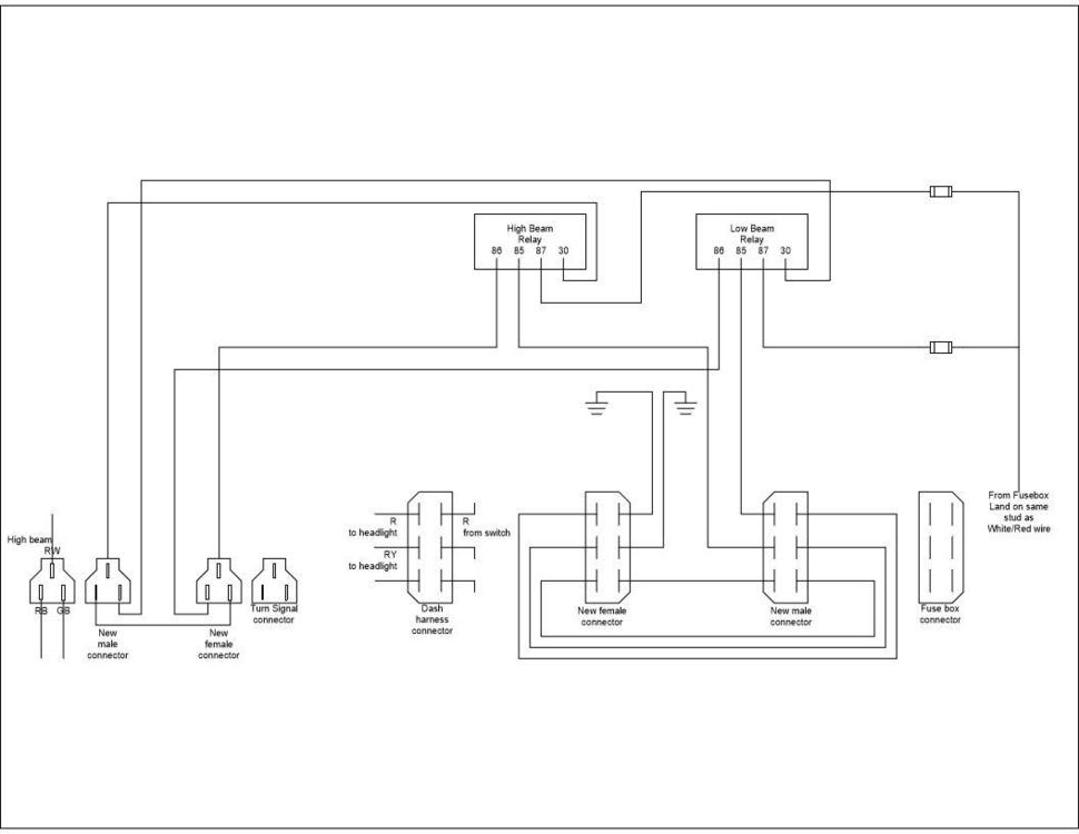
Here is a DIY headlight relay modification that I implemented on a friend's 73 this weekend. This will not work on early Z cars where the headlight switch completed the path to ground. Parts needed: 2 SPDT or SPST automotive relays with bases 14 AWG wire - It is good to have many different colors to keep things straight 12 AWG wire Electrical tape to wrap your wire bundles 1 3-pin 6.3mm non-latching connector (male and female) 1 6-pin 6.3mm non-latching connector (male and female) 2 4mm bullet terminals with insulators and 1 4mm dual socket terminal with insulator 2 inline fuse holders with 10A fuses 2 5A glass fuses 1 yellow ring terminal (solderless lug) (BTW I'm guessing on the size. I can't remember for sure) 2 blue ring terminals (solderless lug) Steps Remove the negative battery cable Remove the clamshell cover on the steering column Remove the center console and loosen the fuse box for access underneath Figure out where you can mount the relays. If you can get relay bases with mounts built in, that is preferred. Estimate the distance from the turn signal connector to the relays and from the fuse box to the relays Cut four lengths of 14 AWG wire for the run from the turn signal connector to the relays and wrap the wires together Cut a short jumper wire to run between the 3-pin male and female connectors per the drawing Note which wire you plan on landing on the connectors Crimp the pins onto the wires and insert them into the connectors Break apart the 3-pin turn signal connector and plug your new connectors into the turn signal connector in the steering column Route the new wire down the steering column and over to where the relays will be mounted. Break apart the 6-pin connector at the fuse box that has 2 red and 1 red/yellow wire. Cut 2 14 AWG wires to run from the fuse box to the relays. Cut two shorter runs of 14 AWG wire (I prefer black) for the grounds. Cut a length of 12 AWG to run from the fuse box to the relays. Cut 4 short 14 AWG jumpers to go between the male and female 6 pin connector. Wrap the 12 AWG with the 2 long 14 AWG wires. Leave enough length of 12 AWG wire to route into position Crimp pins to the wires and insert them into the appropriate connectors. Route the 12 AWG through the underside of the fuse box and attach the yellow ring terminal. Lift the rubber boot covering the terminal on the white/red wire on the underside of the fuse box. Remove the screw, and add the new ring terminal on the screw with the white/red wire. Secure the screw back onto the fuse box and cover with the rubber boot. Secure the fusebox to the car. Connect the jumper harness into the fuse box connectors. Route the ground wires over to a screw. Trim the length of the wires if necessary. Attach the blue ring terminals and secure the ground wires to the car. Route the 3 wire bundle over to the relays. Trim the length of the wires if necessary. Attach the 4mm dual socket terminal to the 12 AWG wire. Attach 1 4 mm bullet terminal to each inline fuseholder. Attach the fuseholders to the 12 AWG wire. You can do one of two things at this point. You can remove the existing wires from the relay bases and use 6.3 mm female terminals on the new wires, or you can use an 8-pin 6.33 non-latching connector to connect the relay bases to the new wires. Make the connections per the attached schematic. Change the headlight fuses in the fuse box to 5A. Attach the negative to battery. Test your headlight relays by turning on the headlight switch and alternating between high beam and low beam. Once you verify relay operation, install 10A fuses in the inline fuseholders. Replace the center console and clamshell. Here is the schematic: This reverses the original design to have 2 positive wires going to the headlights and 1 negative. This allows the use of LED headlights.


-
You aren't the first to use an LED where the incandescent bulb is needed. I doubt you'll be the last. I'm glad @Dave WM thought to mention that. Here is another old-school application where incandescent lights are needed. In the past to synchronize an AC generator to a live system, you had two lights that are connected in series and to the same bus phase on each side of the breaker. When the sources were 180 degrees out of phase, the bulbs burned bright. The closer the generator was to being in phase with the bus, the dimmer the lights would get. When the lights were extremely dim or out, it was safe to close the breaker...if you were quick enough. Some people still want this antiquated functionality on new equipment, but they also want LED light bulbs. I submitted a design package to a consultant complete with my parts list that had LED bulbs and the incandescent bulbs for the synchronization panel. The consultant wrote back that his specification called for LED lights. I replied that the incandescent lights were for the synchronization panel that he also specified. That was the end of that conversation. Yes, the life of an electrical engineer can be so exciting...just like arguing on the internet.
-
No, that's not what I said. A short would be a bad thing. You ruled that out. That's why I gave you another test to run. Pull the sending unit and see if there is gas on the thermistor can.
-
Well, it looks like you don't have a short to ground between the fuel light and the sending unit, otherwise you would have gotten the fuel light with the sending unit unplugged. You seem to have good resistance at the thermistor (1kOhm between the yellow/blue and black wires). You could pull the sending unit and see if the thermistor was covered with gas. It seems like it is not immersed in fuel with the meter readings you got.
-
Oh and you might turn the key to ON with the sending unit disconnected. If you get the low fuel light in that case, you have a cross connection.
-
So now measure resistance from the yellow/blue to the black on the wiring harness side of the connector. After we rule out a short In the wiring harness, you'll take some voltage readings.
-
-
Disconnect the fuel sending unit. Check resistance on both sides of the connector from yellow/blue to black. (Note: the wire color could be different on the sending unit. Check the pin that goes to the yellow/blue wire in the body harness.) Report your results here.
-
-
No buzzer for the passenger door. The wiring is different between the two switches. There is an extra wire on the driver side door switch for the key-in buzzer.
-
The switch body/wiring is the same 70-73.
-
I think I'll be doing that soon for Bill's car, @David Downs. I have the carbs tuned nice, but it is starving for fuel.
-
I think @Dave WM was using two bulbs because they were 6 volt bulbs.
-
There are different part numbers for the hazard flasher and turn signal flasher in the parts manual. The hazard flasher part number is still available in the Nissan system, but the turn signal part numbers are NLA. Of course, when I swapped out all of the lights to LED, I went with electronic flashers that for all intents and purposes are interchangeable...but I digress.
-
That's the problem when you license and replicate someone else's design. You usually copy the design flaws, too. You won't find connectors/narrow pins like the 75-77 EFI relay connectors anywhere else in the Z. Those came the Bosch design. Of course, if my designs were perfect, I wouldn't need another engineer to review them...and there would never be red-lines on the drawings from the production floor/startup. Heck, I just carry a red pen with me at work to save time. I never have to hunt for one.