.JPG.cfcada9cf1c1b502df3f5f2f2ca3ff36.JPG)

SteveJ
Community Member
-
Joined
-
Last visited
Everything posted by SteveJ
-
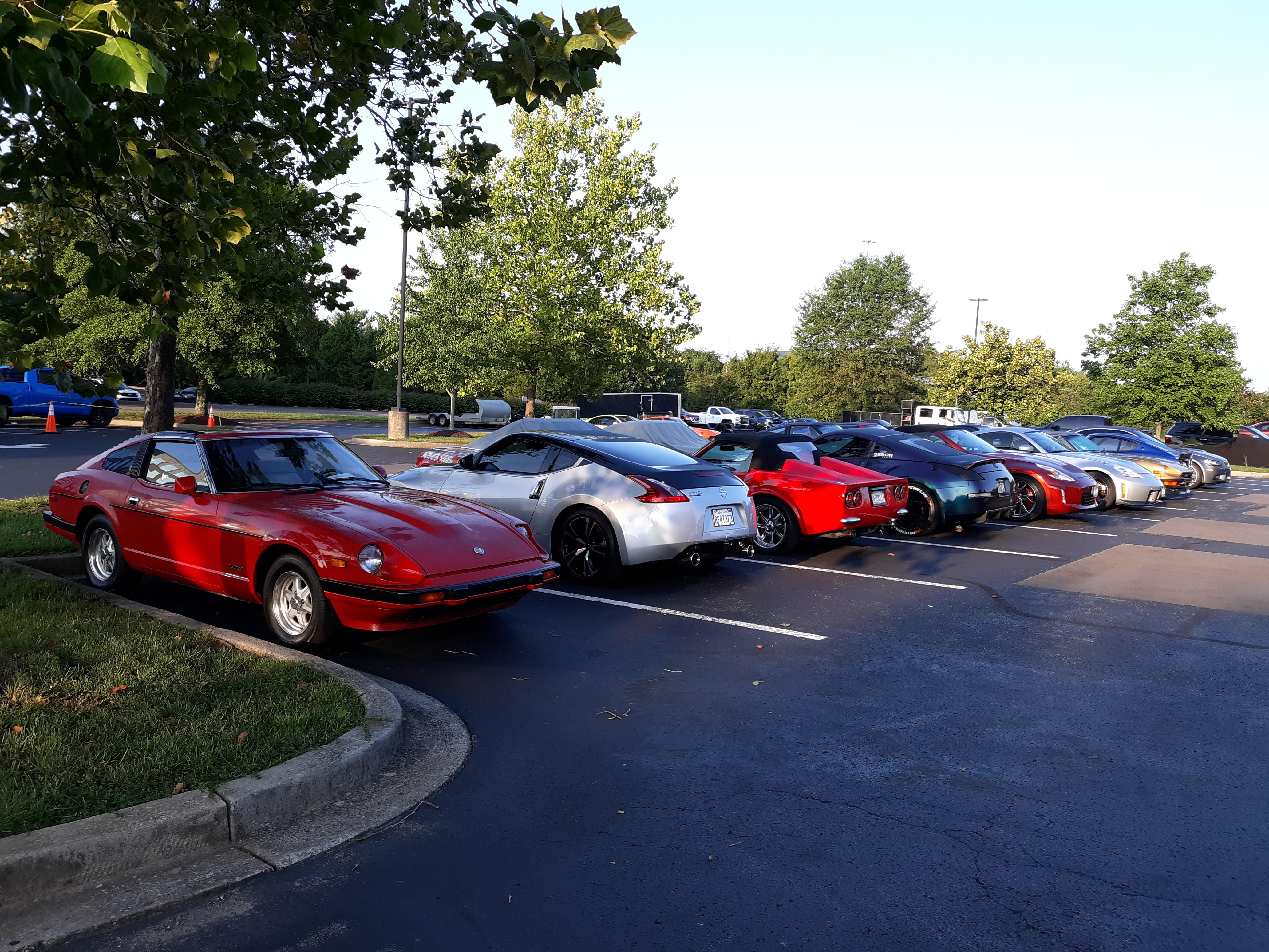
@240260280, here are a couple of more photos: https://photos.app.goo.gl/TSri4pb513RnJ1KNA https://photos.app.goo.gl/5Q73Rqkmo8Tp1Gj7A And there are some photos in this album, too: https://photos.app.goo.gl/xLN3ymszPDNSx87j6
-
That's right. It's got the 2.0L engine, too.
-
There are some in this album: https://photos.app.goo.gl/UxdKfupPw7E6ZDyh6 And here is one from the People's Choice show: https://photos.app.goo.gl/bE7jfujnnHmo35xo9
-
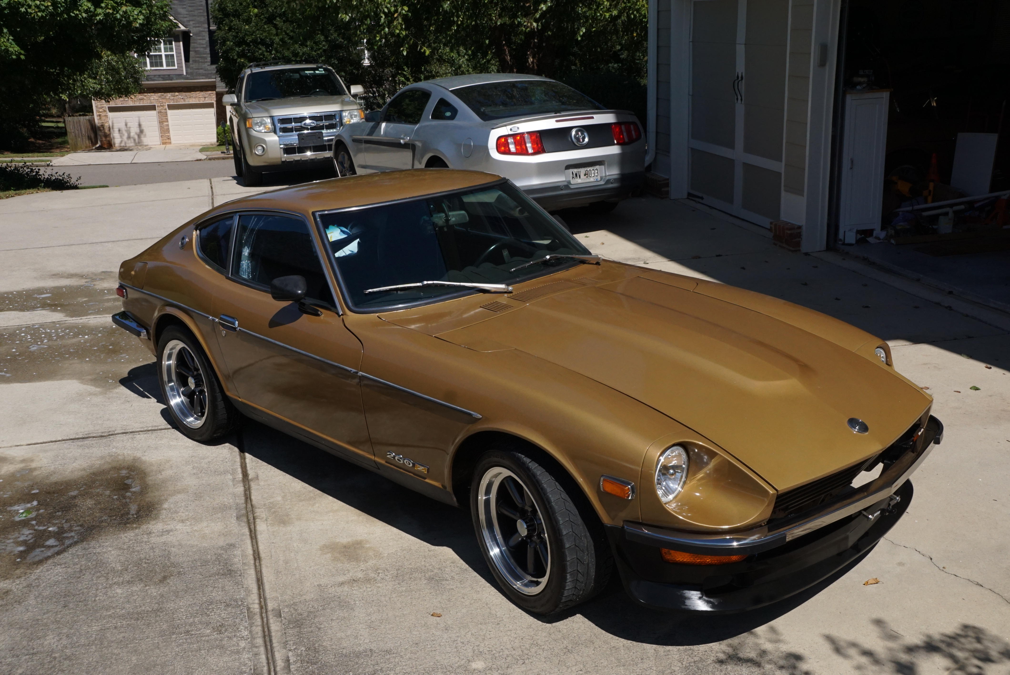
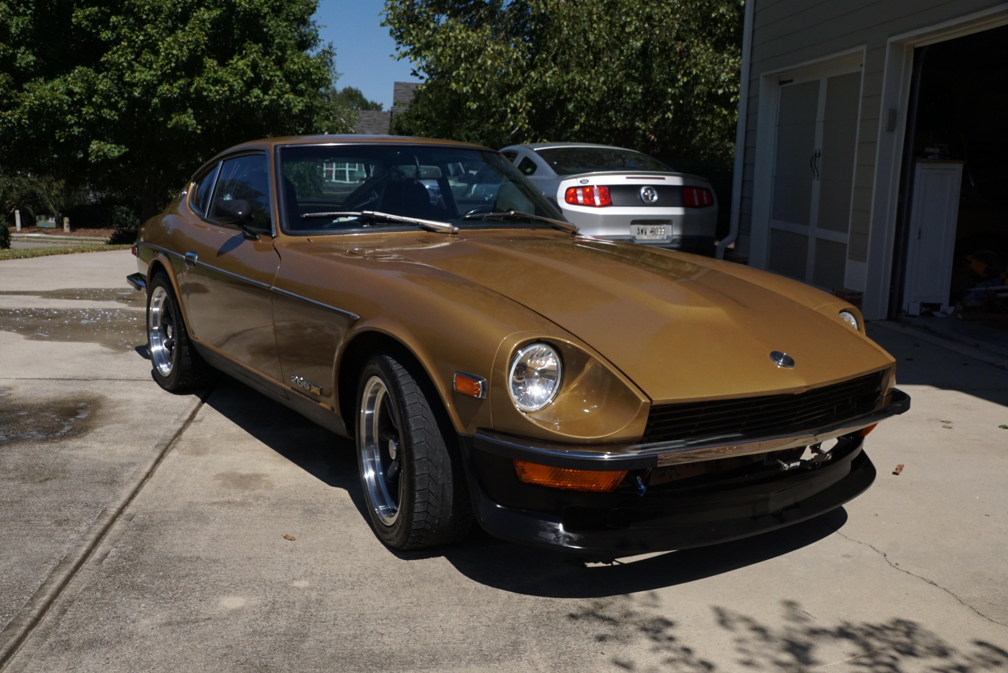
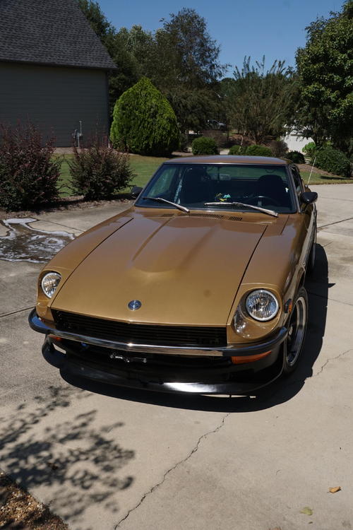
I took today off from work to recover from the ZCON trip, so I gave the 260Z a bath and used some C2 ceramic on it.


-
-
While attendance was down due to Covid, a lot of the hard core people were in attendance. For you people out west and in the plains, ZCON 2021 will be August 16-21 in Colorado Springs.
-
I got my video of the People's Choice Car Show uploaded. If you can, watch it in 4K.
-
He arrived on Monday and left on Wednesday. I had a chance to chat with him at the reveal of the Z Proto on Tuesday.
-
Interesting. I'll have to keep this one in mind.
-
 It depends upon the tire width. I have 16x7 with 195mm wide tires and no rub on my 260Z.
 -
-
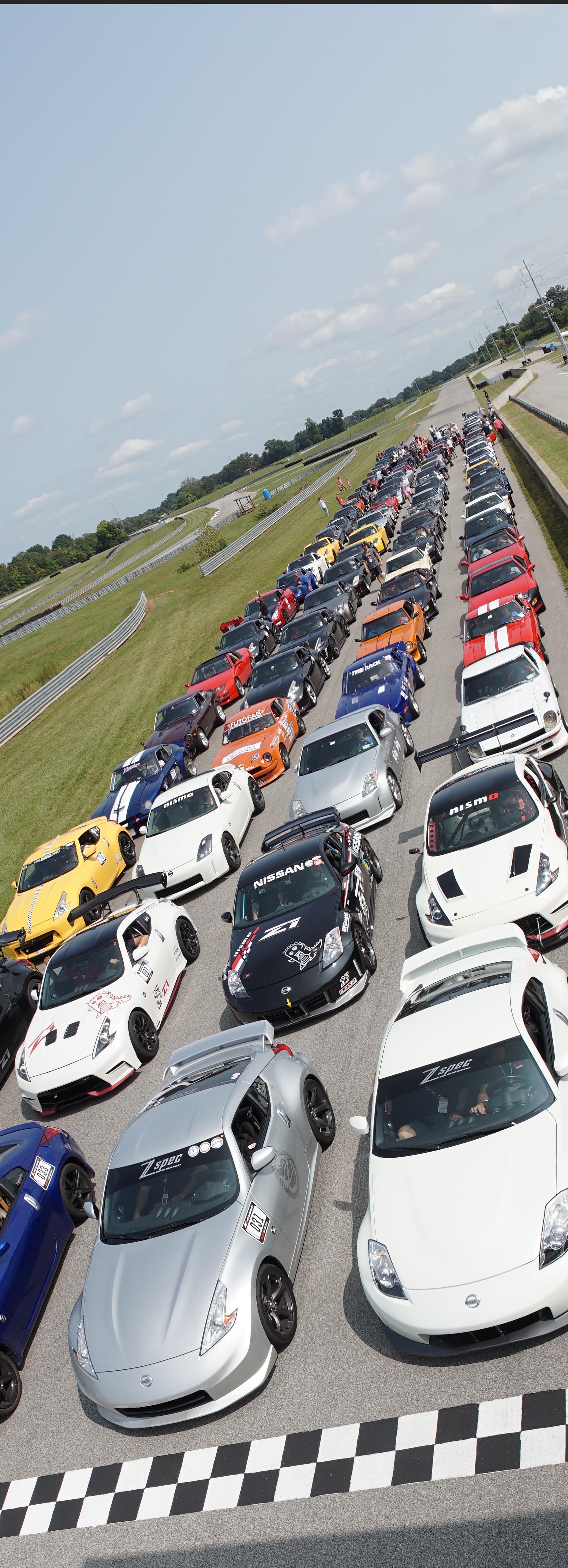
Here is a panoramic photo I shot of the cars lined up on the front stretch. Unfortunately some of the cars up front got cut off. Before that, I was in the garage area talking on the phone with a friend. Then Chris Karl, head of the ZCCA, asked me if I wanted to ride along with him on the parade laps. I told my friend that I had to go, grabbed my camera bag, and hopped into the passenger seat. (Well, as much as my old bones would let me hop into the passenger seat of a 370Z.) I didn't have a chance to get one of my action cameras with gimbal, so I got my old handycam out of my computer bag and did my best to hold it steady while Chris was putting on a show for the ZCON videographers. Before that, the cars were lining up double file to go onto the track for parade laps. Again, no time for the steady camera equipment (sorry!), but I thought the video looked neat.

-
Dang it. Someone wiped out at track day. I thought it was Greg IRA from a distance. The driver is okay.
-
-
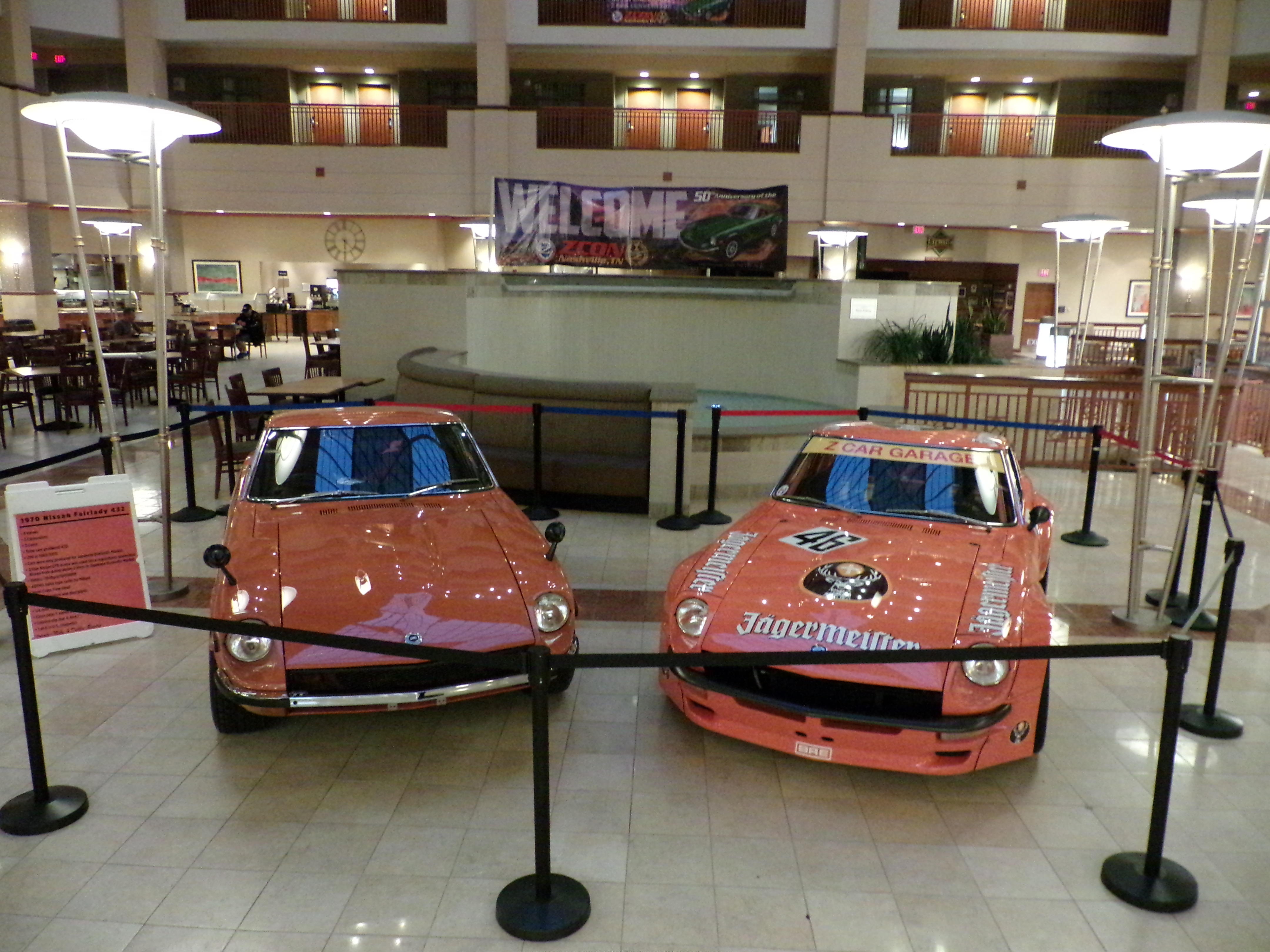
Nissan put on a great show for the ZCON attendees today. The setting was great. They fed us and had cars from the Heritage collection on display. I had a blast. https://photos.app.goo.gl/NYnCcyg1rKe3VF6K8
-
Here's the video to go with the photos from the Judged Car Show.
-
Oh, and if they were broadcasting when someone in Nashville yelled, "Save the manuals!", that was me.
-
Alphonso said something during the presentation that I have been saying for a while. The original Z was successful because it was more than just another sporty car. It has a practical side (that I put to good use stuffing mine with all sorts of tools, clothes, camera equipment, etc. for the trip to ZCON) that made it where it could be your only car (if you didn't have kids). I'm hoping there is plenty of that in the new Z.
-
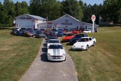
Judged Car Show photos. The video is being created as I type. https://photos.app.goo.gl/a3SkgrHAVDRmx82C8
-
Here are the rest of Monday's photos and a video from Suds & Shine: https://photos.app.goo.gl/UaeiMfMAhHnzXiQu6
-
What's worse: you saying that, or me immediately knowing where that came from?
-
Are you ready for the photo flood to start? Day 1 (or is it Day 0?) https://photos.app.goo.gl/xLN3ymszPDNSx87j6 This morning https://photos.app.goo.gl/UxdKfupPw7E6ZDyh6

-
Actually, you need to post a photos of the passenger side headlight out of the car (front/side/back). If it has two adjustment screws, then it's possibly one of two things: 1. Someone replaced the headlight in the past with a driver side headlight. 2. You somehow managed to mount the headlight 90 degrees out. Without being able to look closely and not knowing much about your car, I would consider #1 first. Getting back to an earlier topic in the thread, I think I found a better source for the DRLs. The washer fluid motor isn't close to the front, but you could use power from the blue/red wire, again with an inline fuse right after where you tap. That way if the fuse blows, you only lose the DRLs and you still have your wipers.
-
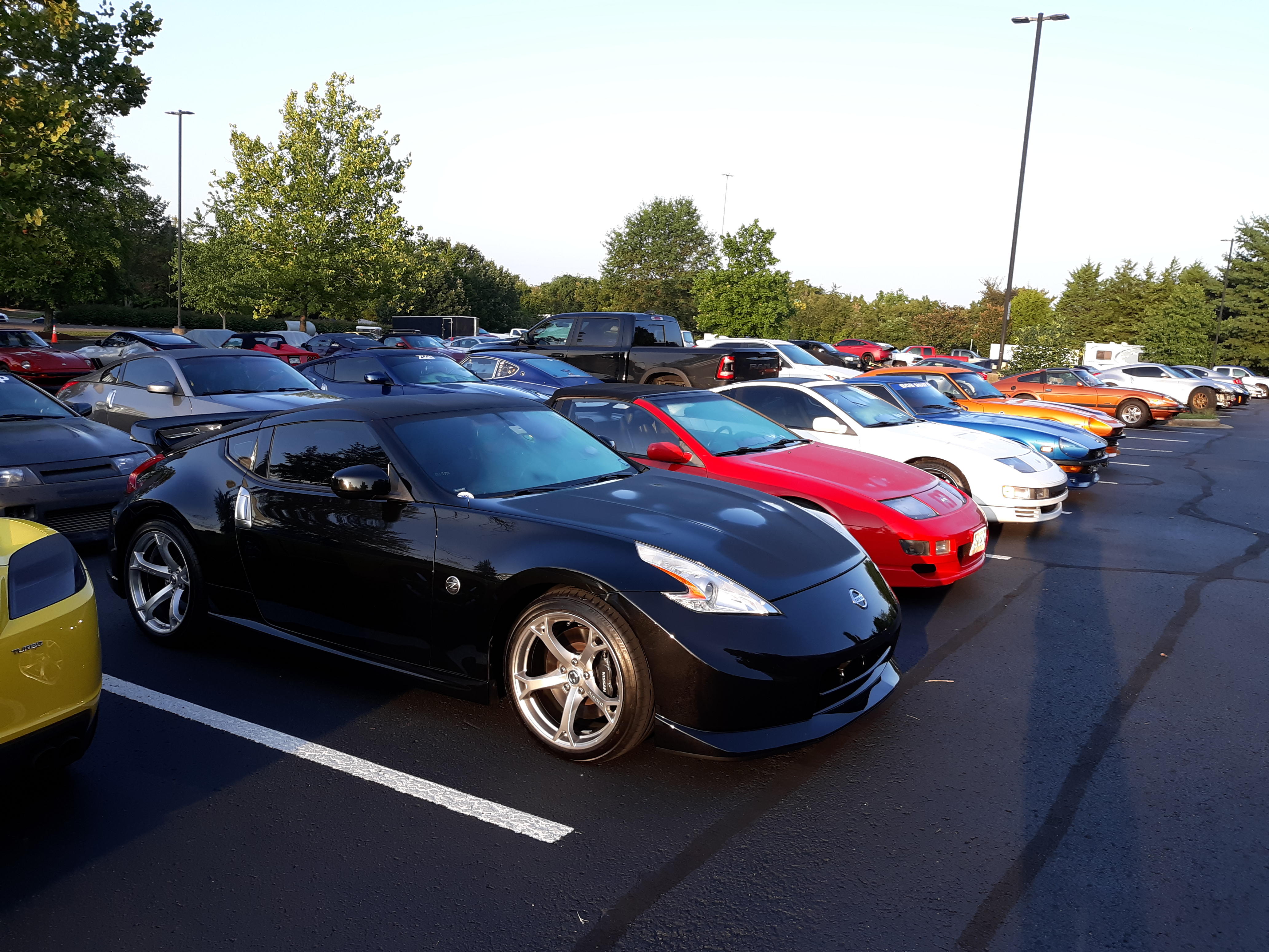
Some people got preferred paking in the hotel.
-
With using the coil, you must use an inline fuse, or a short will stop your car dead. I will try to find another source, but it won't be until much later today. I'm hitting the road for ZCON. As for the headlight adjustment not lining up, that should be part of the factory assembly. Please post clear photos.
-
Yes, I'm bad about discovering something wrong with the electrical diagrams and not telling everybody.