HusseinHolland
Community Member
-
Joined
-
Last visited
Everything posted by HusseinHolland
-
I didn't realize I was missing this until I was scanning through the FSM looking for the PCV. On old SOHC Volvos they use a "Flame Trap", between the air inlet and valve cover with a small vacuum draw that serves the same purpose, but that's it, they don't have a PCV in addition. Don't think I can make one of those work, so I guess I'm looking for the 20ga shotgun cleaning brush to mod 😄
-
Thank you. The top mount bracket? It has a raised ridge & folded rear edge, I think it will be OK. I know what you mean though. I tried to locate a spare bracket with similar form without success. I can always remake it DTR if need be. Yeah, I wanted to drop the height & move the booster vacuum rearward. Vacuum draw out the end of the plenum will be much the same as the top rear. I'll be revising the AC lines coming out the firewall & wanted as much space in that area as possible until I have that all figured out.
-
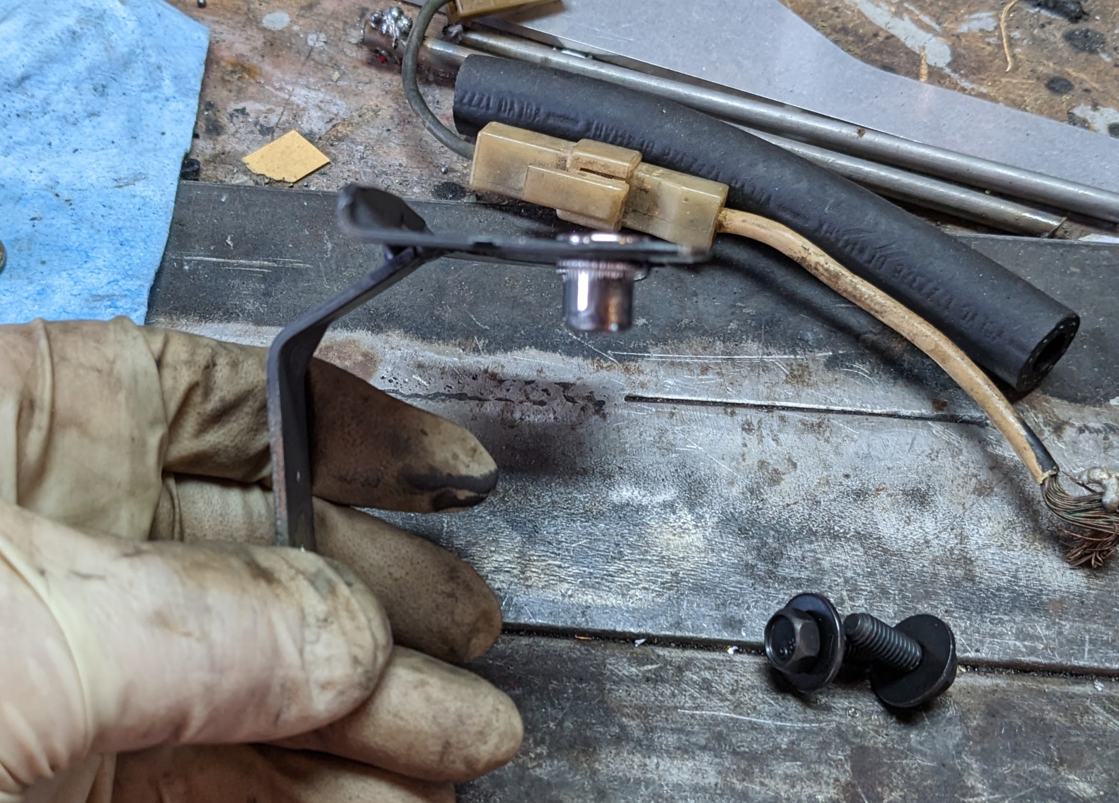
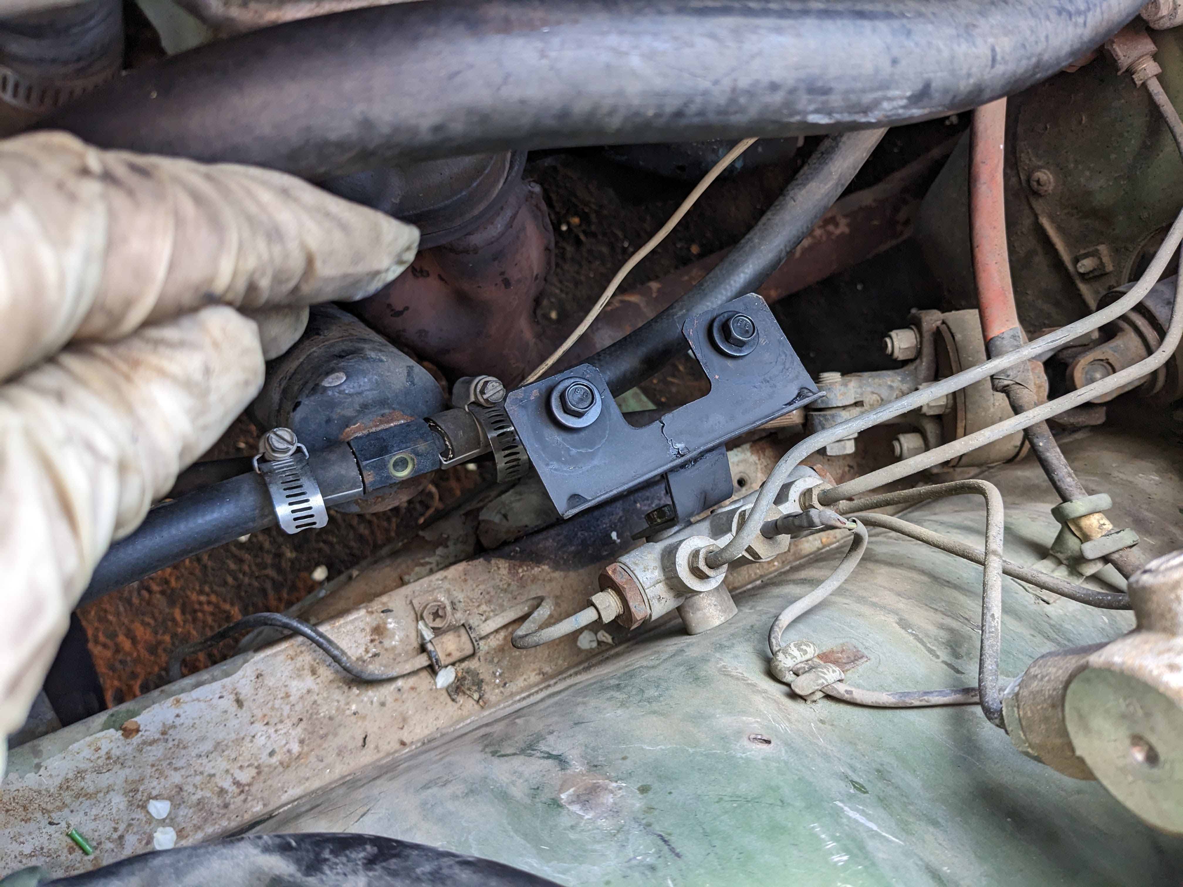
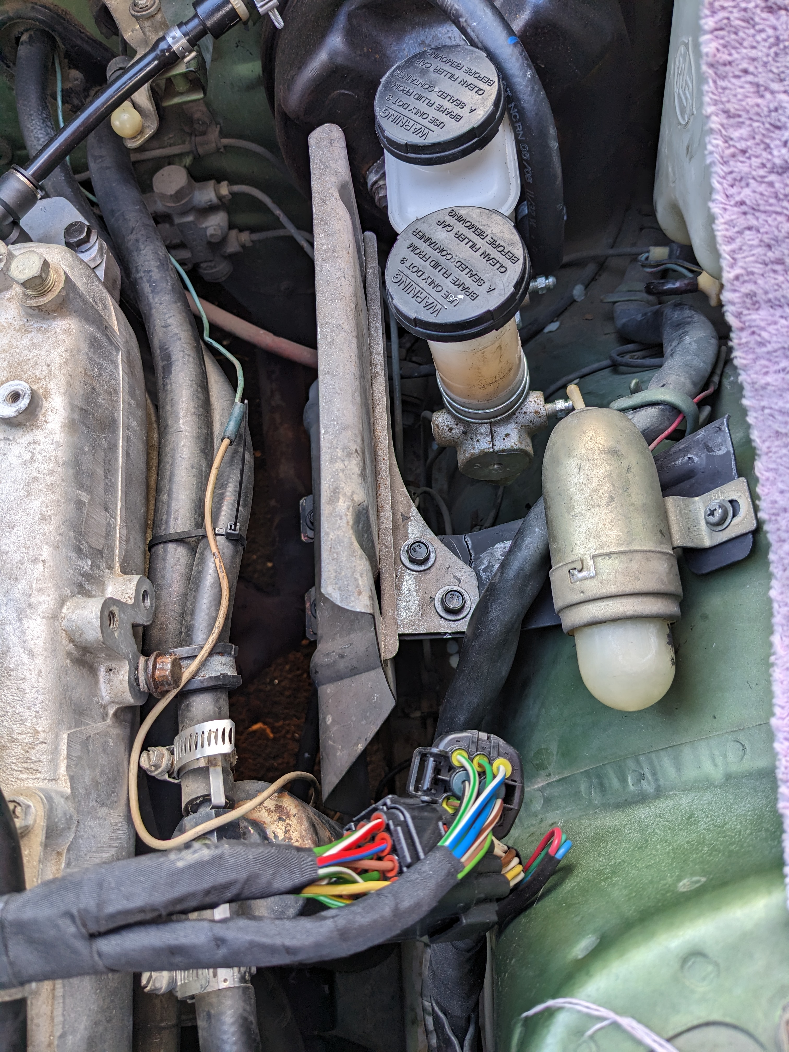
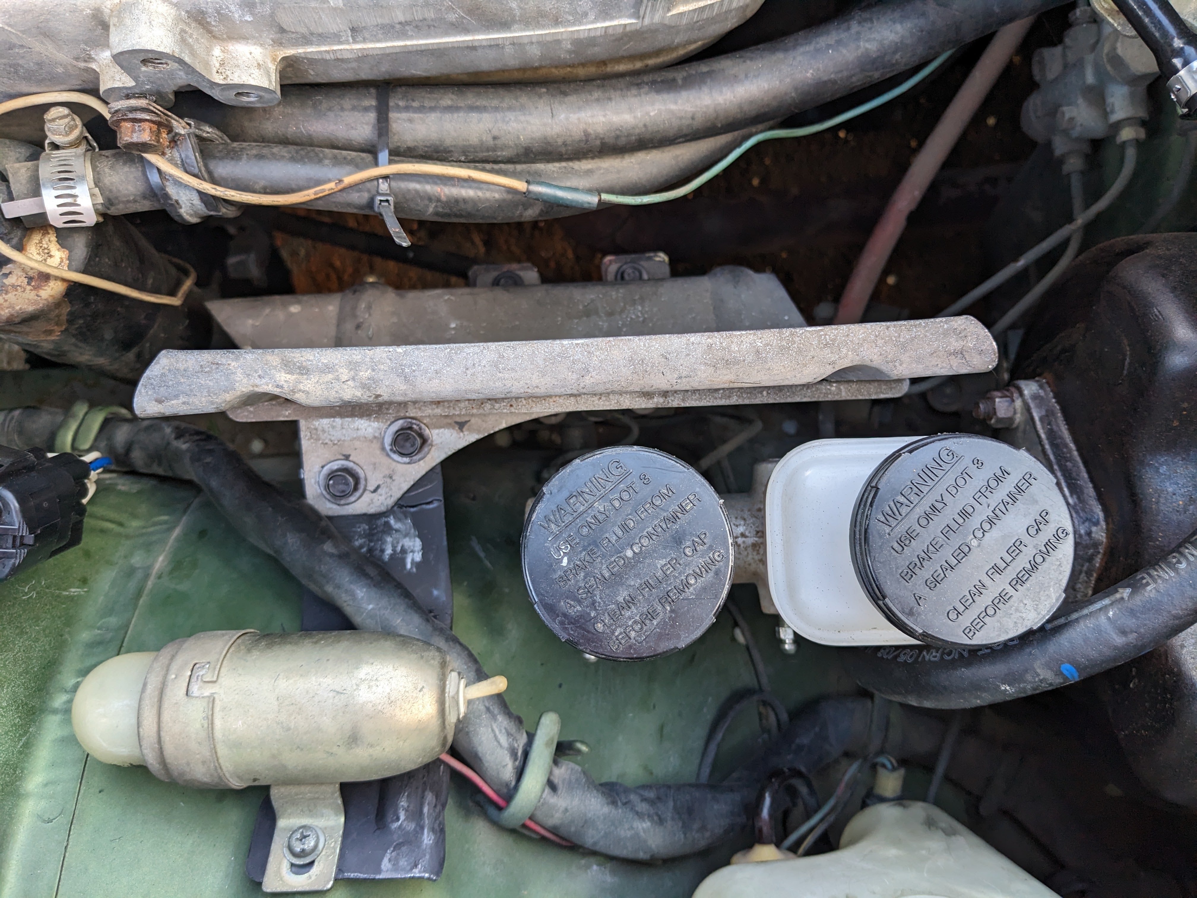
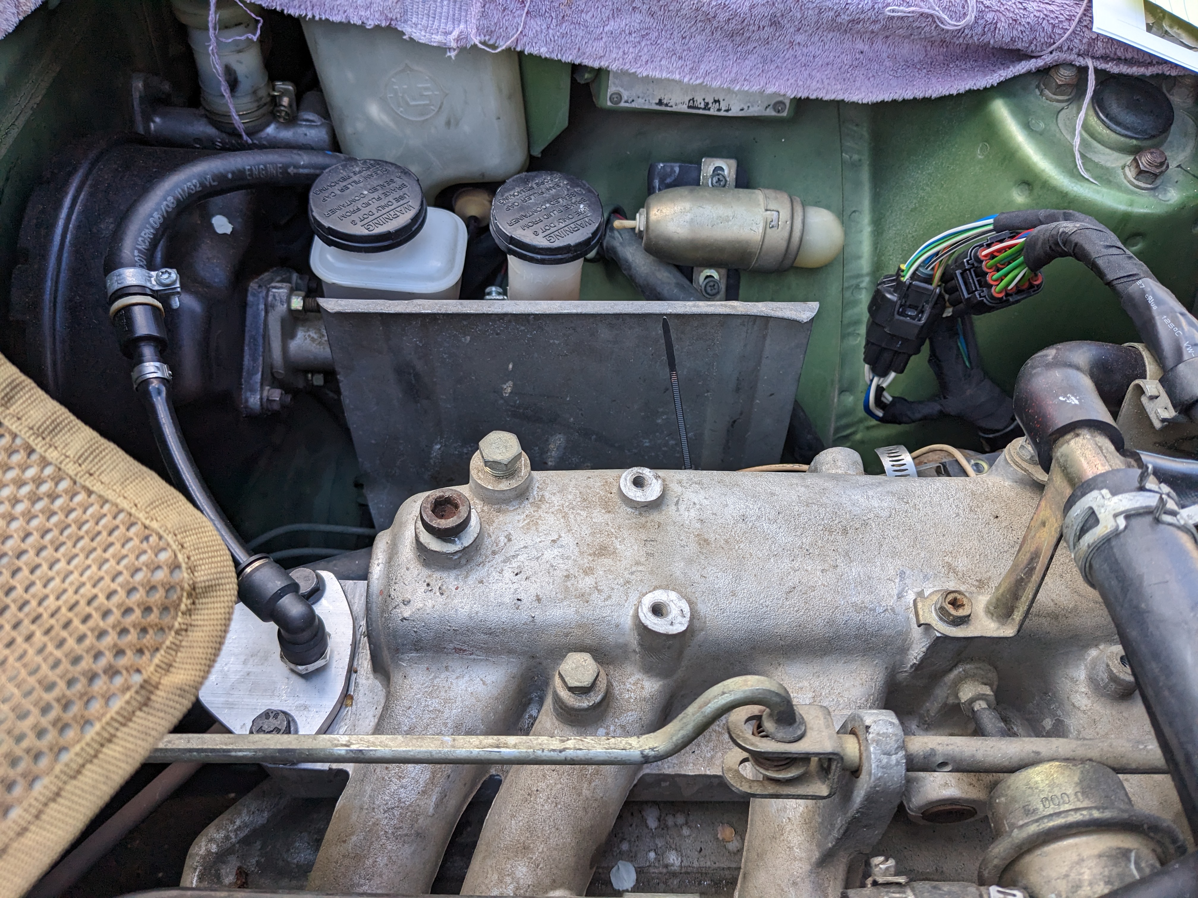
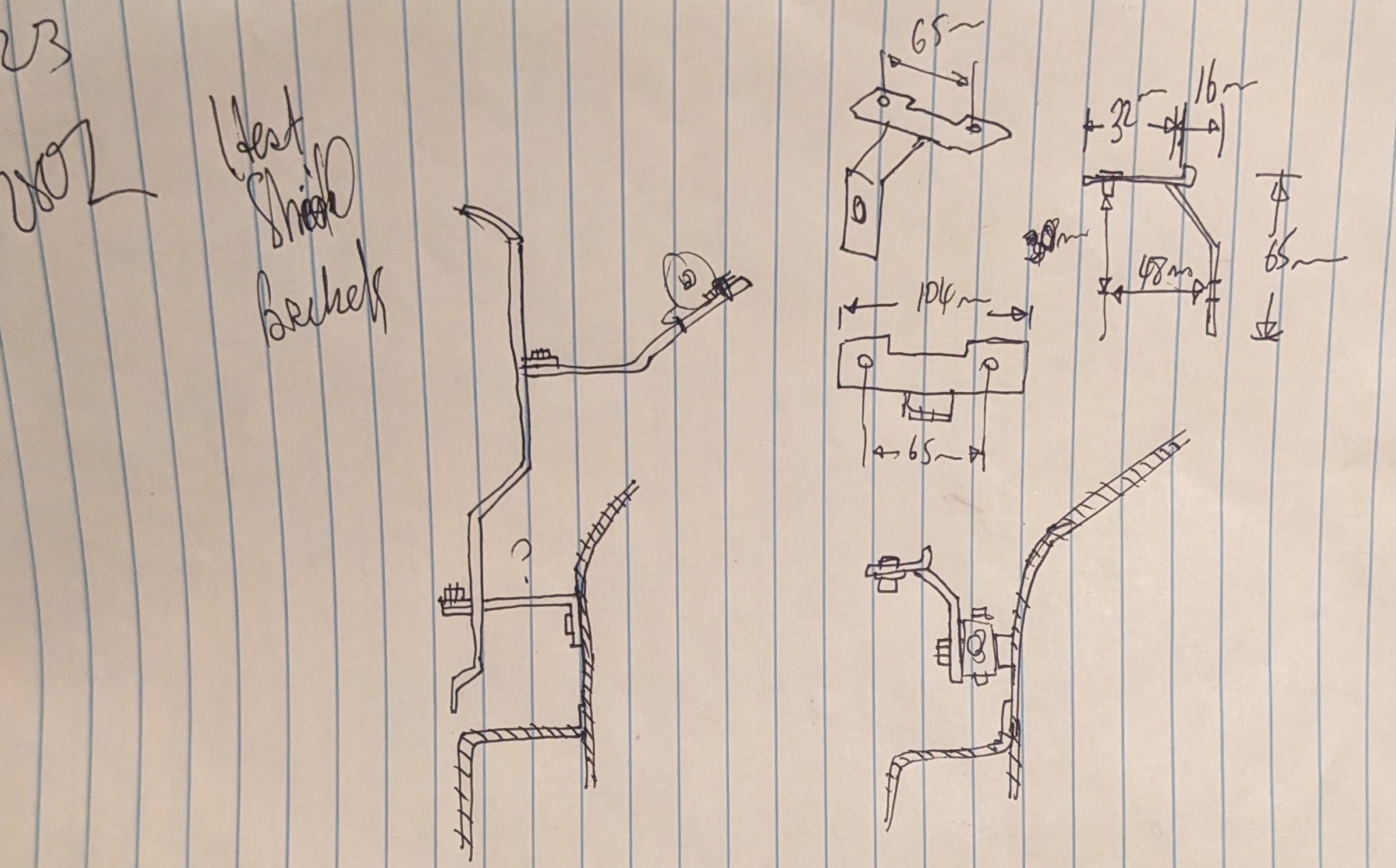
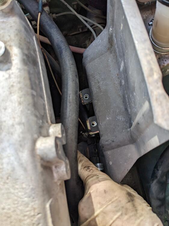
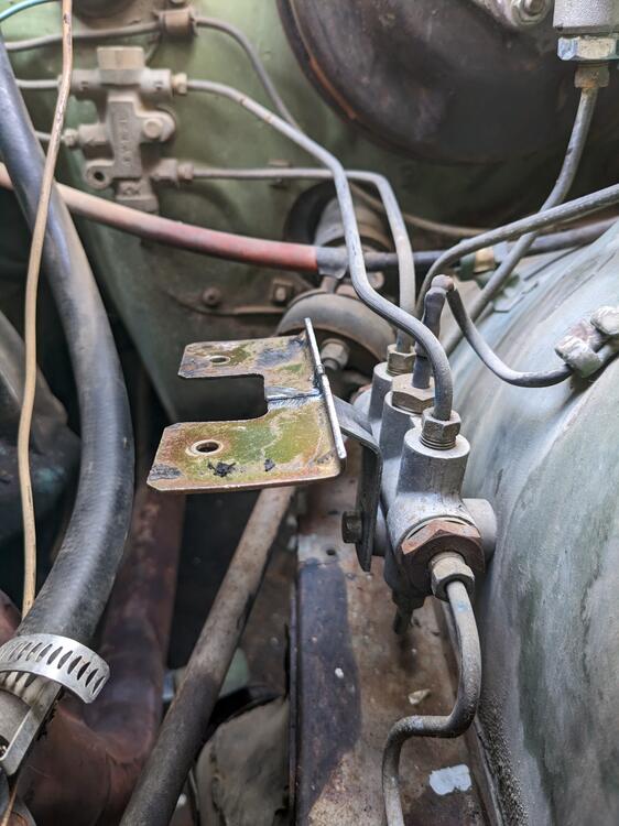
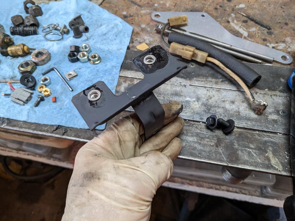
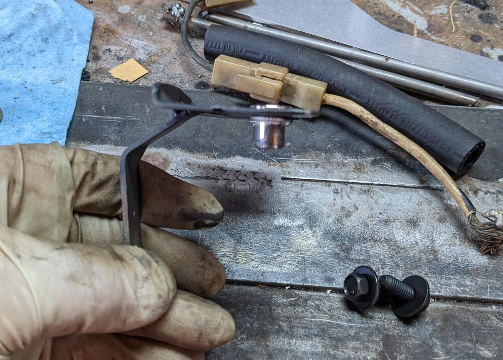
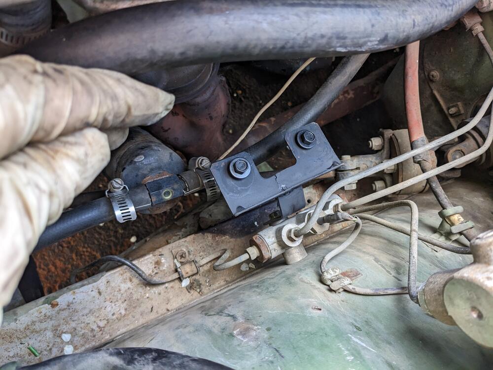
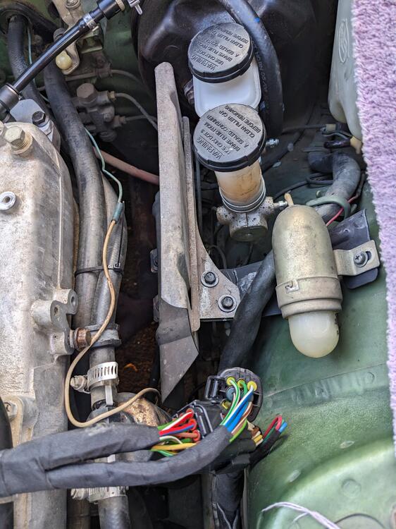
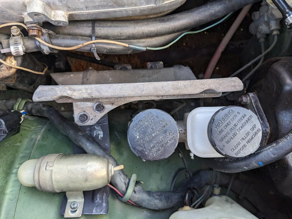
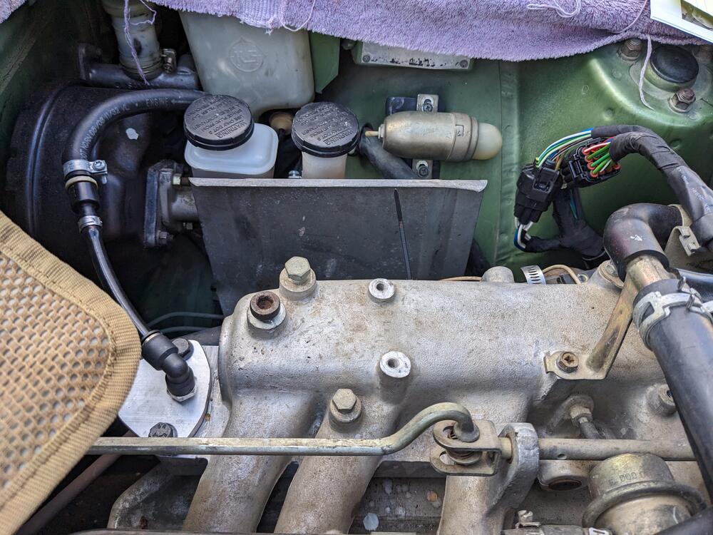
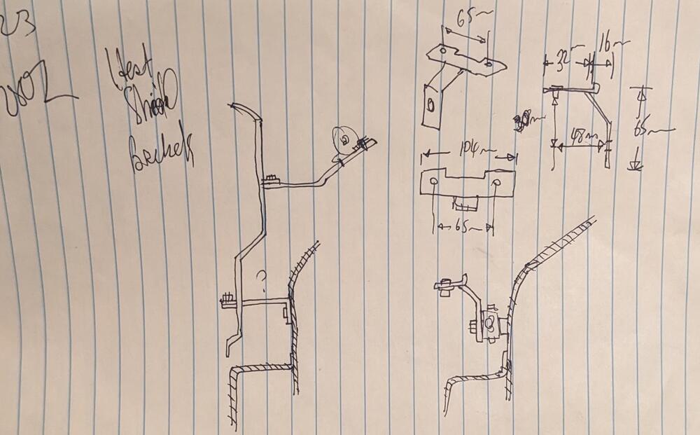
I made a bracket when I got home - I saw that the brake valve was in the location that made sense to mount to - confirmed by Gwri8's pics. I wish I had checked back here first & seen his & your pics above, that would have simplified things a little 😬 In any event, this is what I made tack welded a few pieces of cut up bracketry to test I only have a finger width between the back lower edge & the steering shaft, so I didn't want to move it any further rearward . Made the upper support bracket to have 2 mounts at the shield, and holes to allow the stock bay light bracket to stay where it belongs. Engine harness lays nicely over the bracket. I curved the left side to both make it more rigid, and to make sure there is no harsh edge for the harness to chafe on.
-
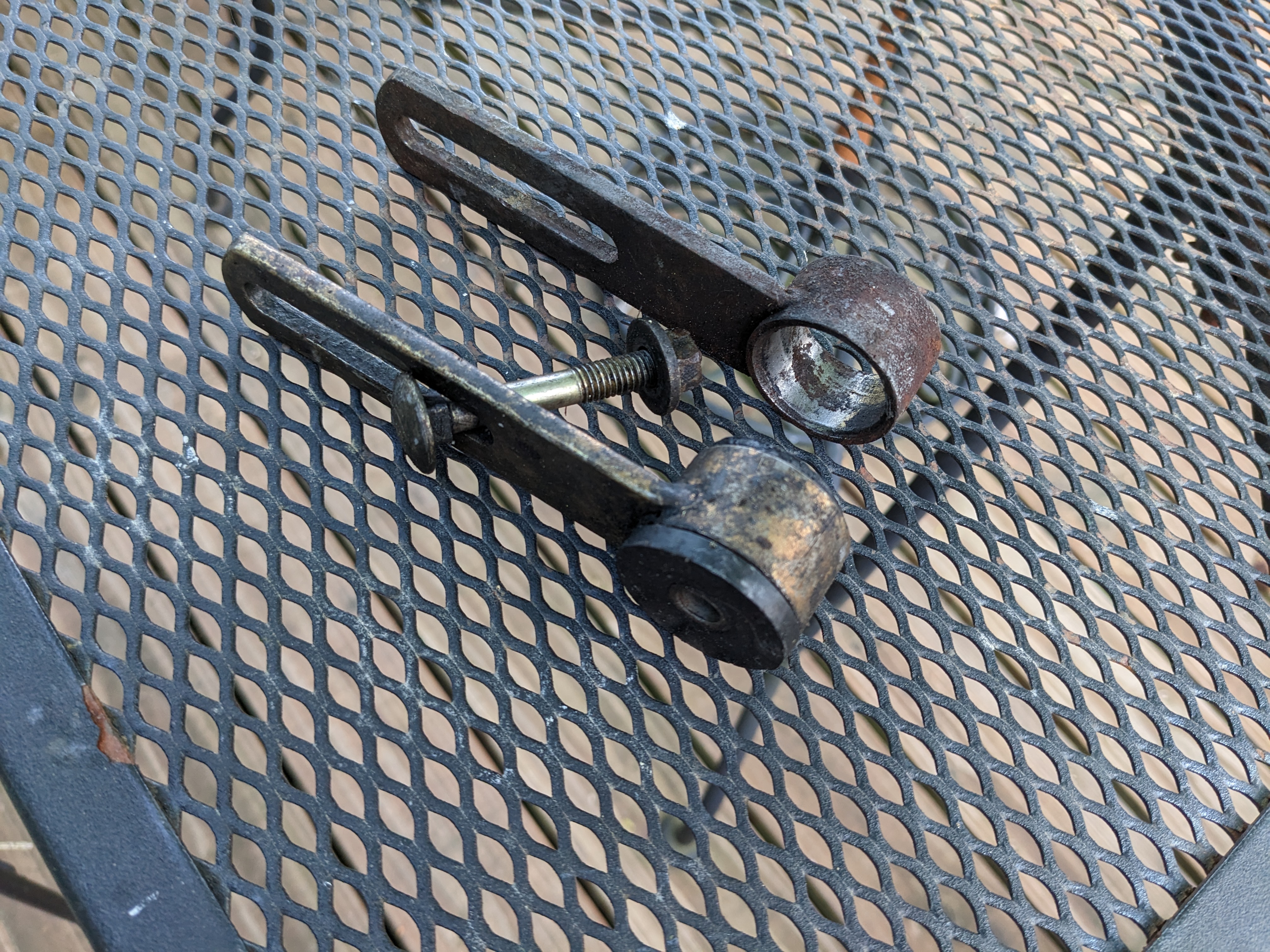
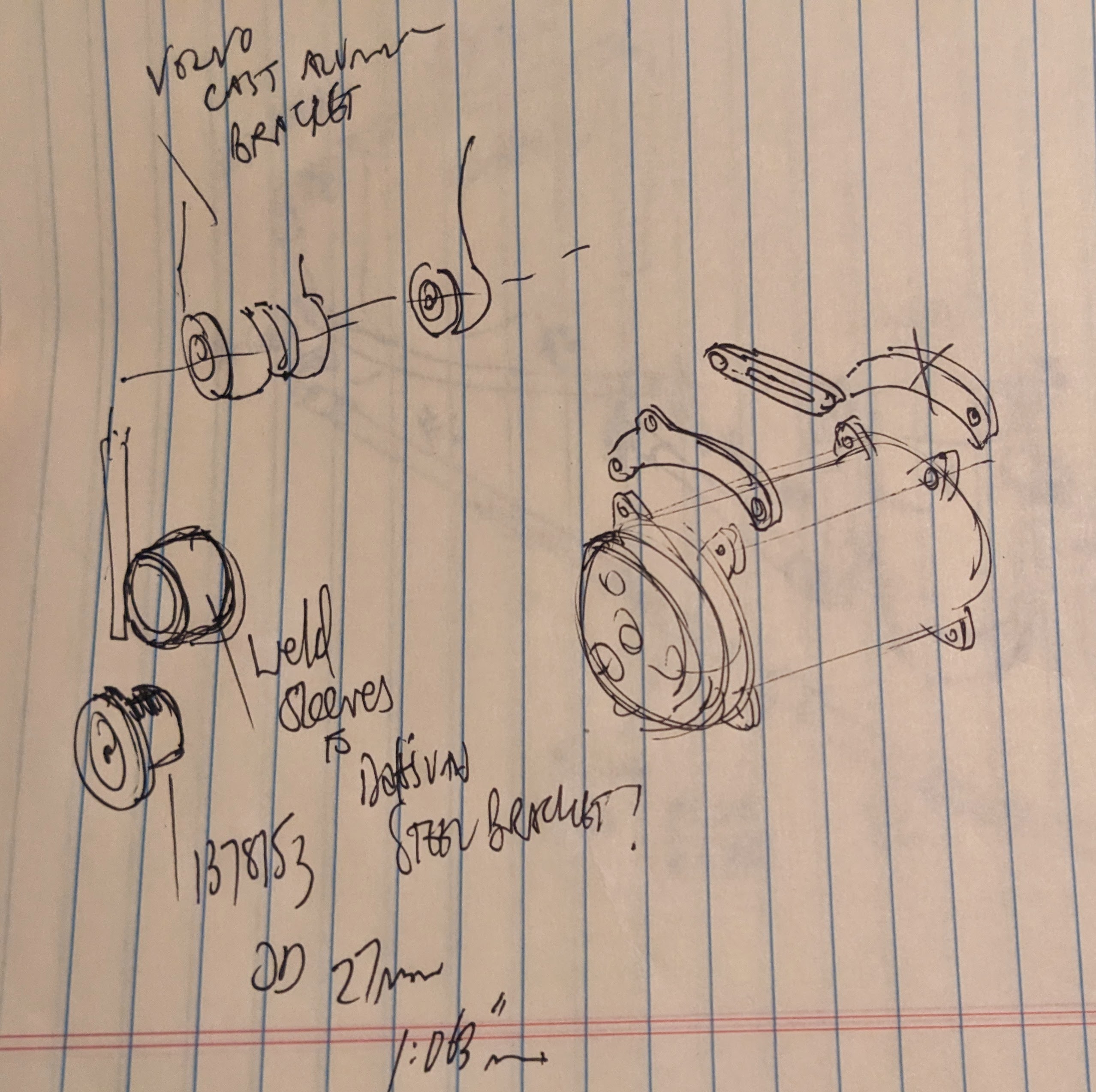
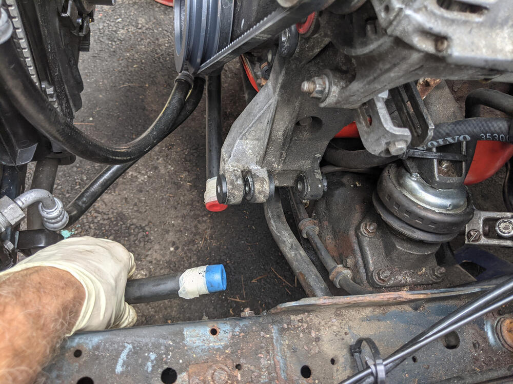
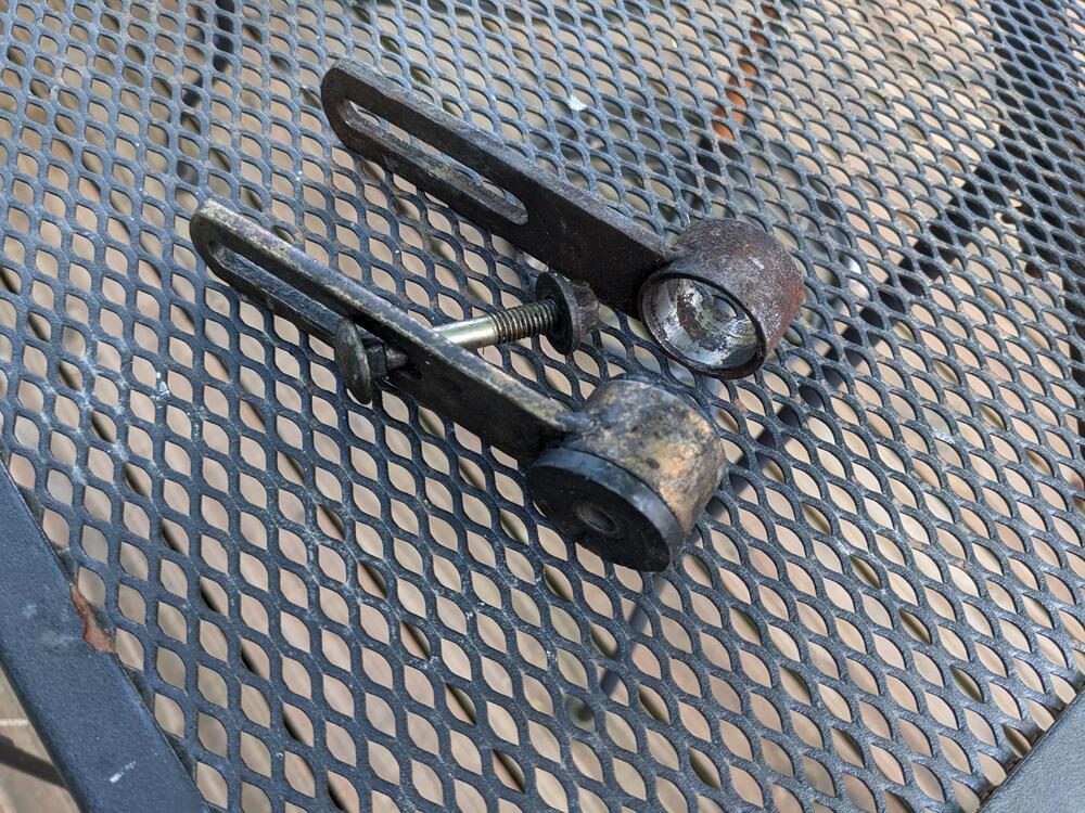
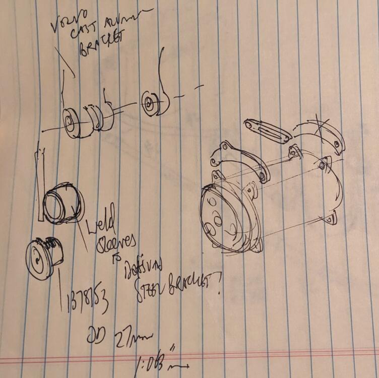
I've owned Volvos since I was a teenager. I have quite a stash of parts 🙂 I'm thinking of revising the compressor mount. Volvo setups all have rubber isolators on the pivot and adjusters to reduce vibrations. They use aluminum mount brackets, which I'm not prepared to modify to fit (pic of my old Volvo 740) What I can do is weld these steel sleeves to my existing mount bracket, to match the mount design
-
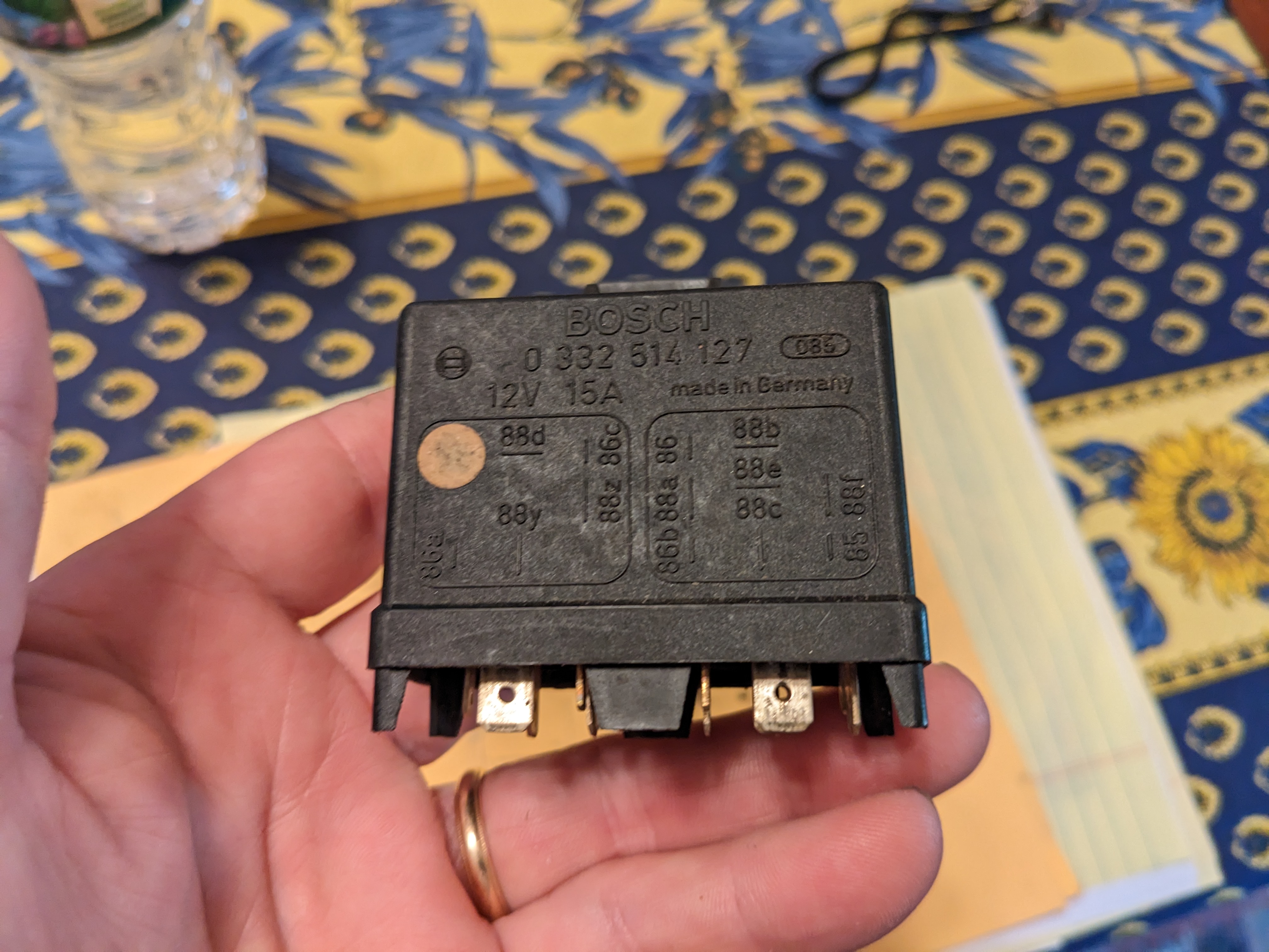
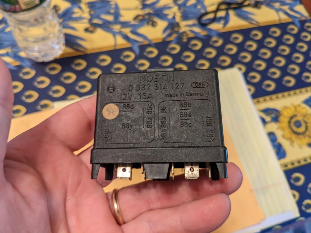
Looking at this as my 75 has the original relay with 250K miles on it... The 120 relay is no longer 'cheap' at anywhere from $170 on up in searches. I have the original 127 from my 87 Fiat/Bertone X1/9, but I'd hardly consider that a safe spare. I'm wondering if anyone documented the resistor value for the AFM circuit. That would be the only 'special' component required. Diodes are just diodes. The VW site linked is very informative, but does not give that info.
-
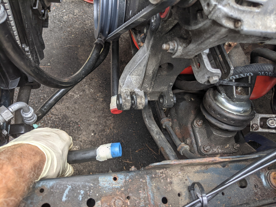
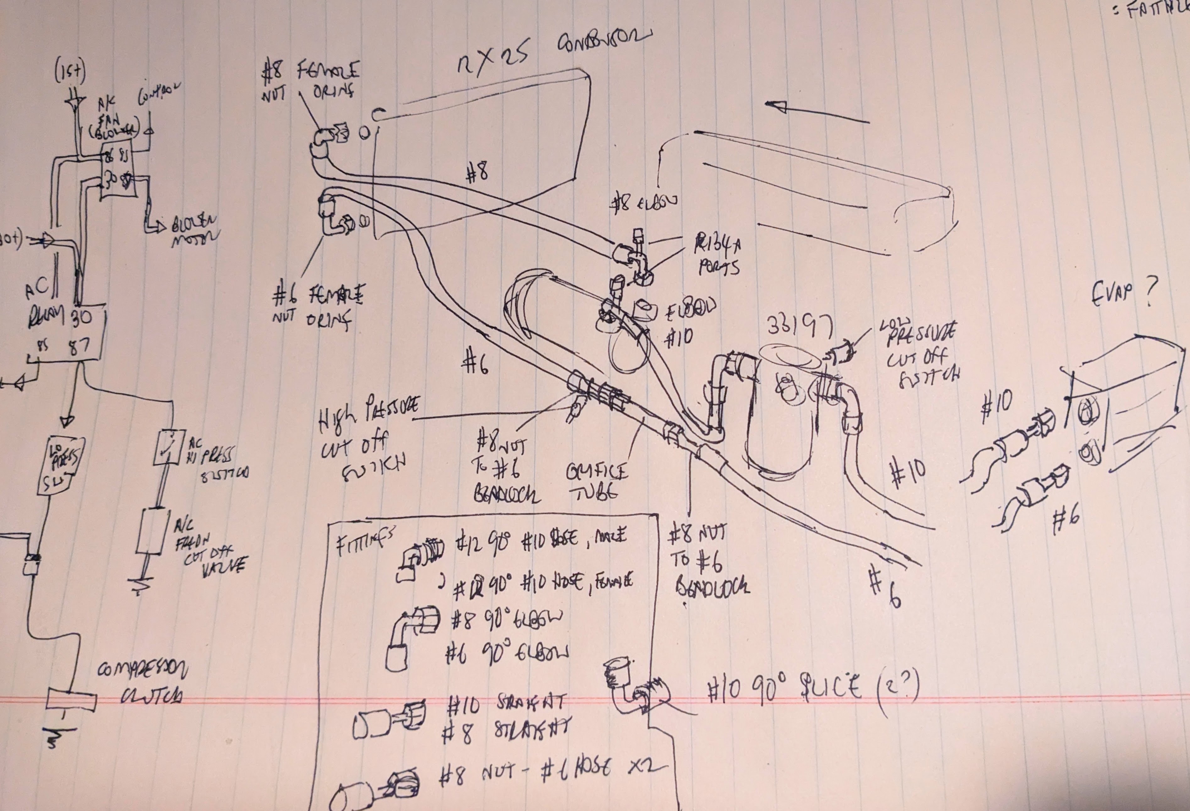
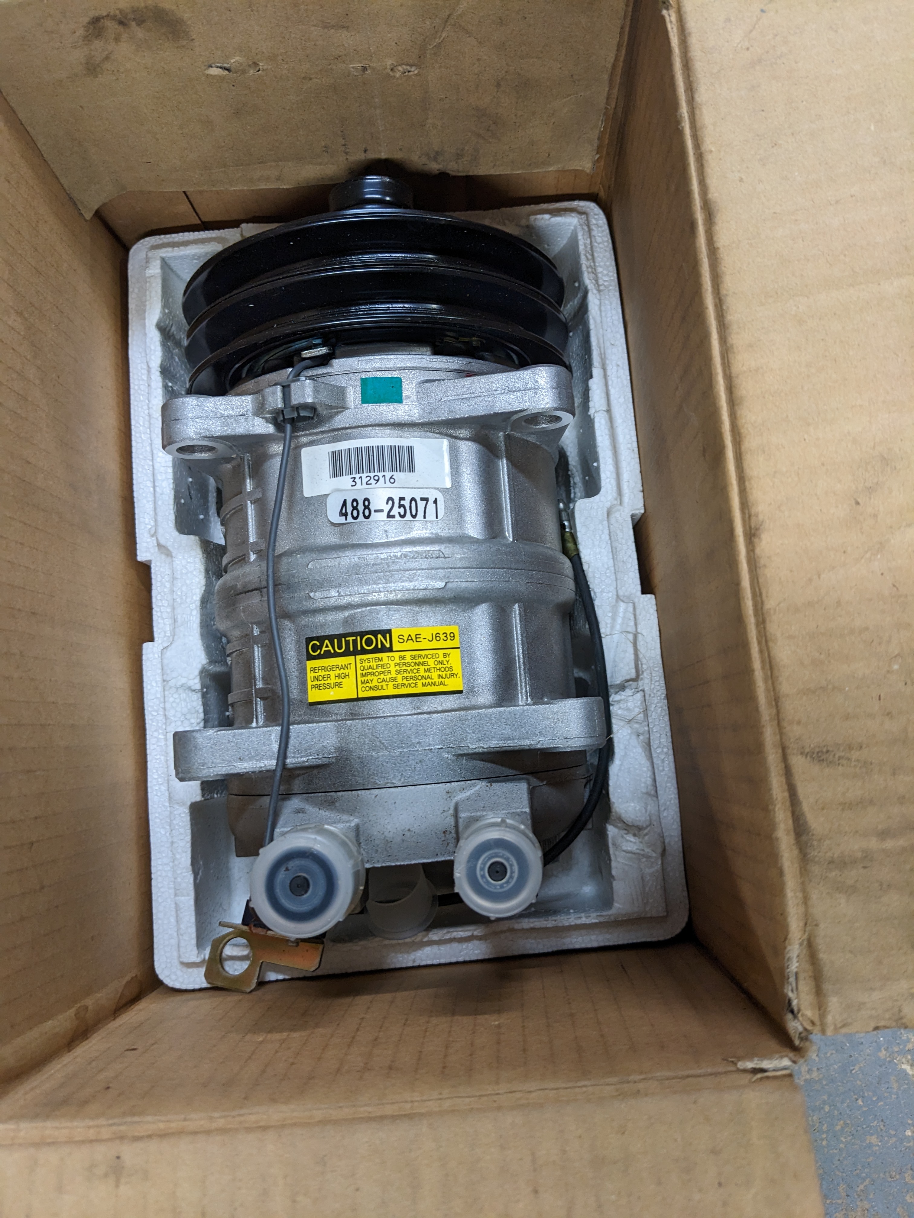
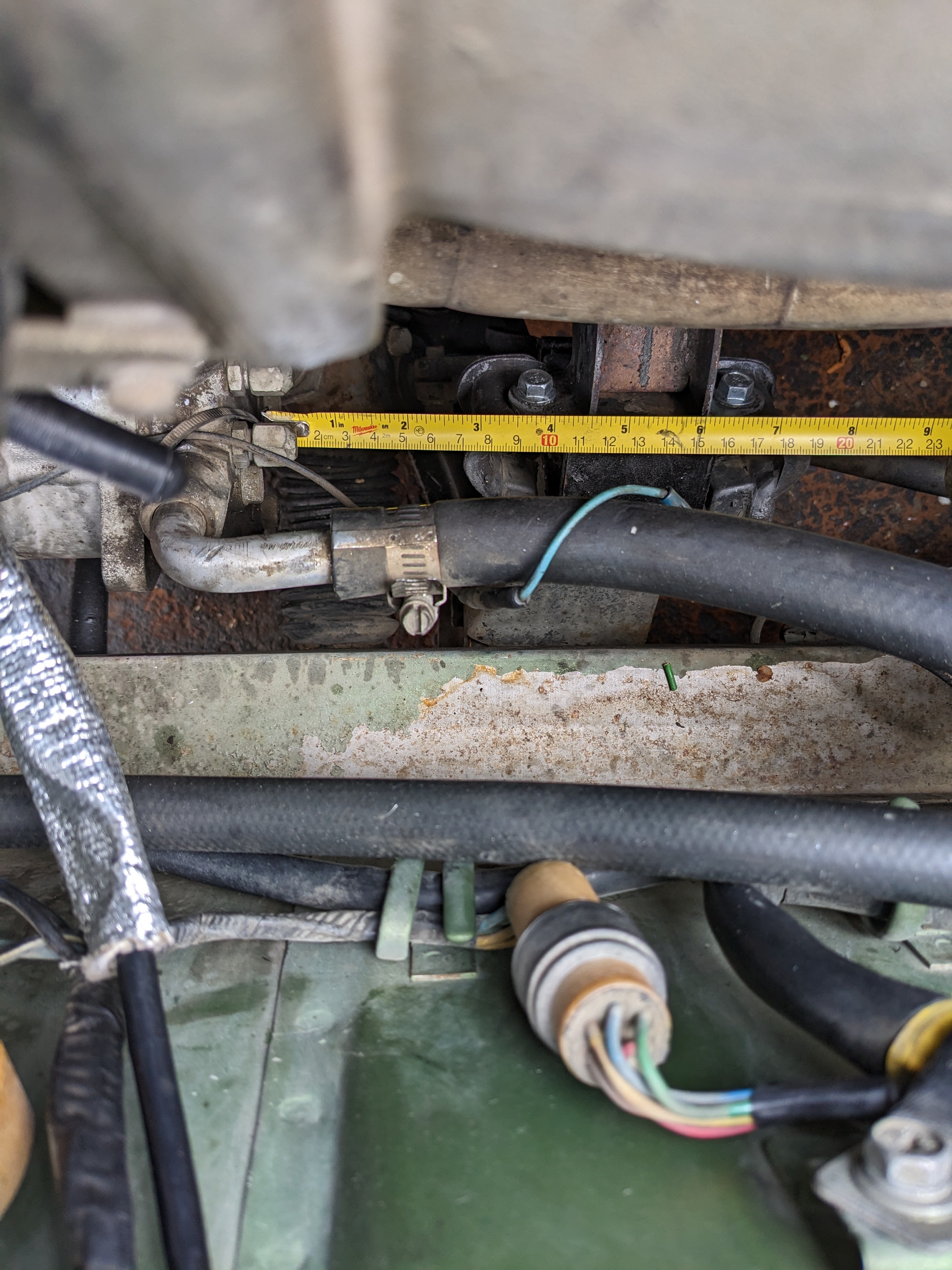
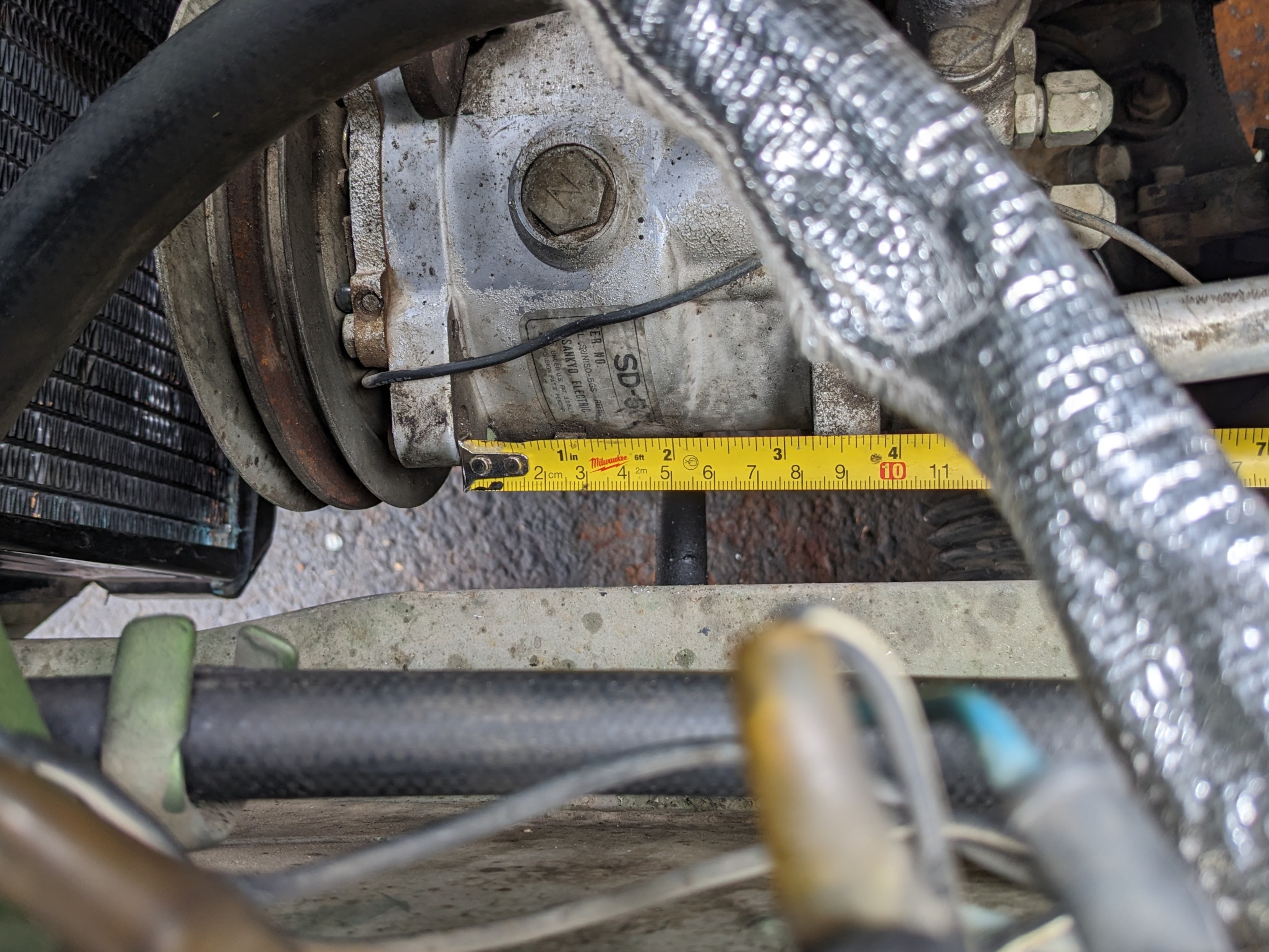
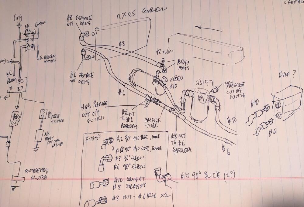
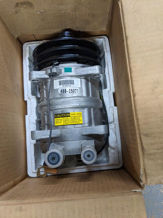
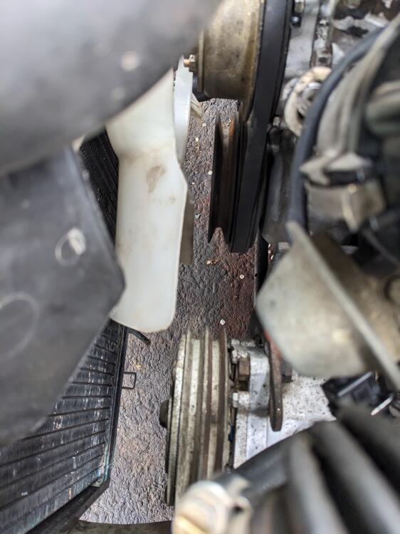
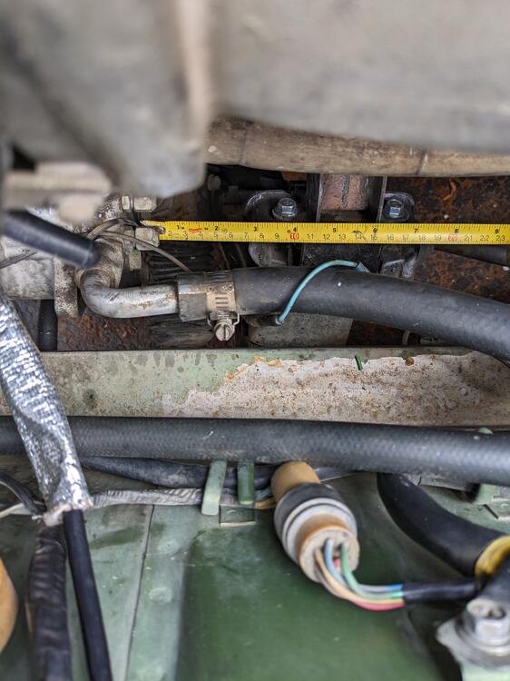
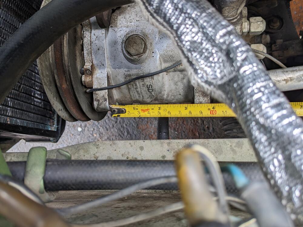
Had to sketch out the overall layout. This is following the hose routing of my dealer-installed universal/generic AC kit. This is also assuming I don't use any stock factory AC lines, which is still an option I'm considering. Once I have the dash & HVAC box apart & can see what the evaporator looks like, I can make a more informed decision on that. Seltech compressor, this one was specifically sold for Volvo 240 & 740 series cars. I'm going to modify the steel mount bracket on mine to move the compressor back. Mine uses the rear groove on the pulley. The compressor was one of the reasons I could fit the eFan/shroud, so I'm hoping I can revisit that once I have the compressor repostioned Definitely room to move the compressor back at least the inch or so needed I did forget to measure the ear spacing on the new one to compare (3.25" on the installed unit), however that is a pretty standard measurement, so hopefully it's the same or I will have more work involved in modding the mount bracket
-
Thank you - that makes the positioning & upper bracket clear. I will just have to make a mock up bracket that positions the shield at that place relative to the frame rail. As an aside, I see that the booster check valve is placed with the grey side facing the intake. On my 75, the (original) valve was also placed that way, however the arrow markings and blow-through indicate that is should be facing the opposite way. Is yours original?
-
Hopefully I will be OK with the seal depth change. That is SOP on Volvos, which can easily see way past 250K miles in service.
-
They don't provide any guide for install? It would seem to make sense to start from the speedo & tach openings to makes sure those are properly located, then stretch the leather out from there?
-
Thanks for responding. So, the lower bracket attaches to the two mount points in the frame rail (vertical surface?). Do you have any recollection of what it looks like, is it essentially an upside-down L?
-
Does anyone have pics of the brackets that tie this shield to the inner fender/frame rail, or access to the original parts catalog so I can figure them out that way? The upper tie plate appears to be relatively straight forward, going to the same location as the bay light on my 75? The lower bracket I have no idea. I want to add that shield to my 75 280Z Thanks in advance
-
280ZX is also 2.5bar? Volvo also used 2.5bar on most NA applications, but those regulators are not bolt on replacements (refer to Zed Heads earlier posts)
-
I have that one in use on my Volvo 740 (first pic). I don't recall being able to drop it below 3bar. I'll have to try it at some point to verify.
-
Thanks for the link, Steve. Unfortunately, beyond mentioning that the Ford Taurus fan/shroud can/should work, there aren't any specifics (Edit - note that in the video he is using the same Volvo fan in place of the Taurus unit). Not interested in generic/aftermarket solutions, they are always a disappointment. I've tried a range over the years on my X1/9 where eFan cooling is critical.
-
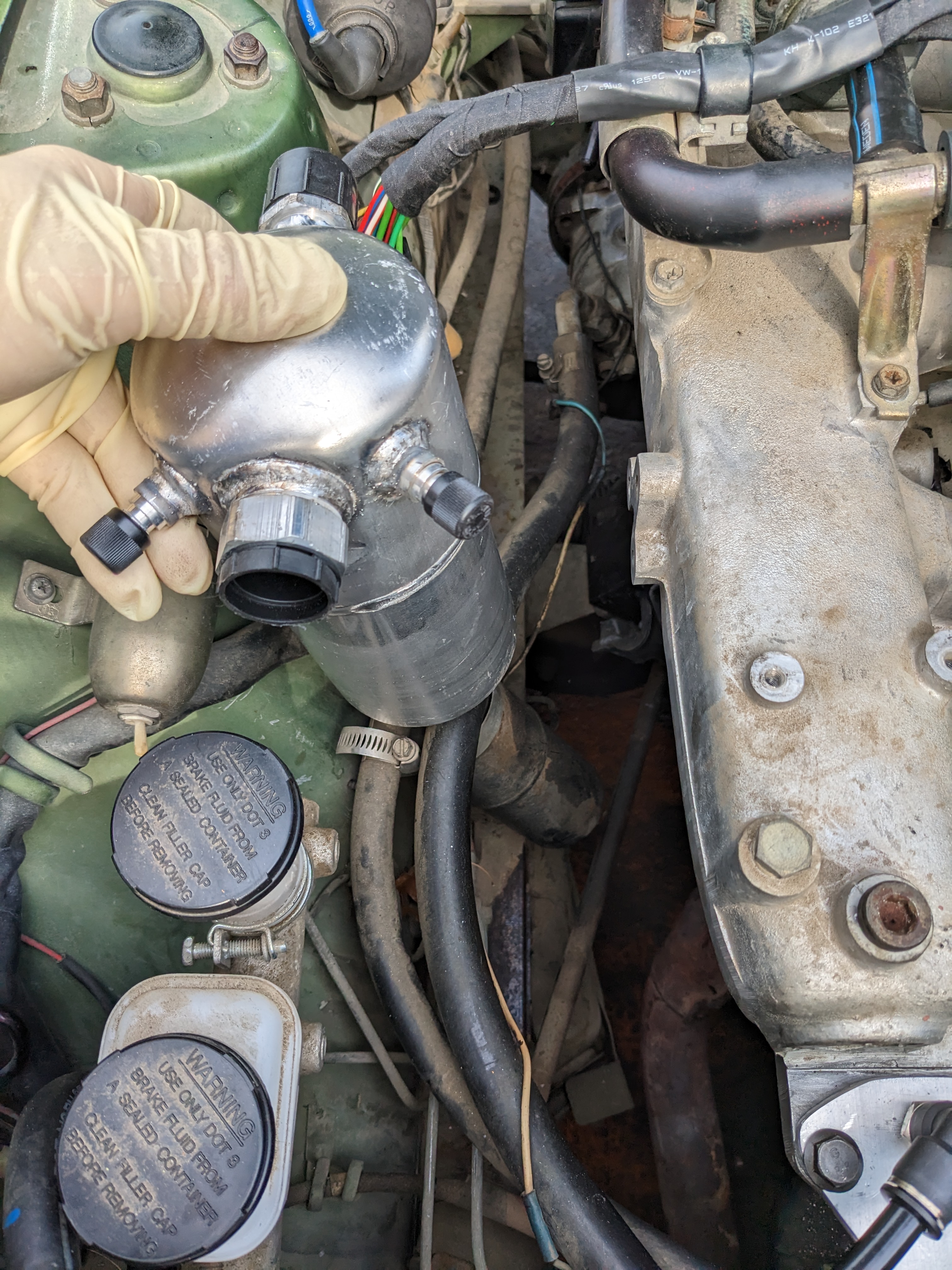
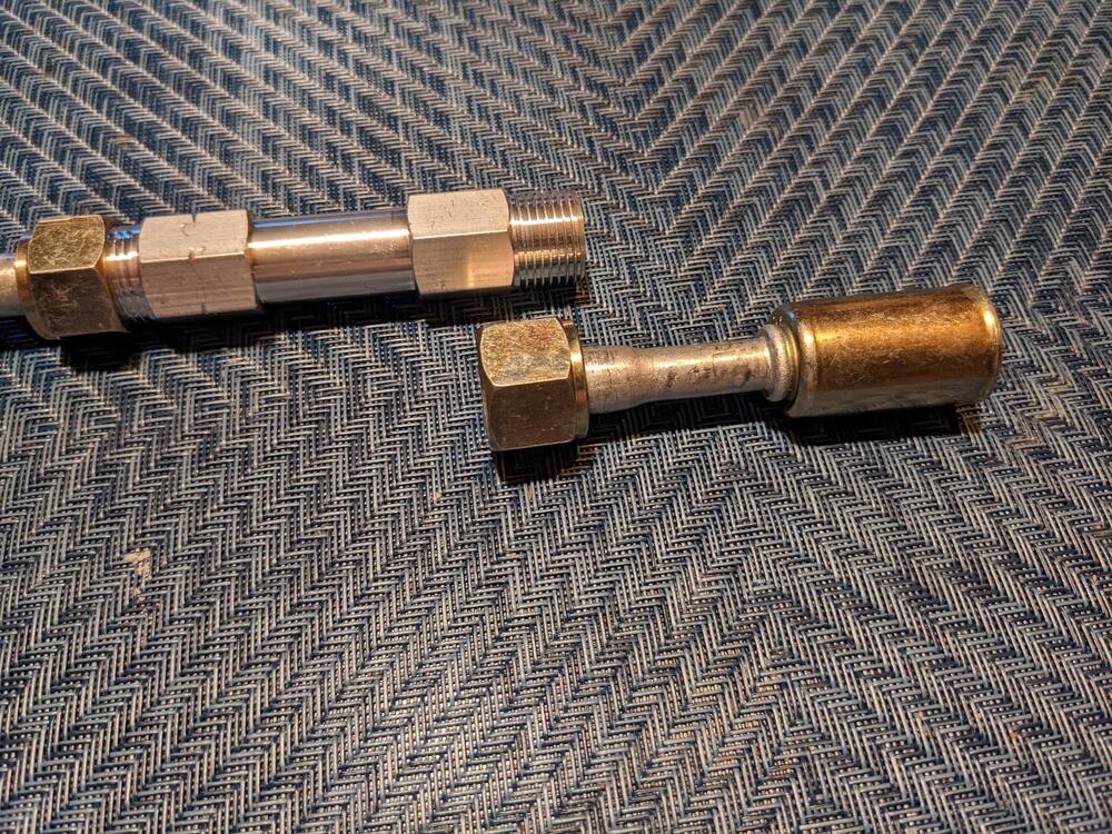
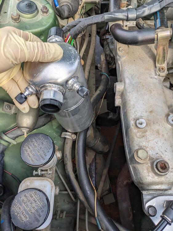
Yes, the orifice tube will be in the #6 hose from the evaporator to the condenser, in the engine bay. The expansion valve gets gutted or removed if possible. Accumulator will go pretty much where the receiver/drier was placed, but higher up. Has #12 fittings, I will step down to #10 hose. low pressure switch goes on the accumulator (Four Seasons 33197, Volvo 740 application)
-
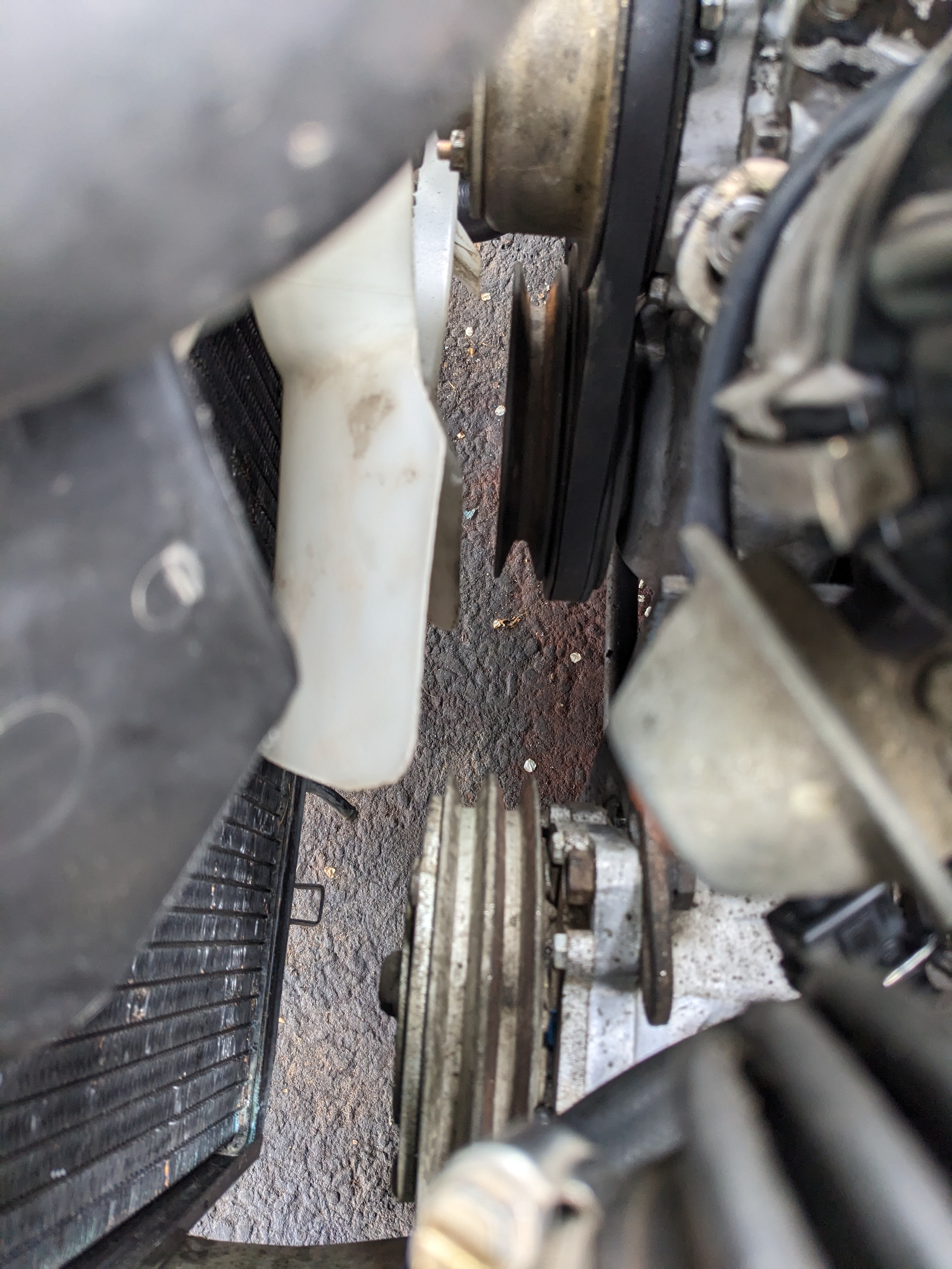
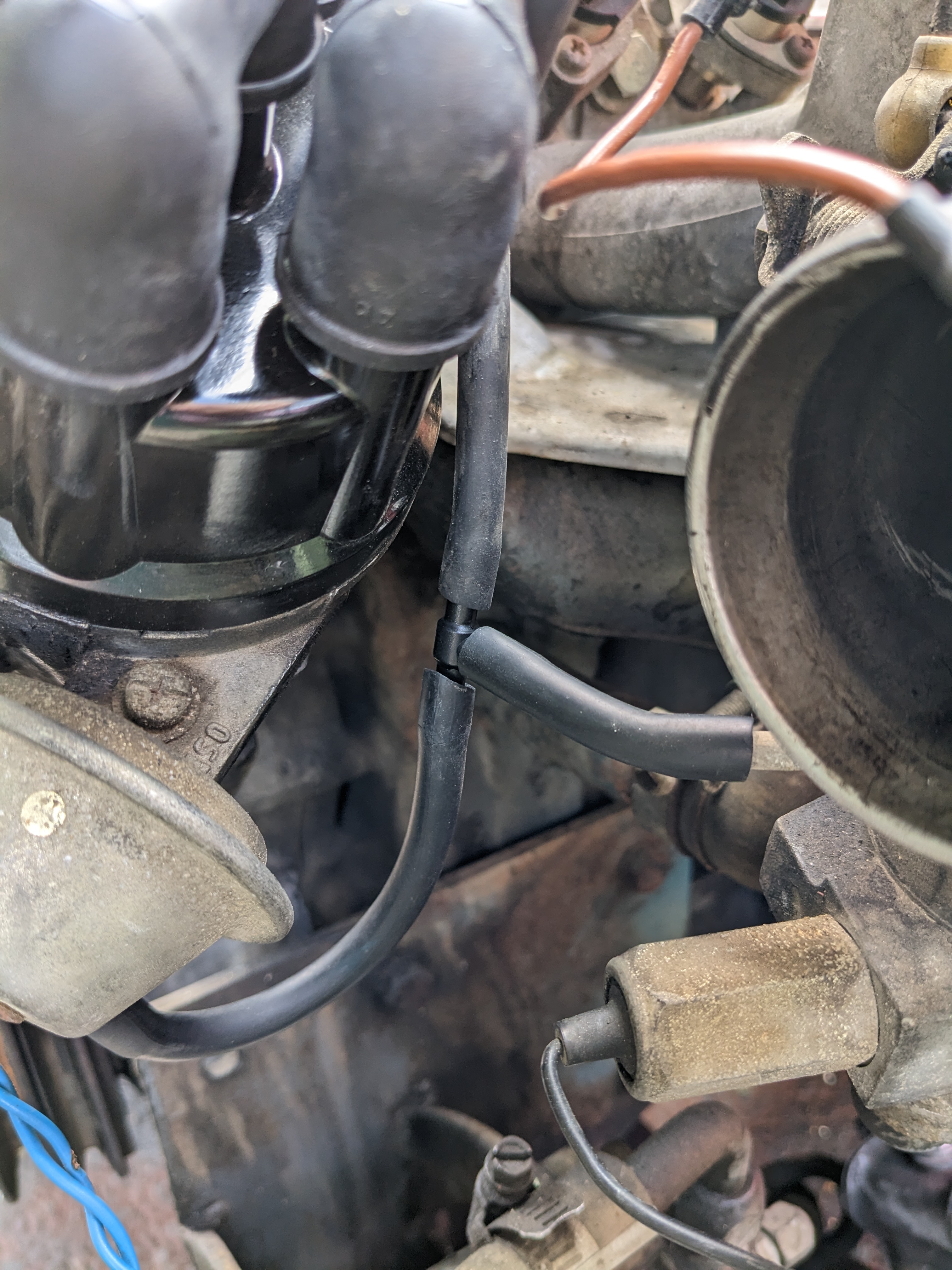
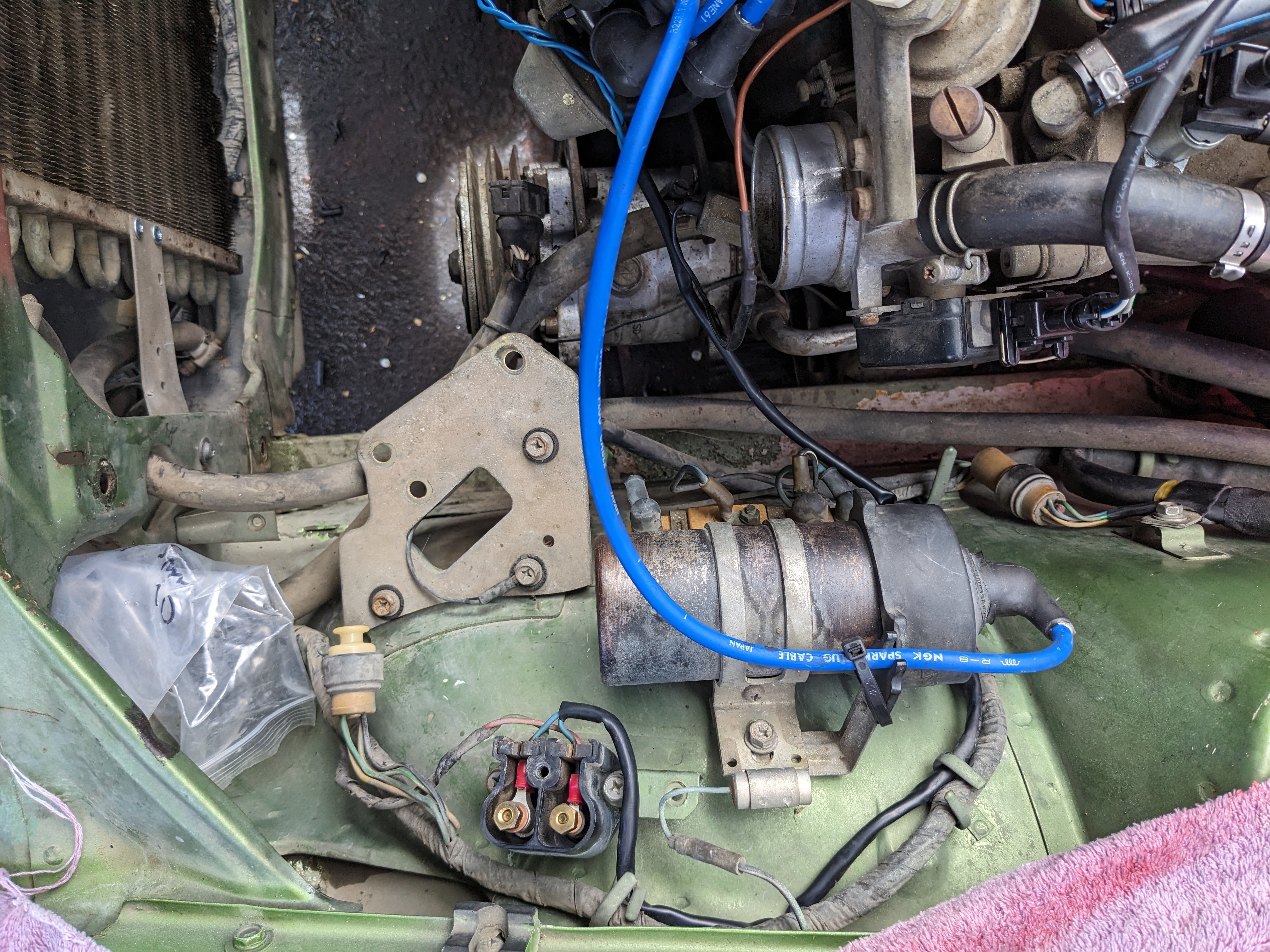
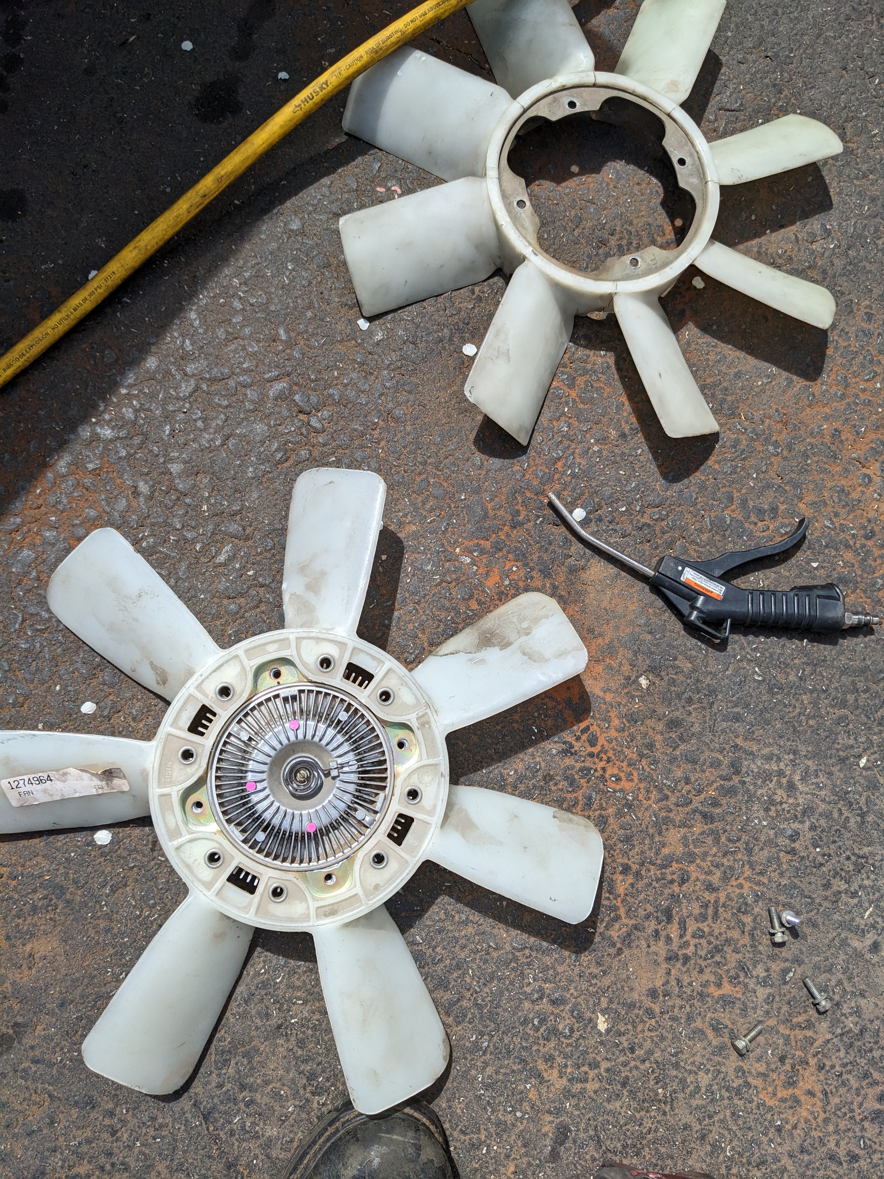
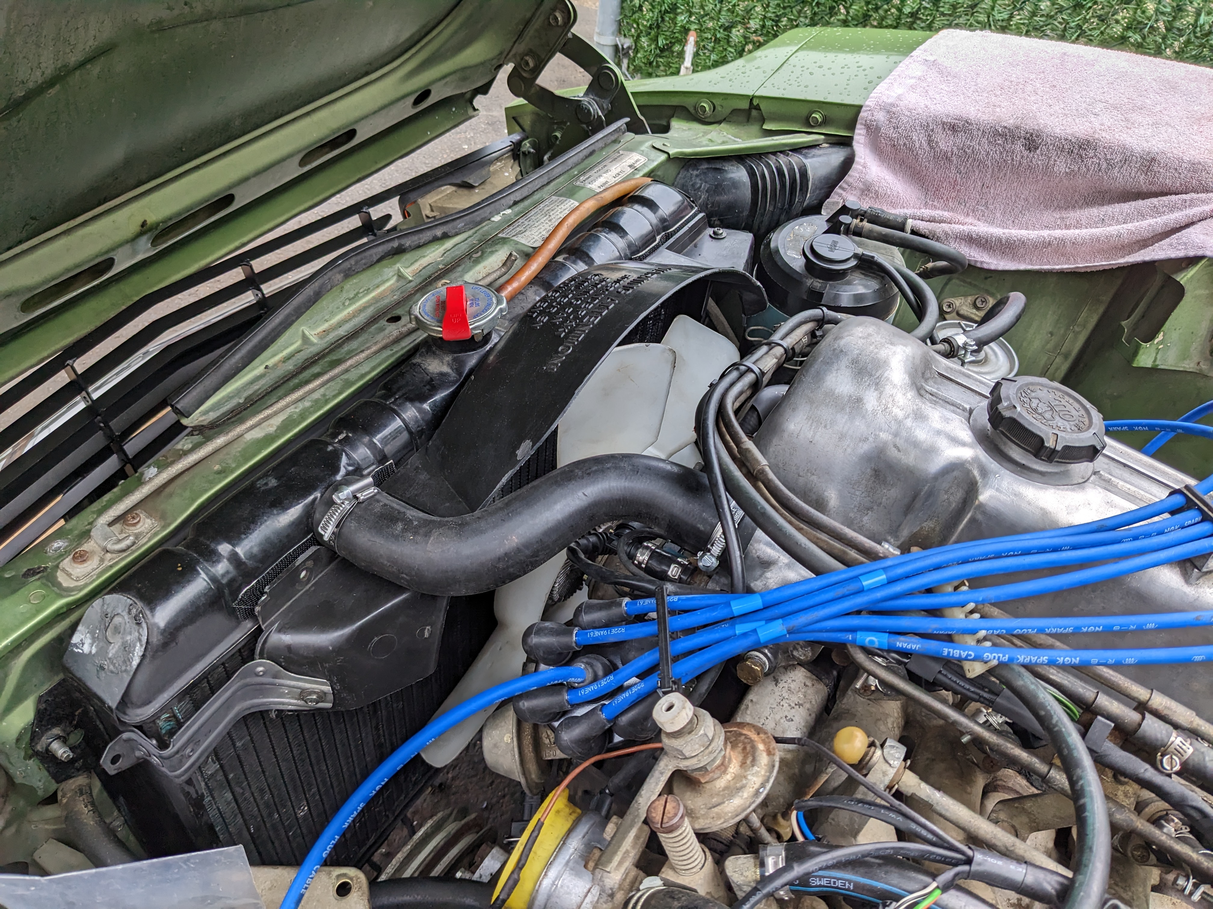
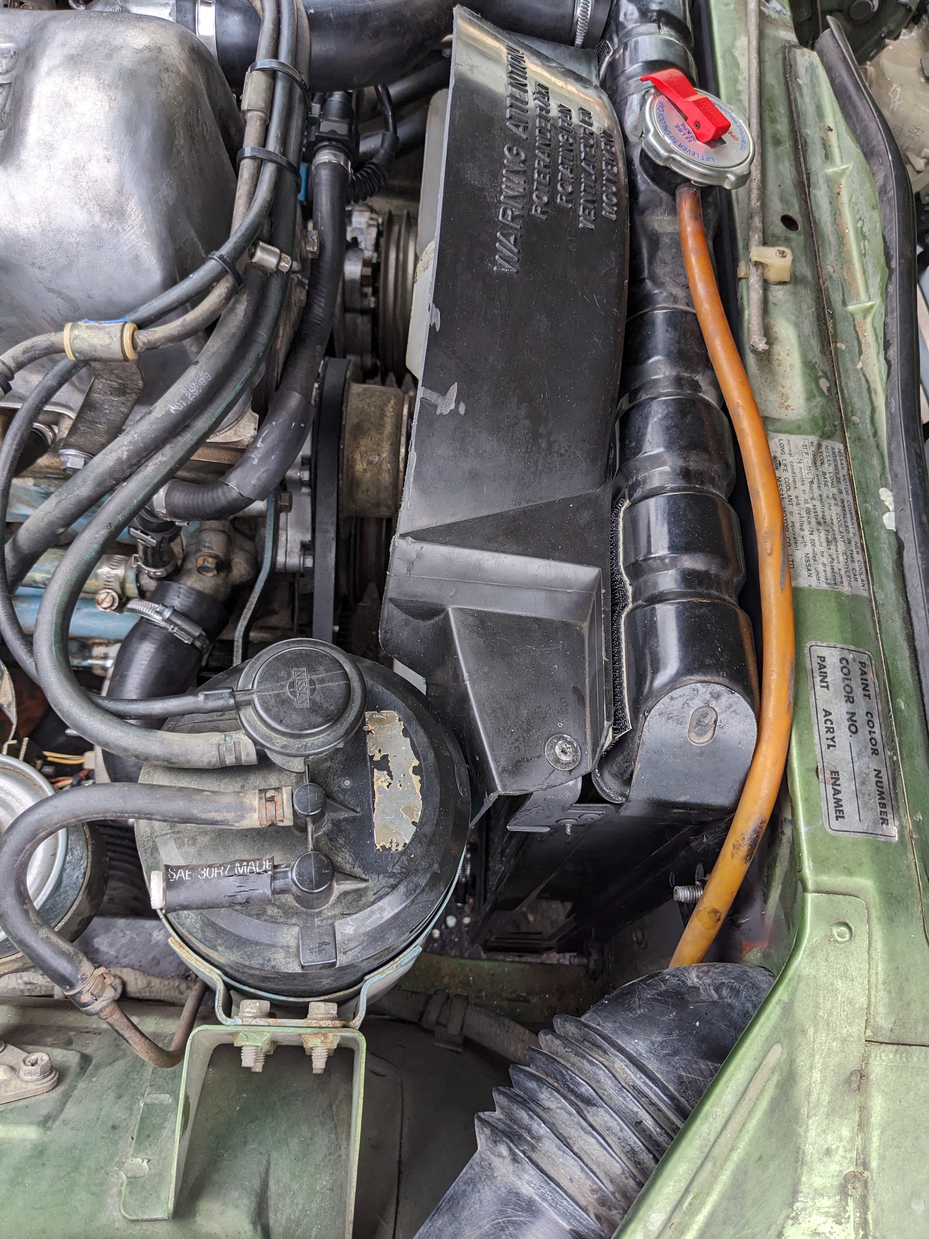
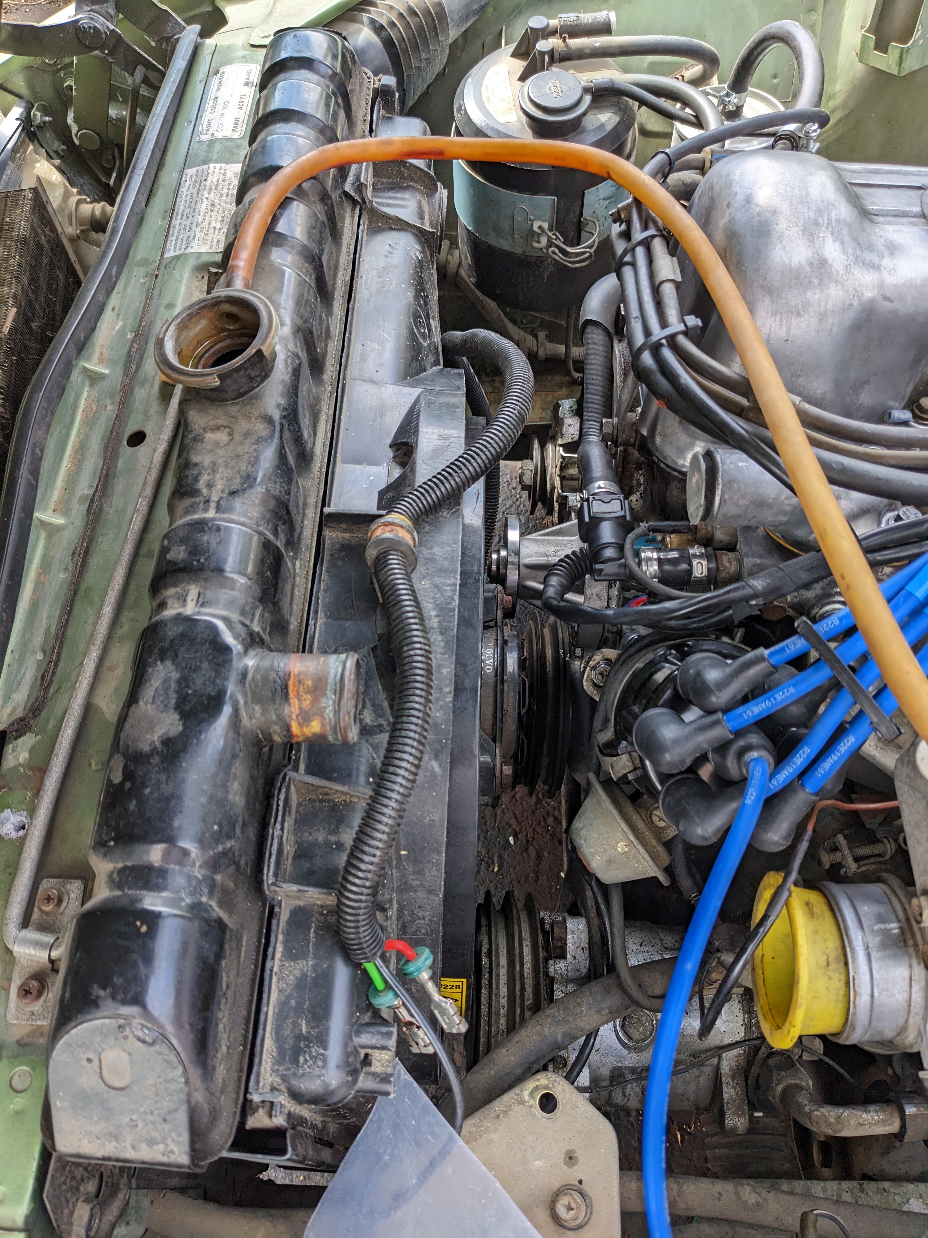
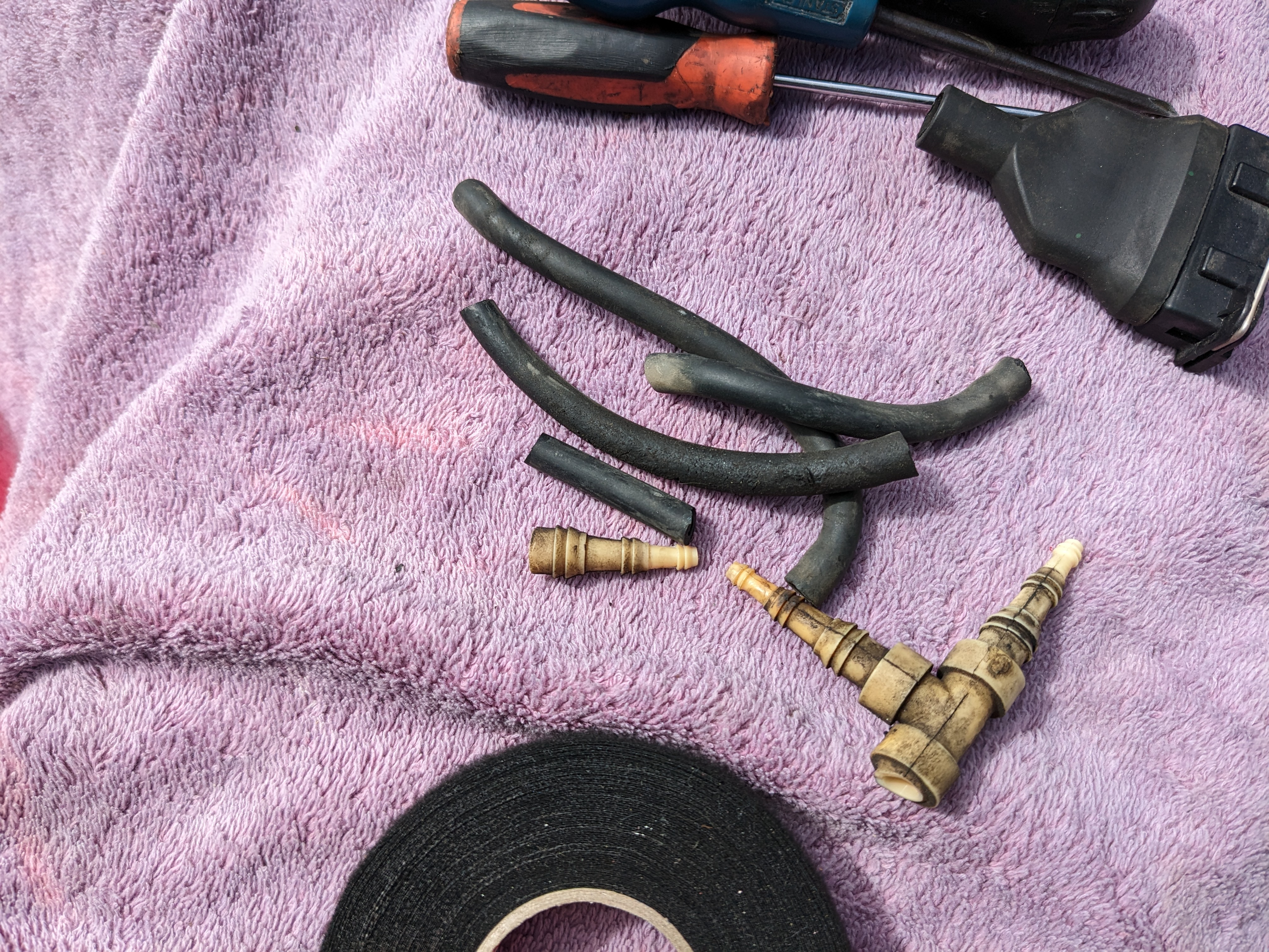
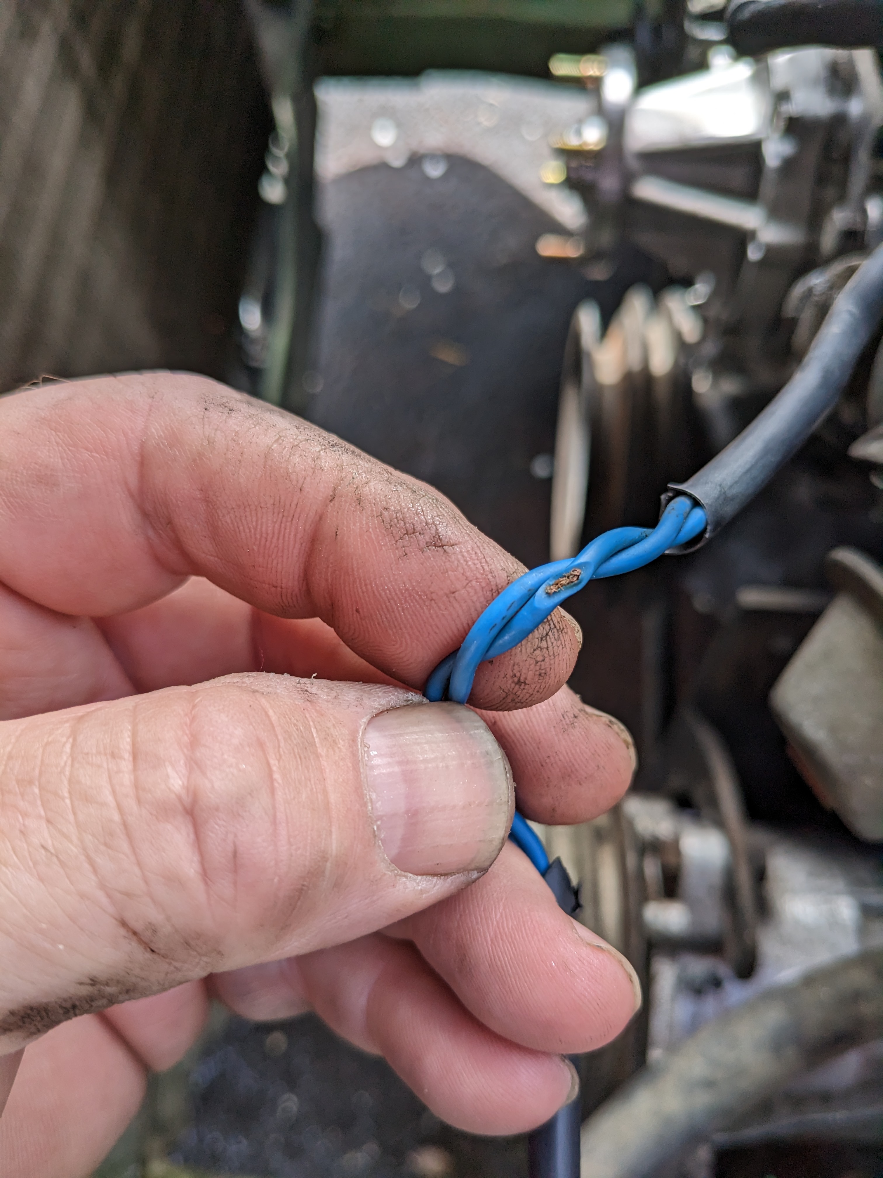
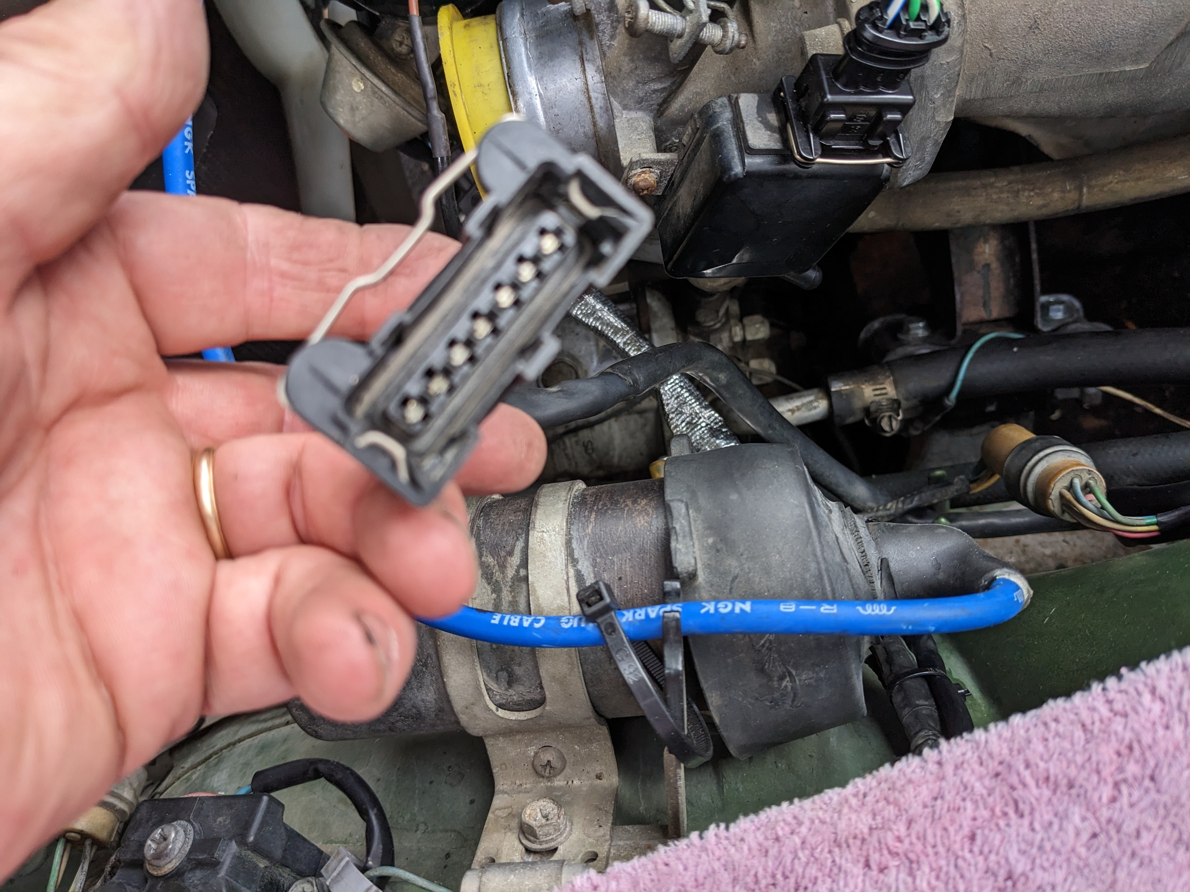
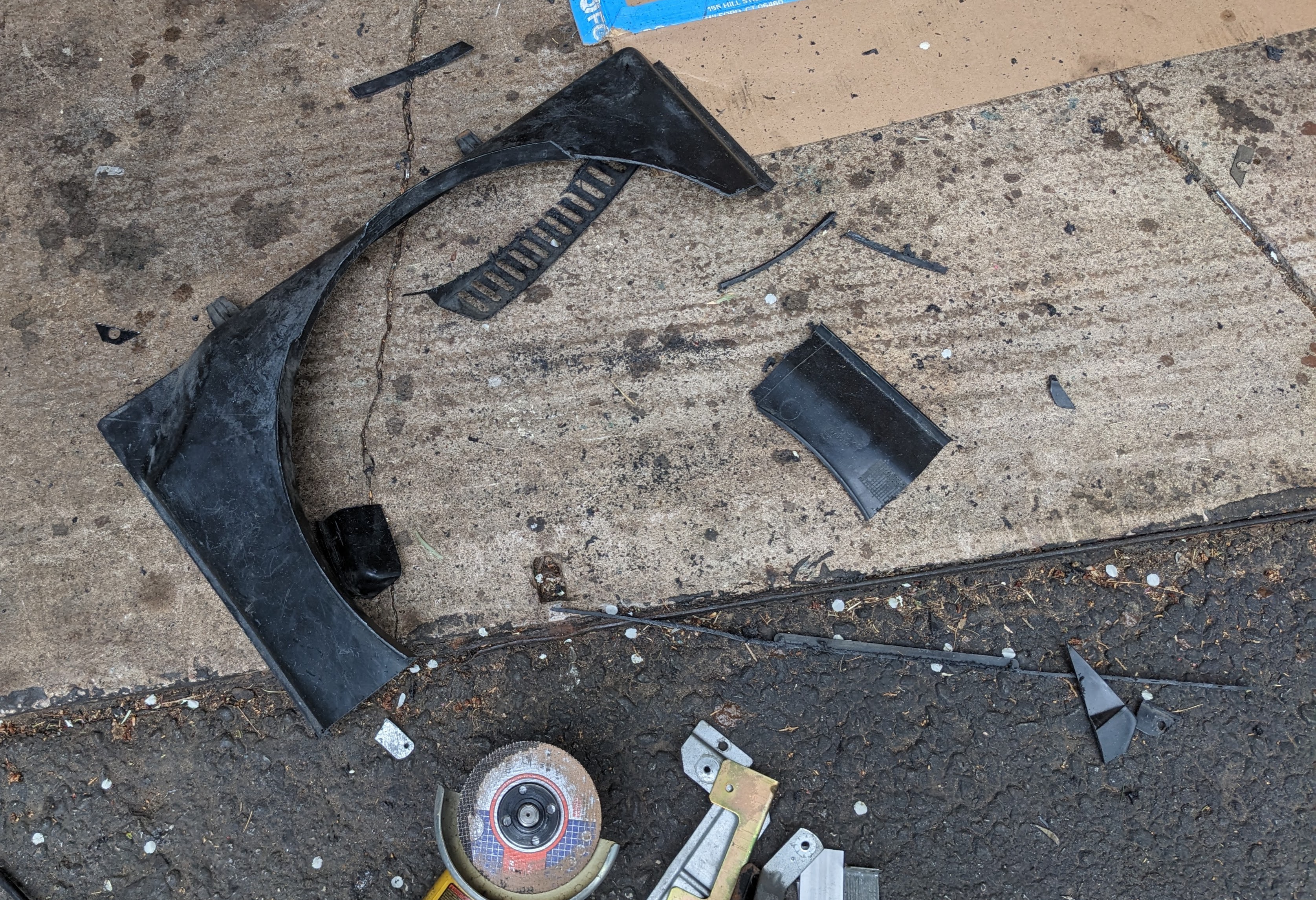
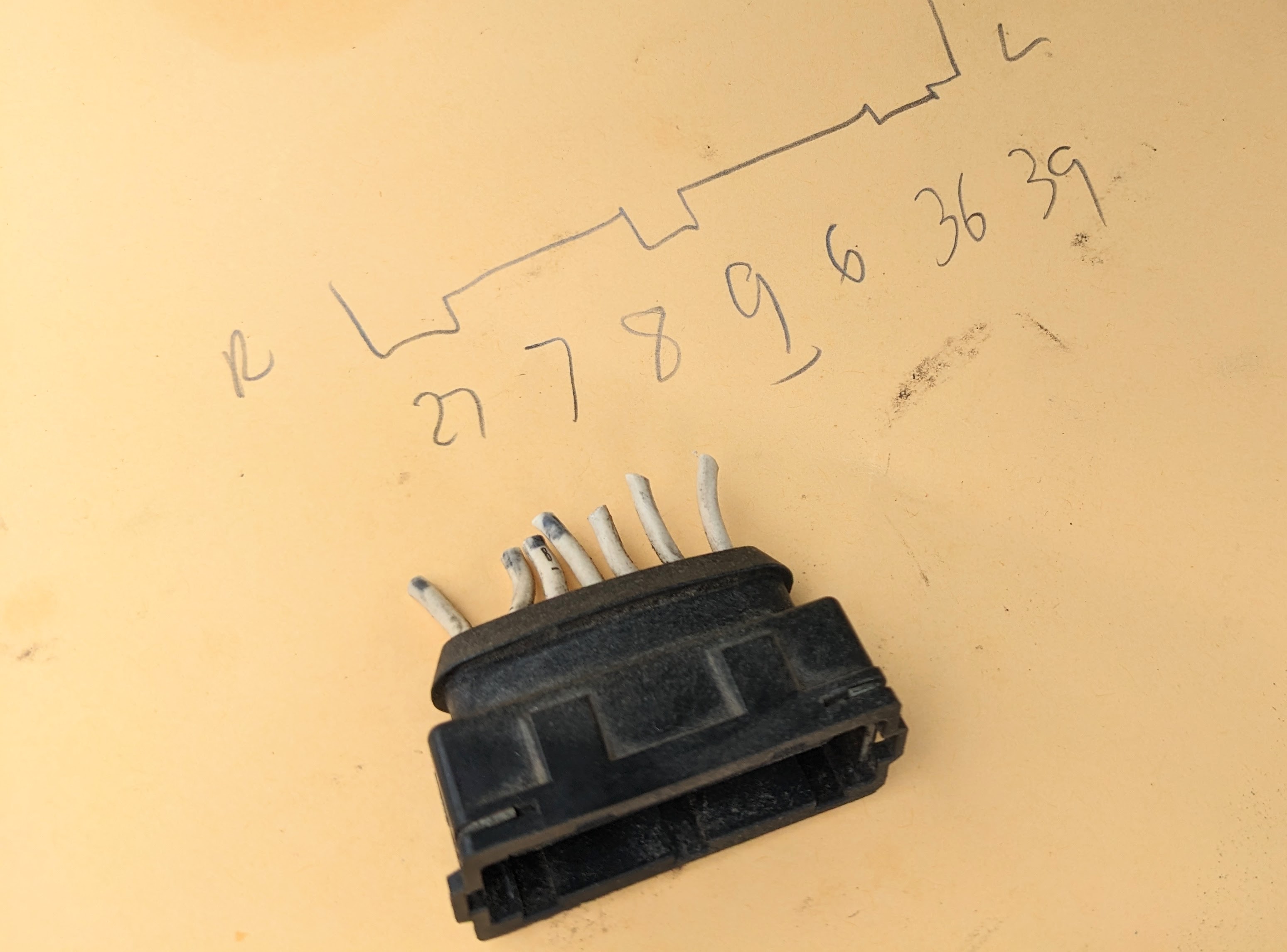
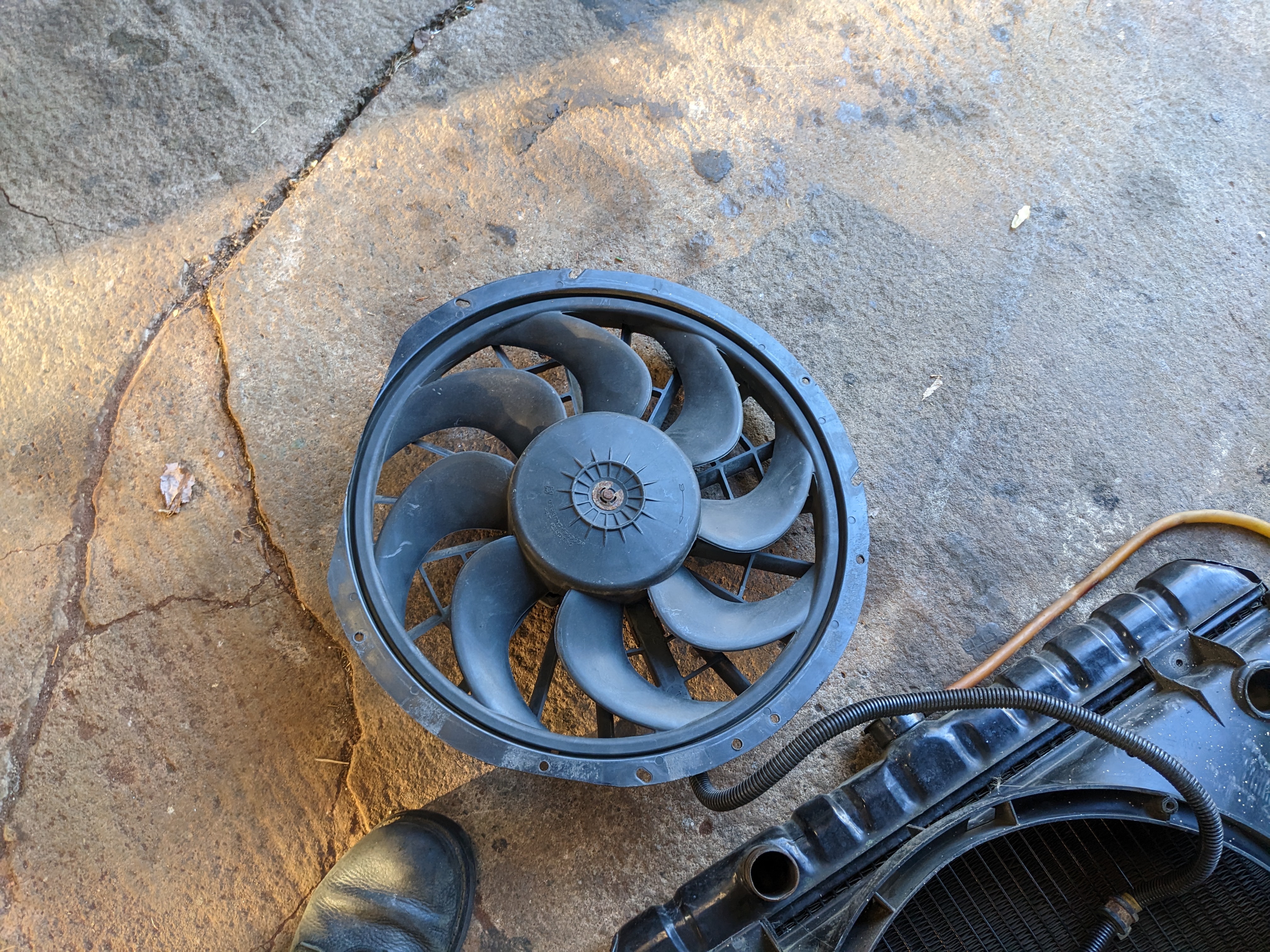
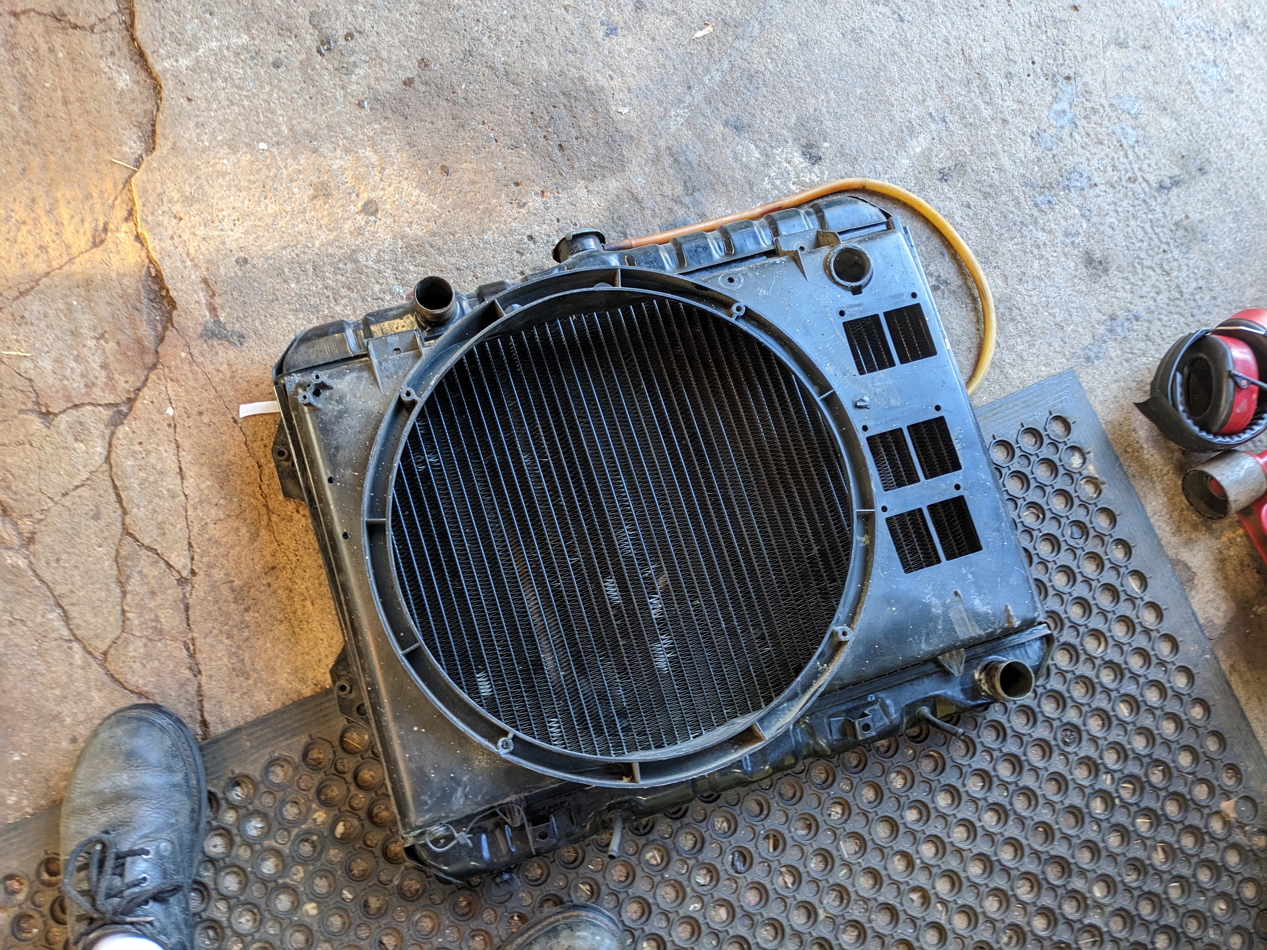
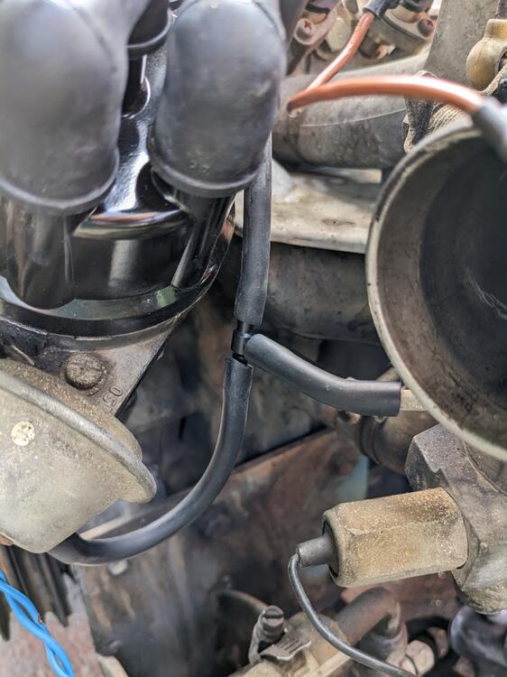
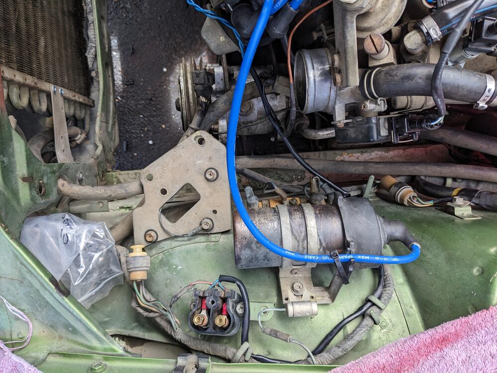
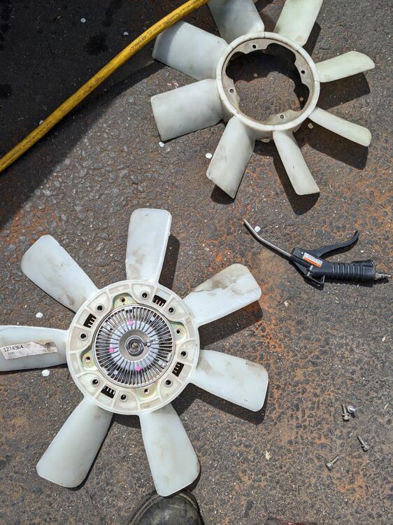
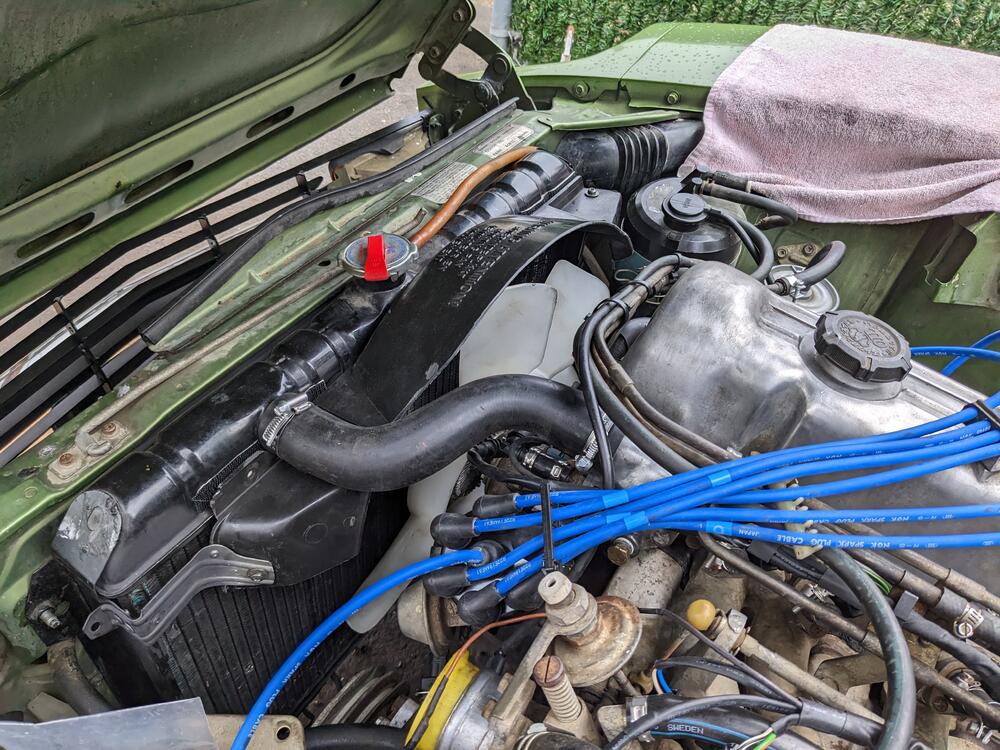
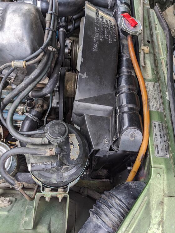
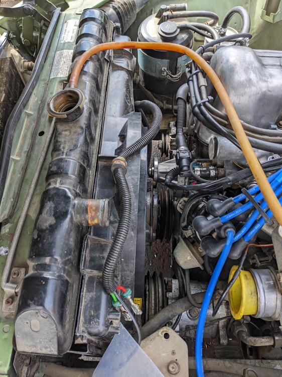
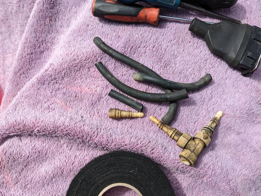
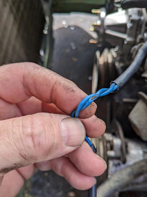
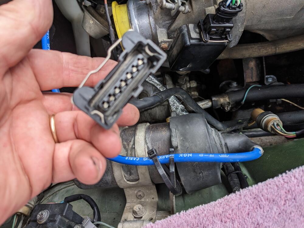
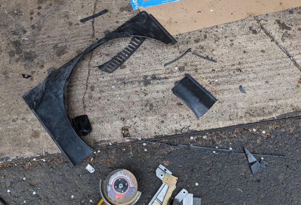
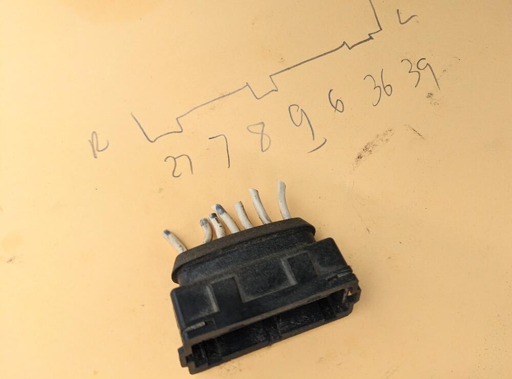
Played with the eFan. No way it's gonna work. I can't get clearance no matter what. I don't want to use an aftermarket eFan, they just don't have the pull of the Bosch units. So, I trimmed the Volvo (Aisin) fan to fit the Nissan clutch I trimmed the top half of a Volvo standard shroud to fit, I don't like the fan blade exposed. Riveted brackets to either side of the rad vertical plates to retain it ( I used 3M Velcro to hold it while I figure those out) While I was in there, I fixed the distributor vacuum line/tee connection to the TB and charcoal cannister The distributor wiring had been nicked at some point by the fan, so I re-routed that, and added a sealed 2 pole timer connection where the wire was damaged (no pic) Rewired the AFM also - blurry pic. The heat sheath below is on the dist wiring - since it is now closer to the manifold.
-
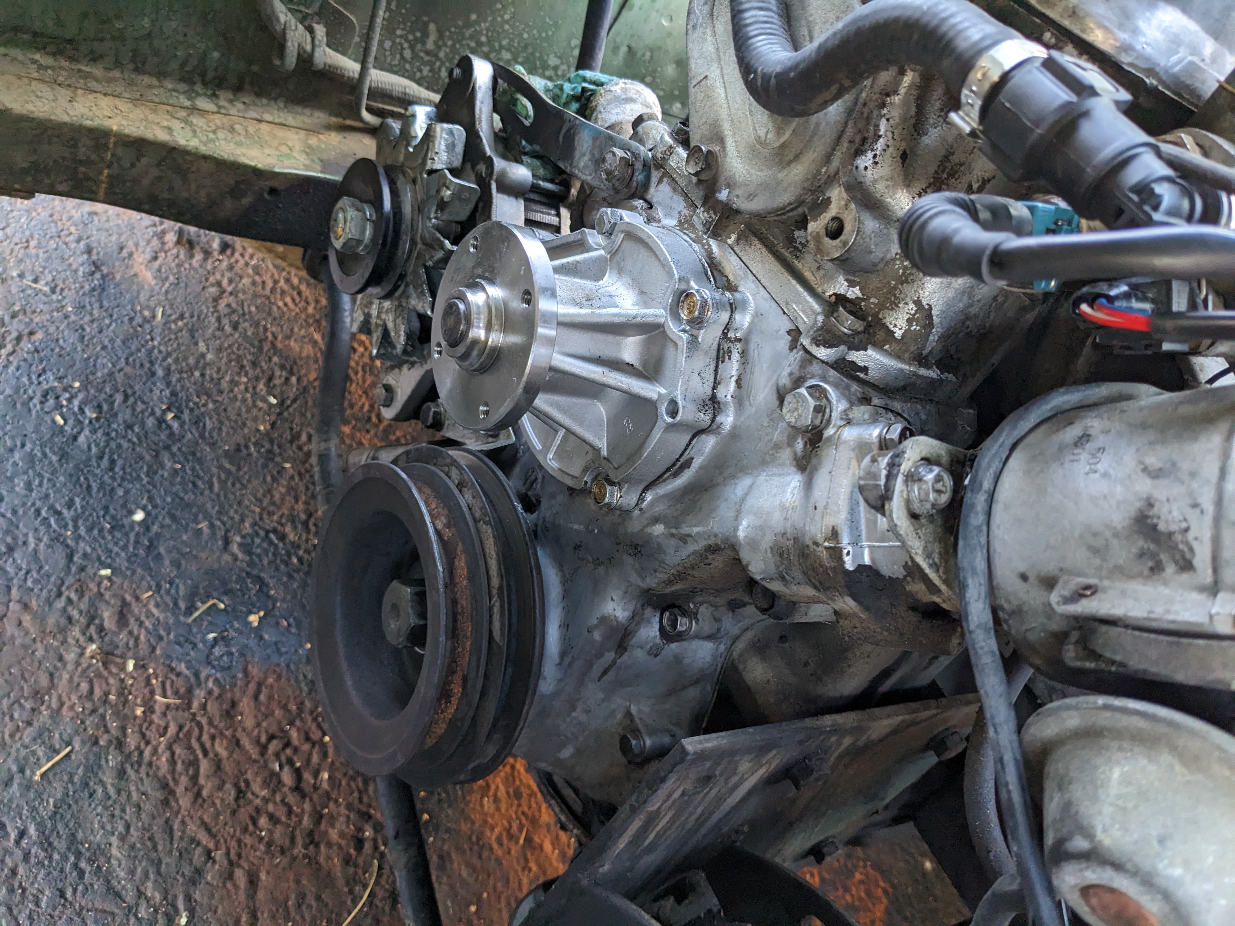
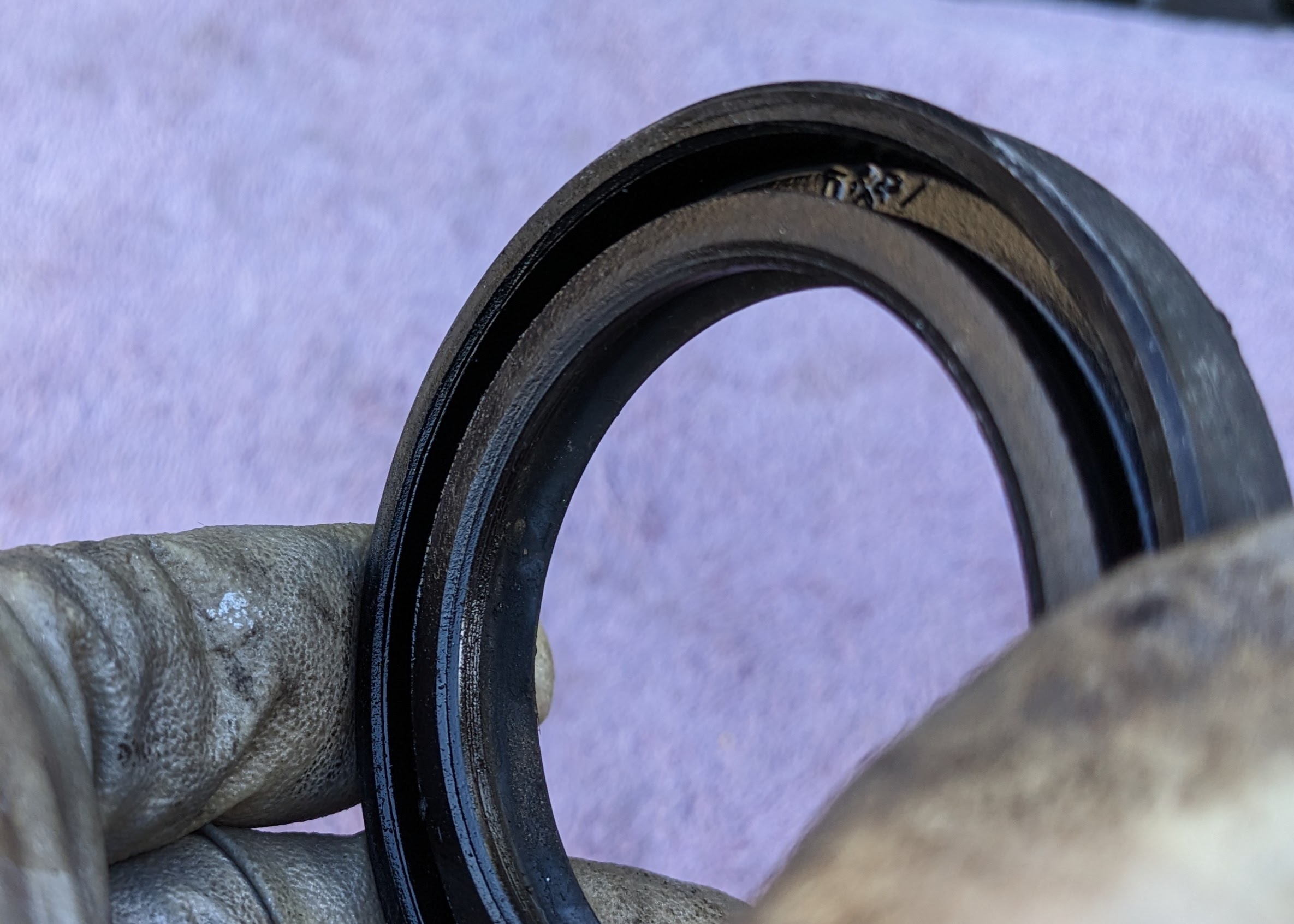
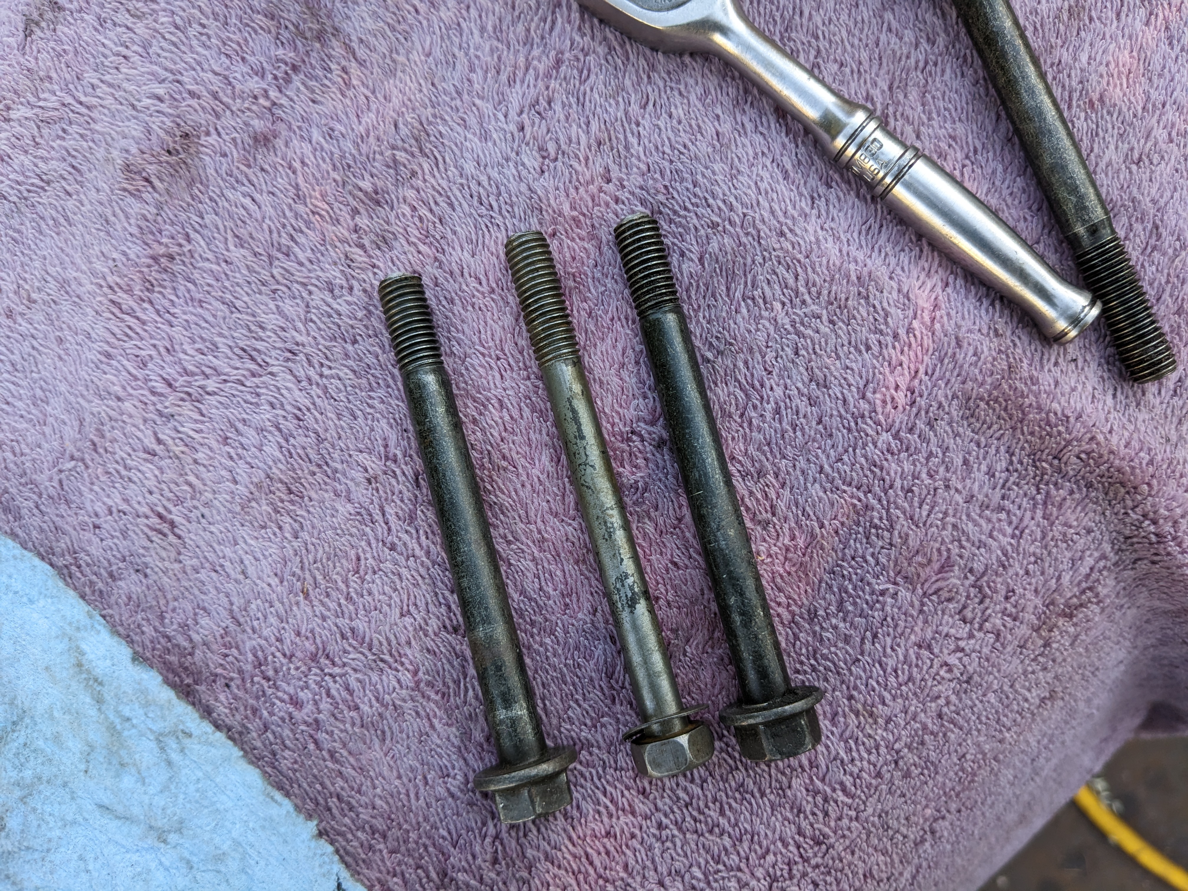
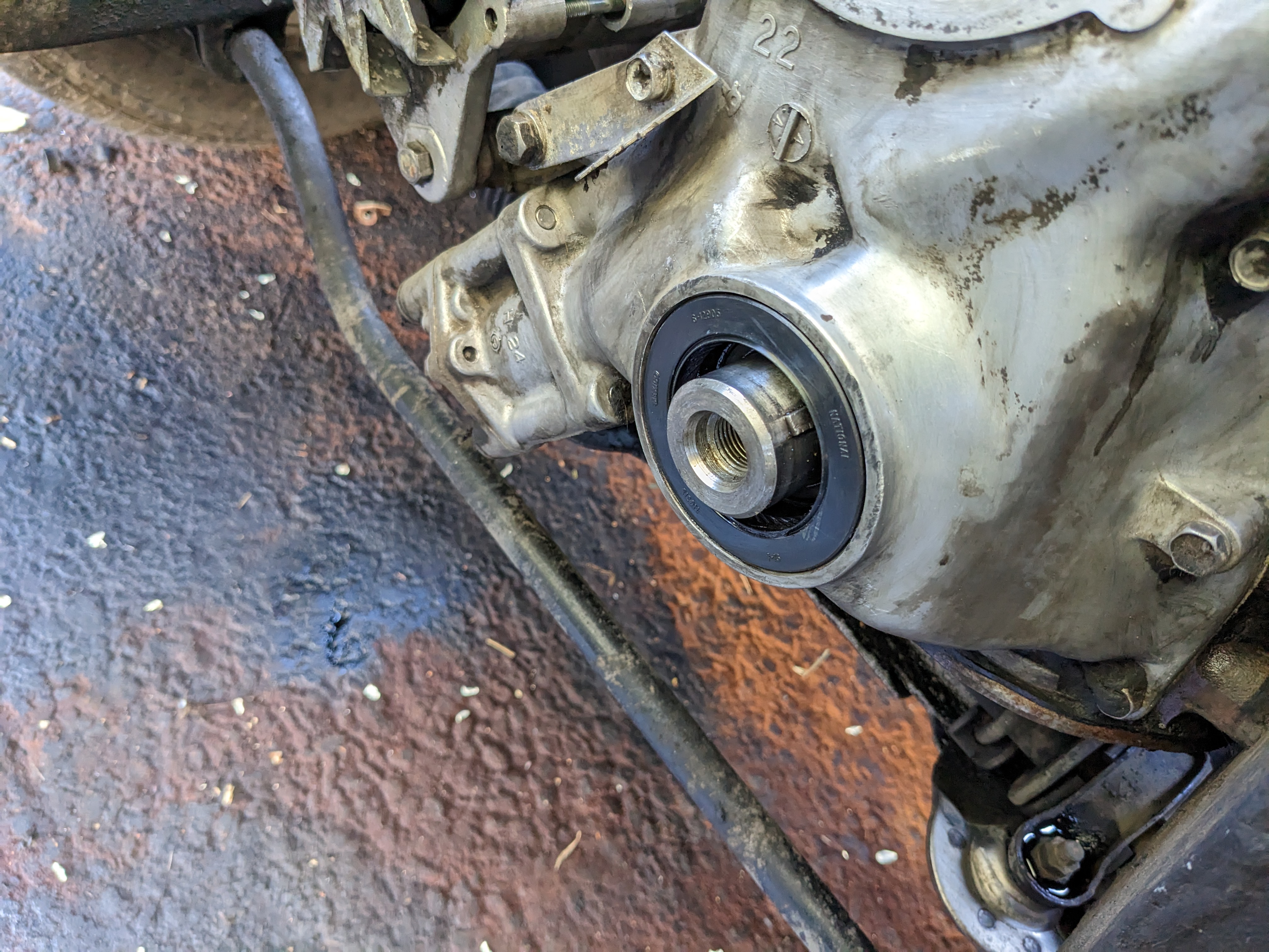
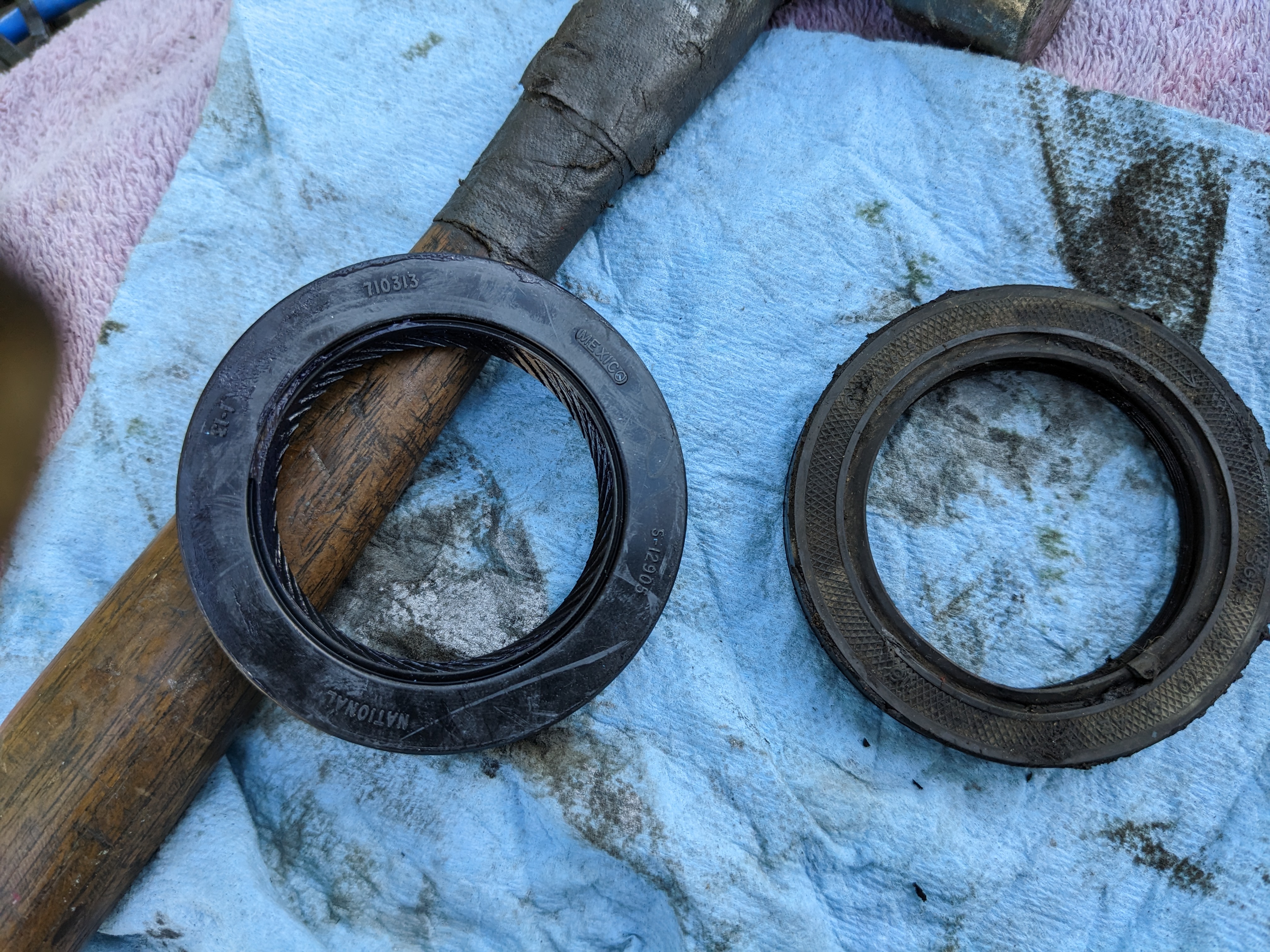
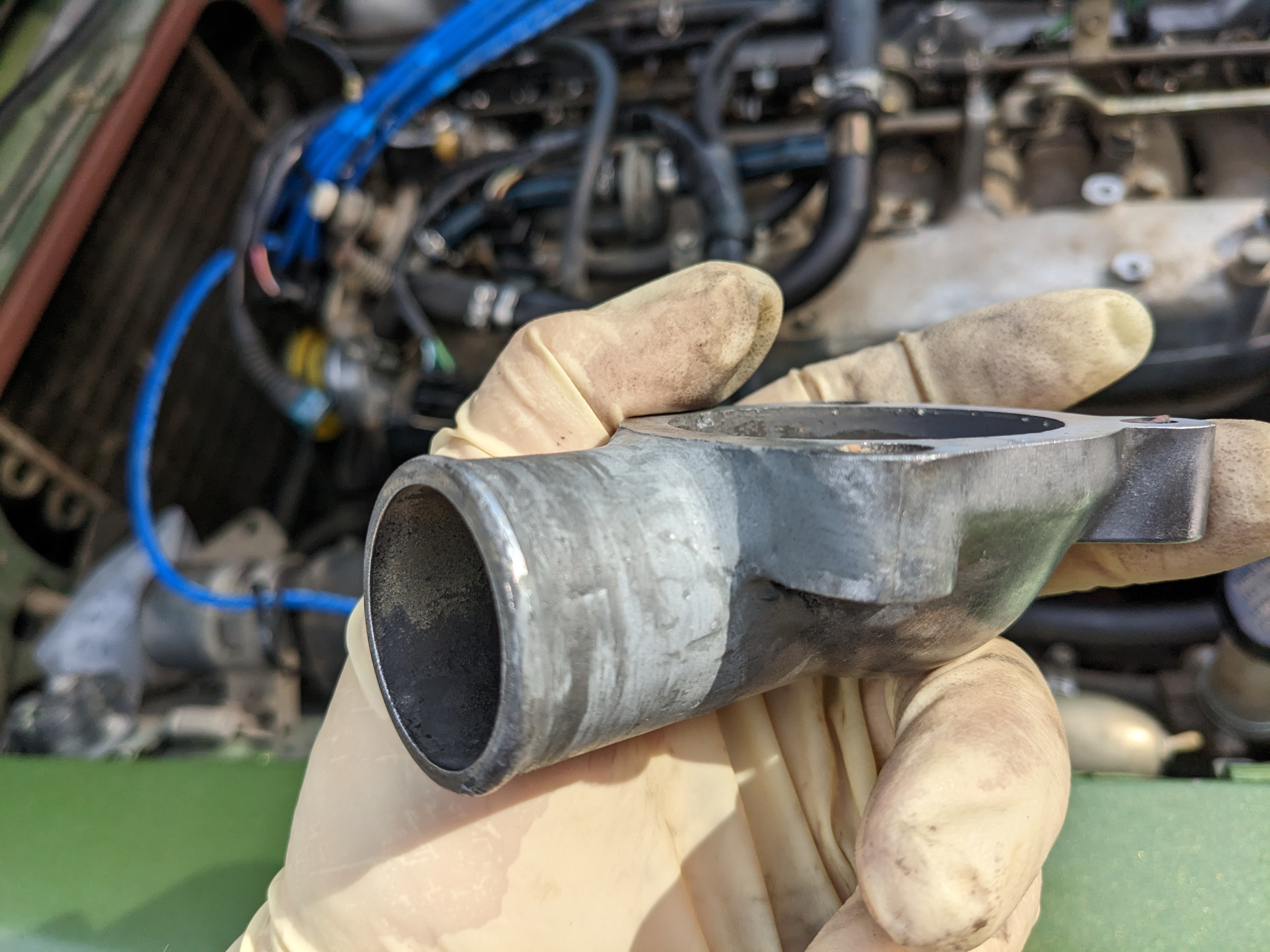
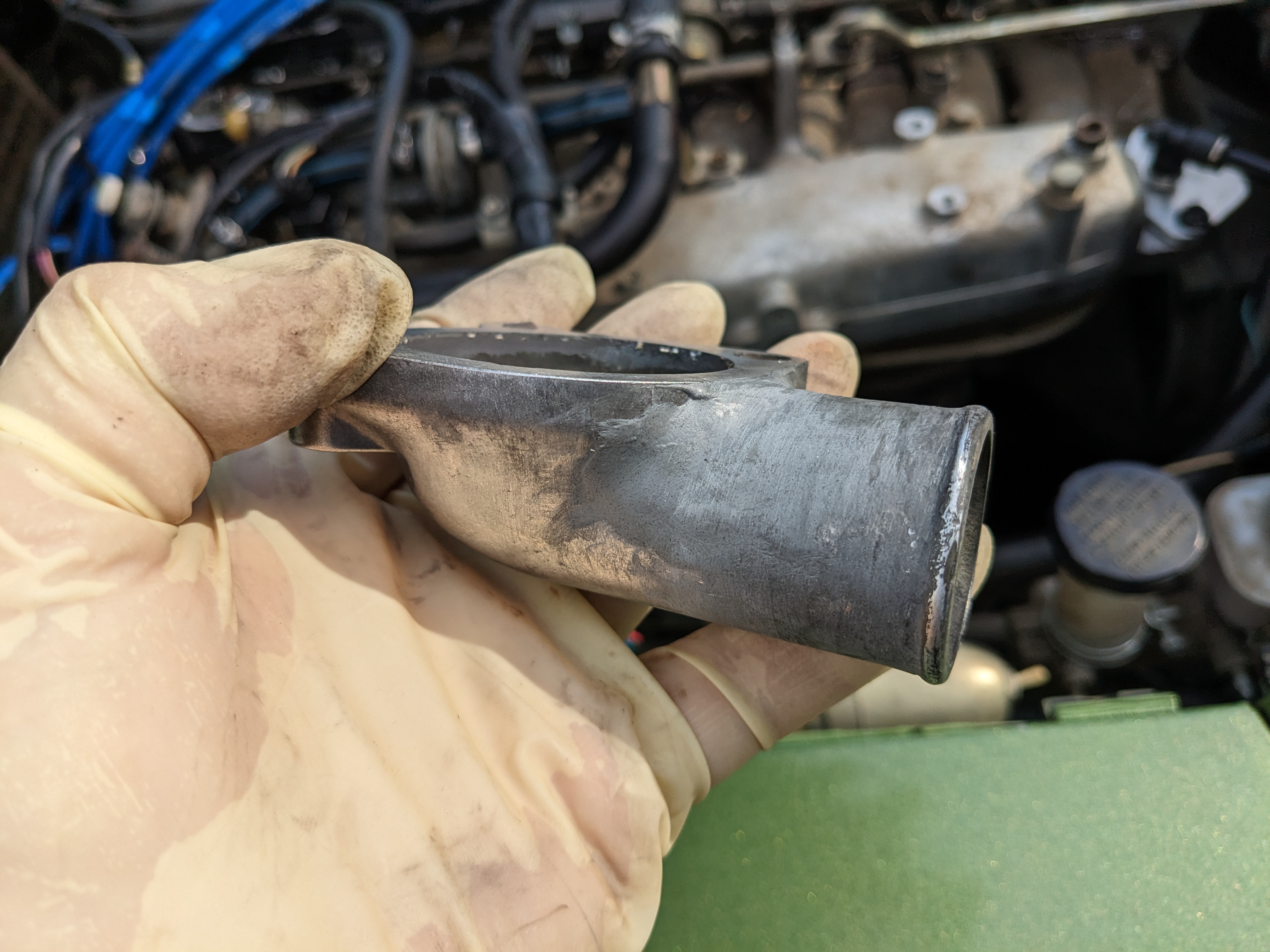
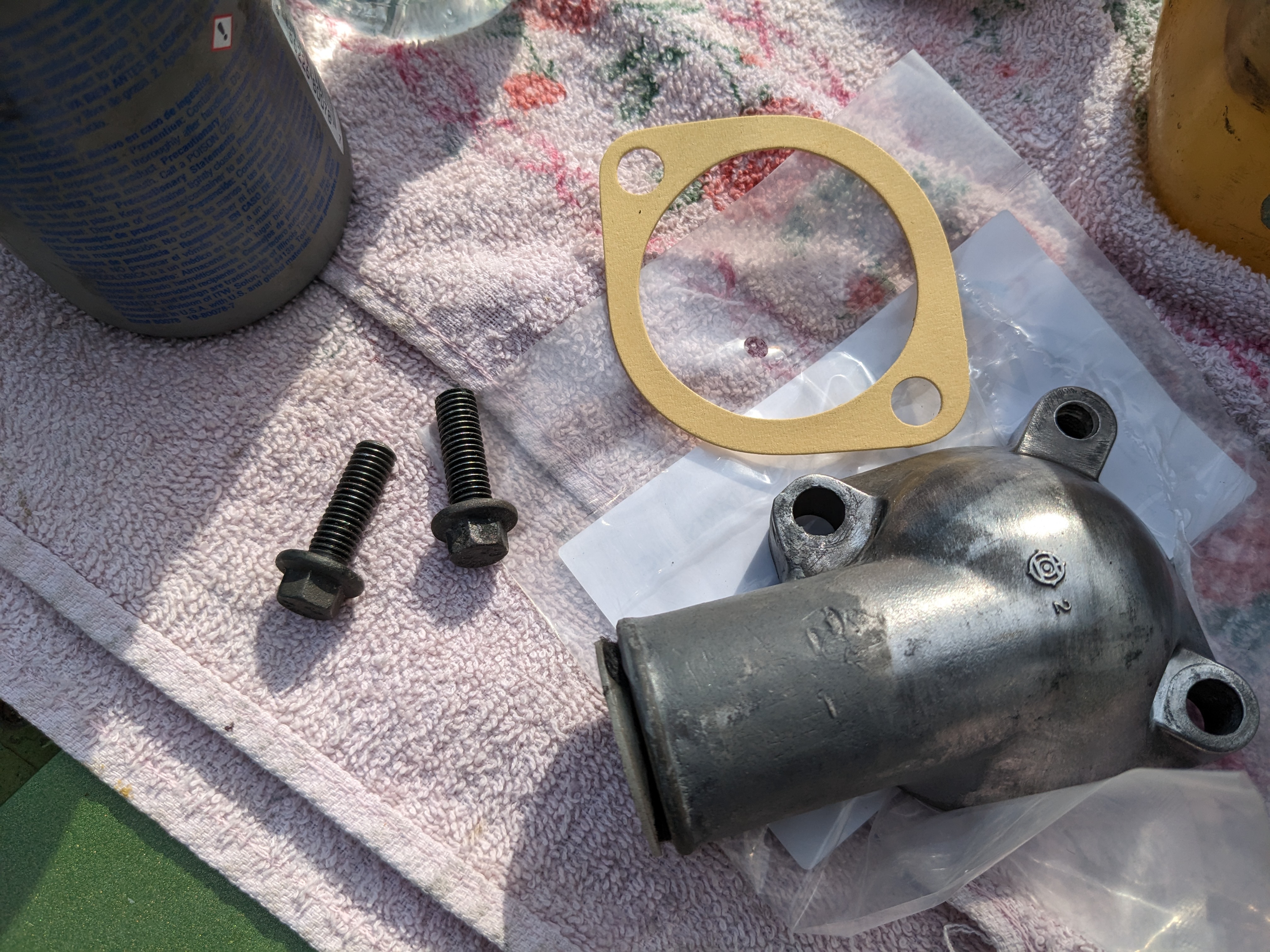
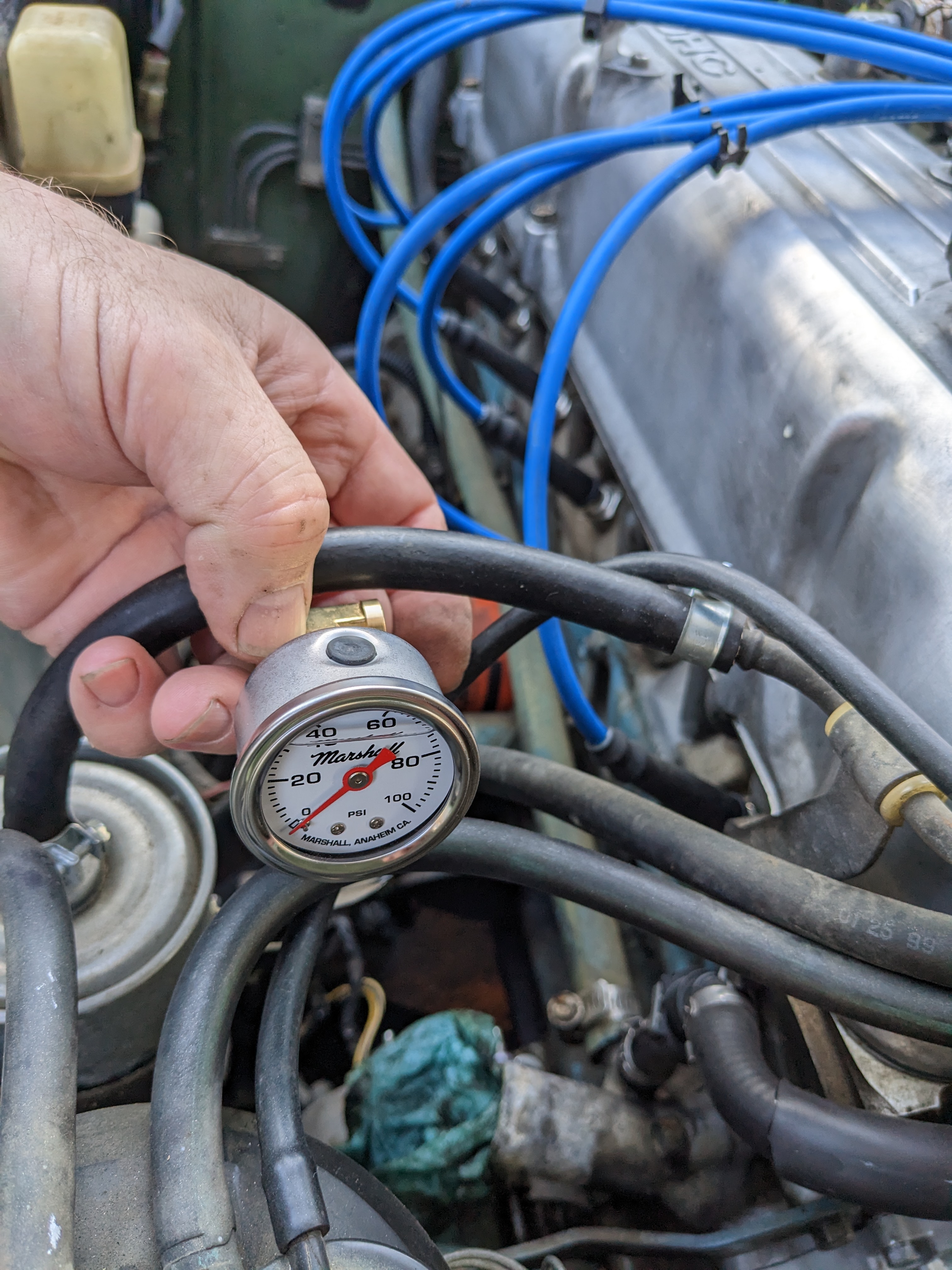
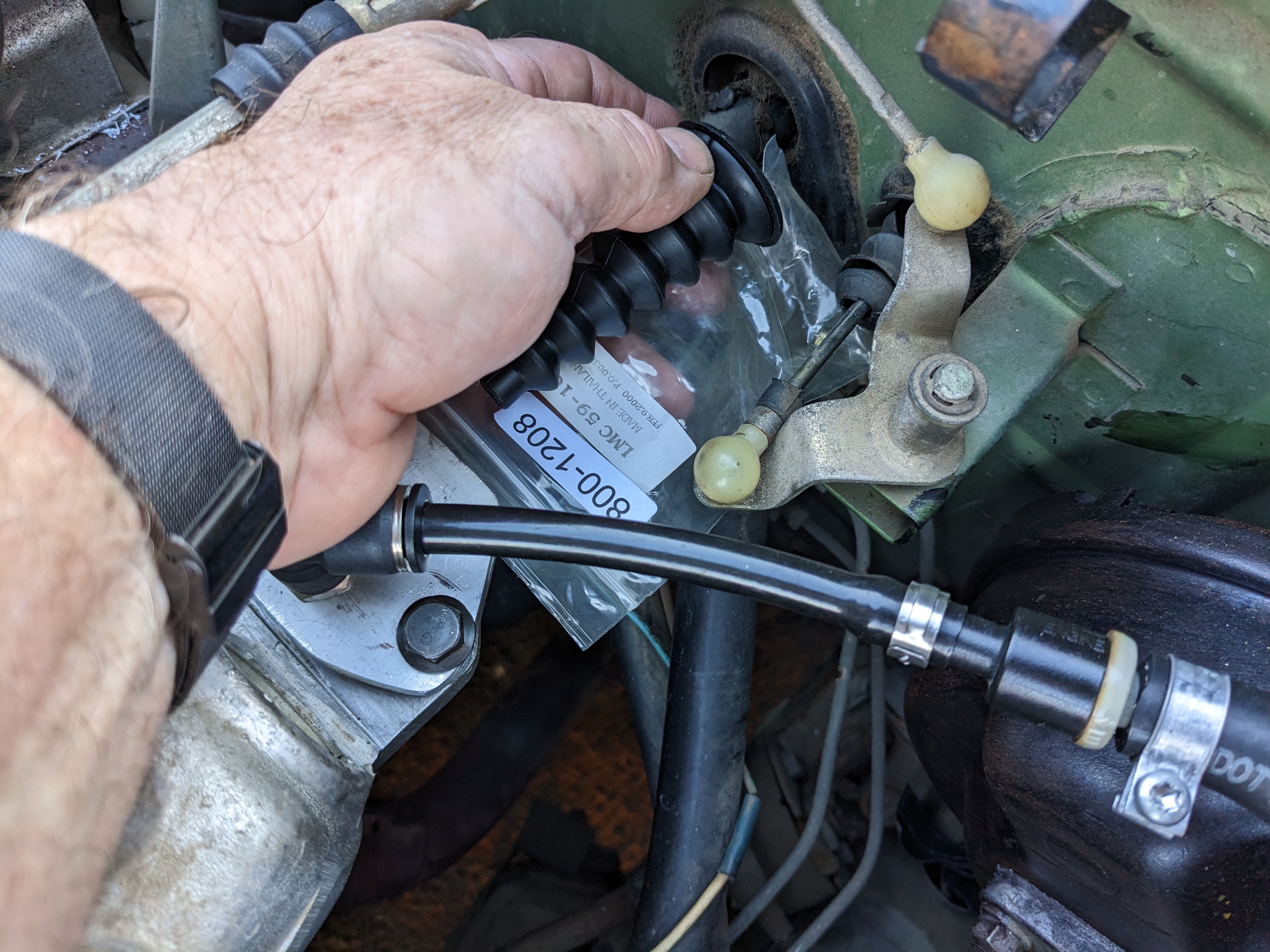
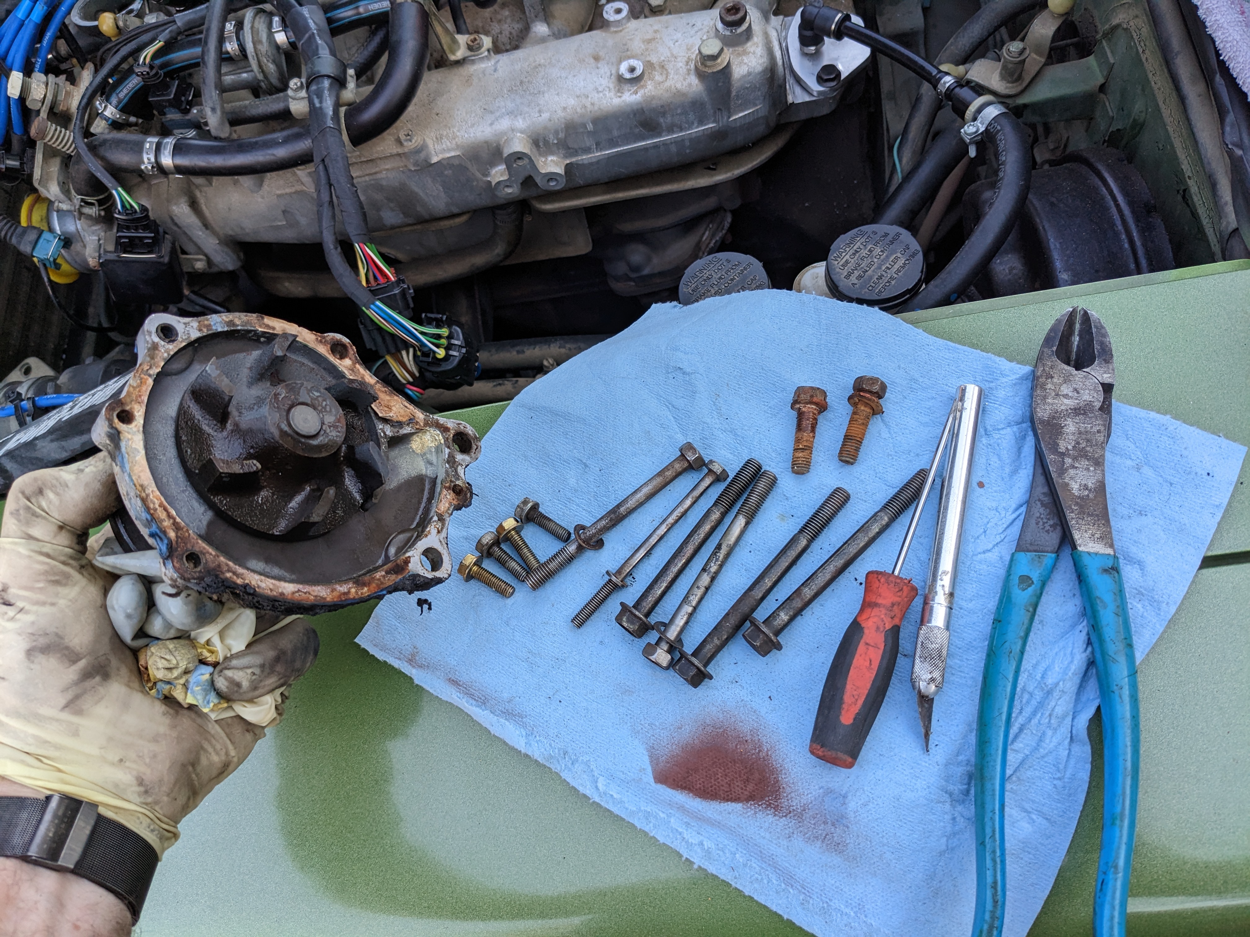
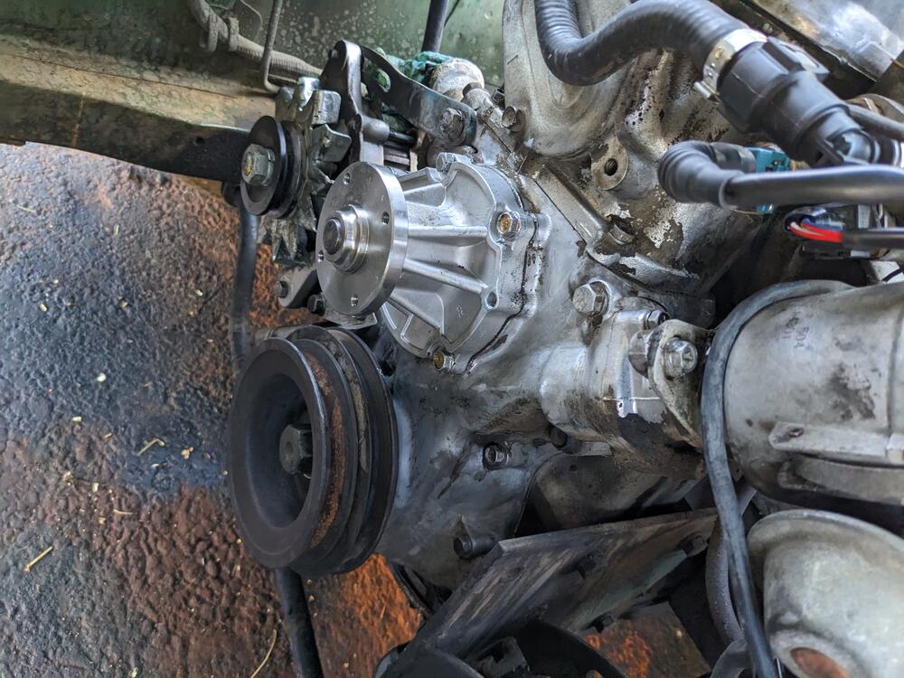
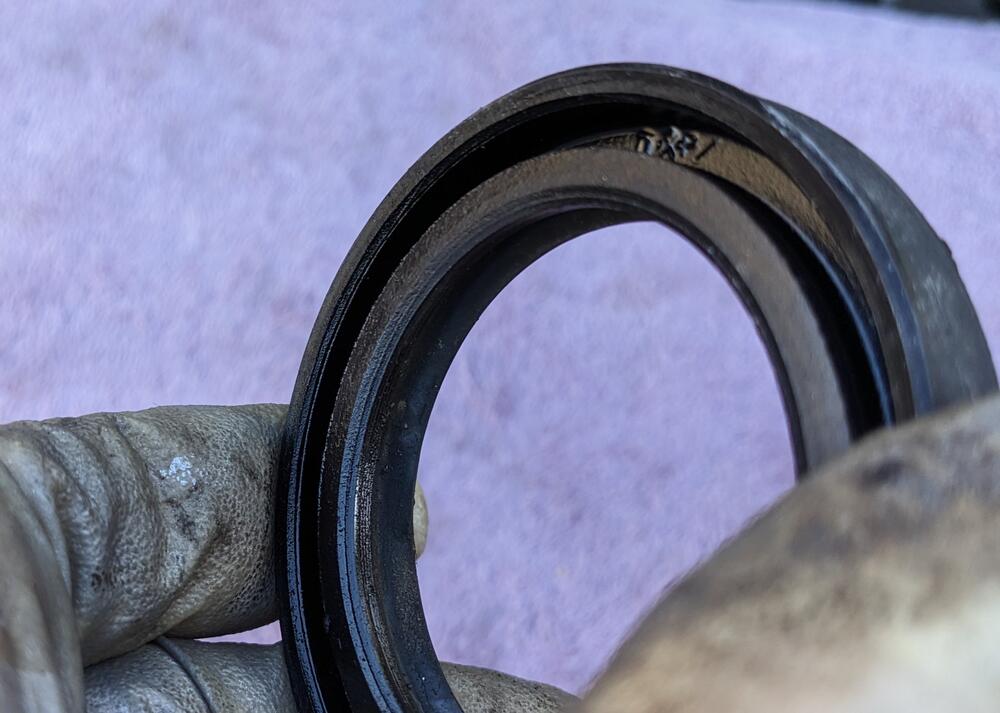
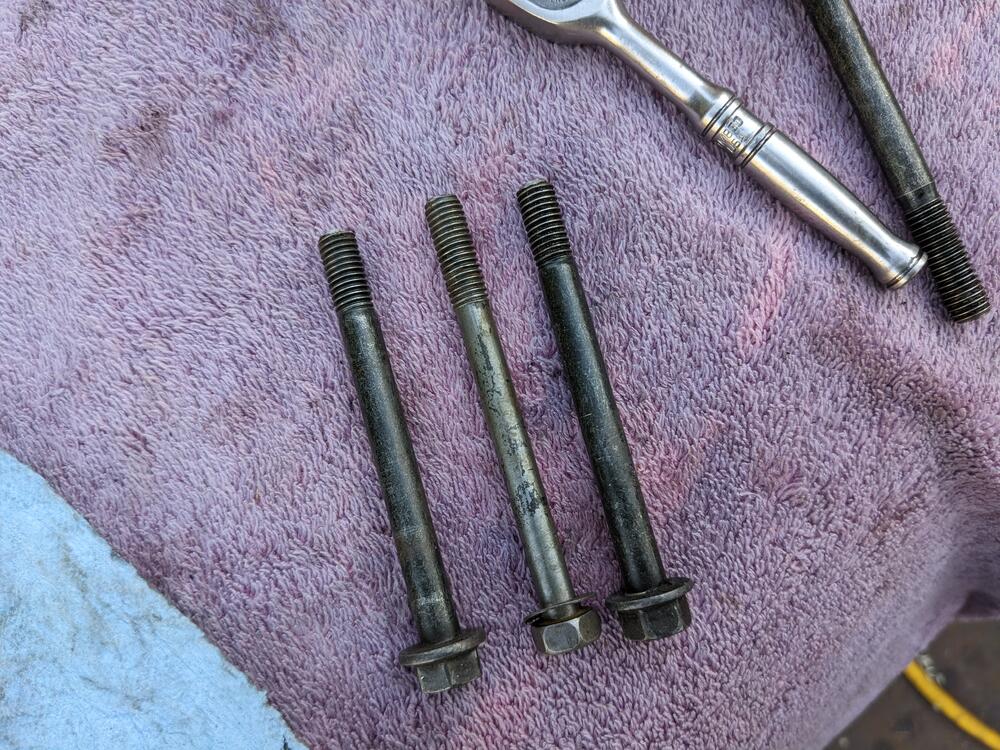
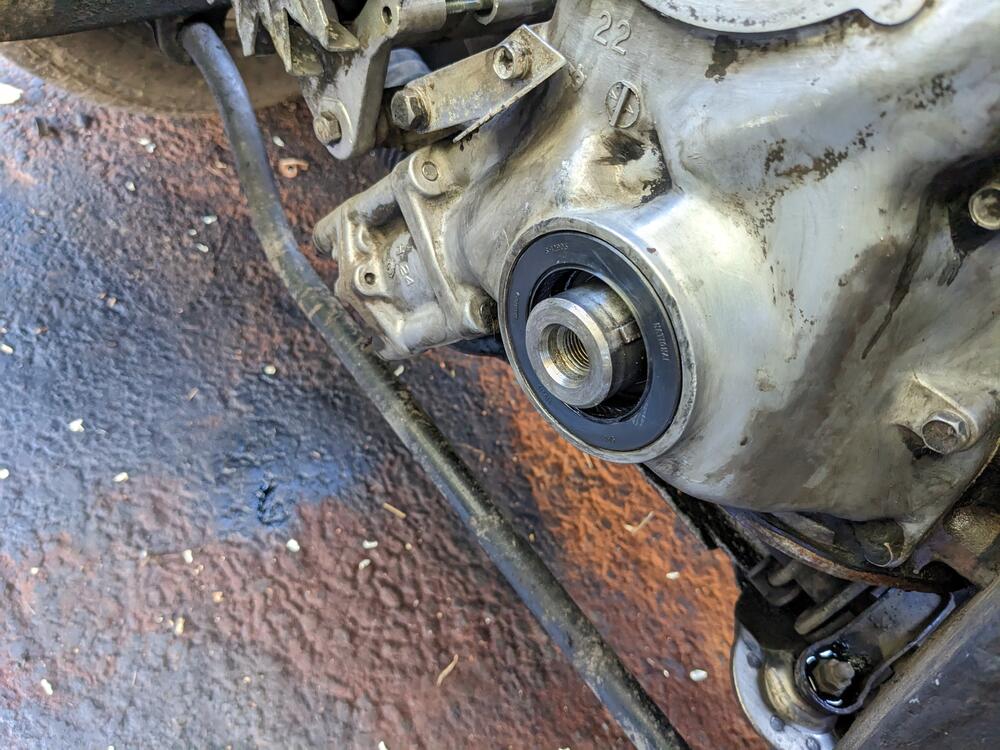
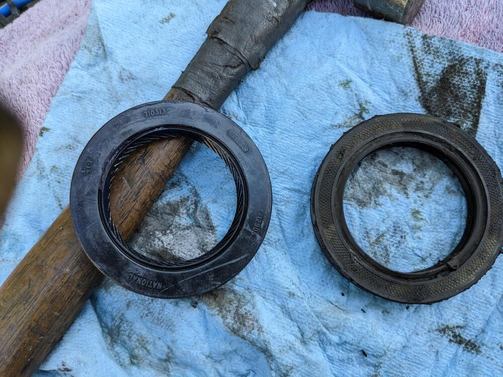
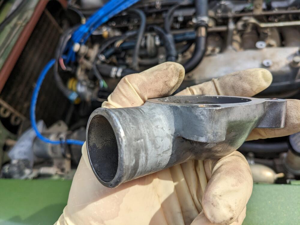
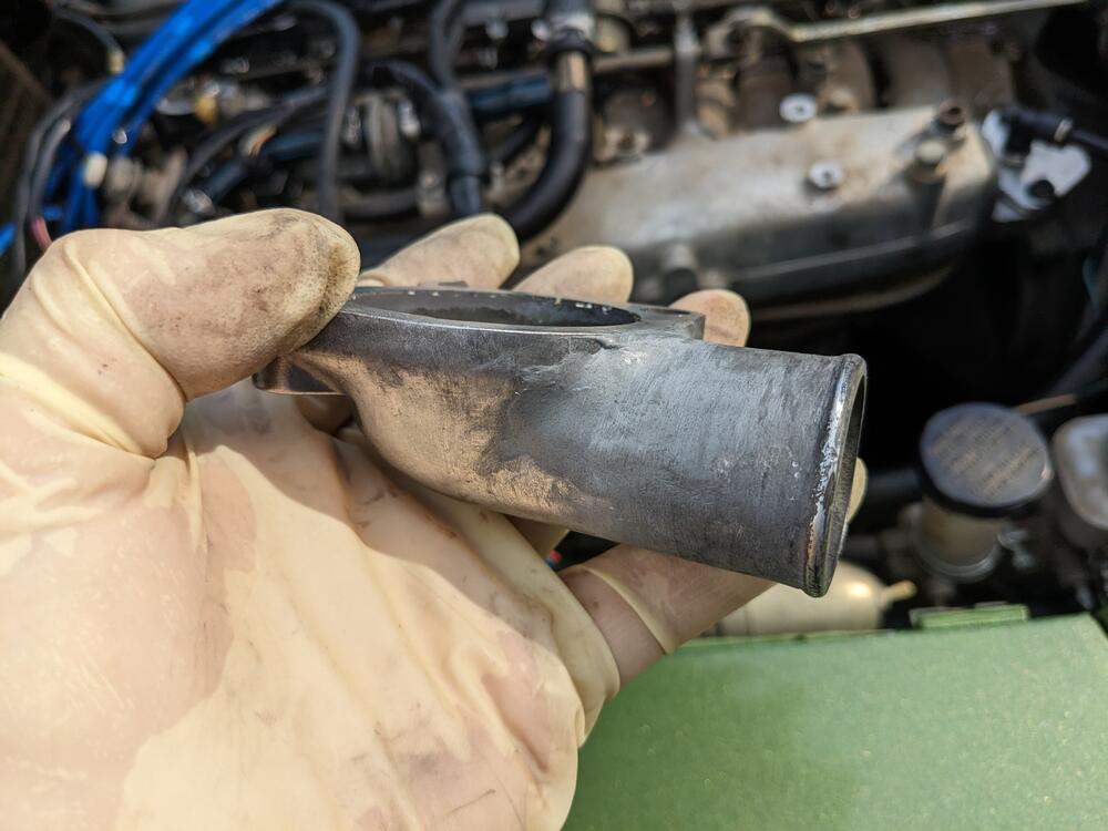
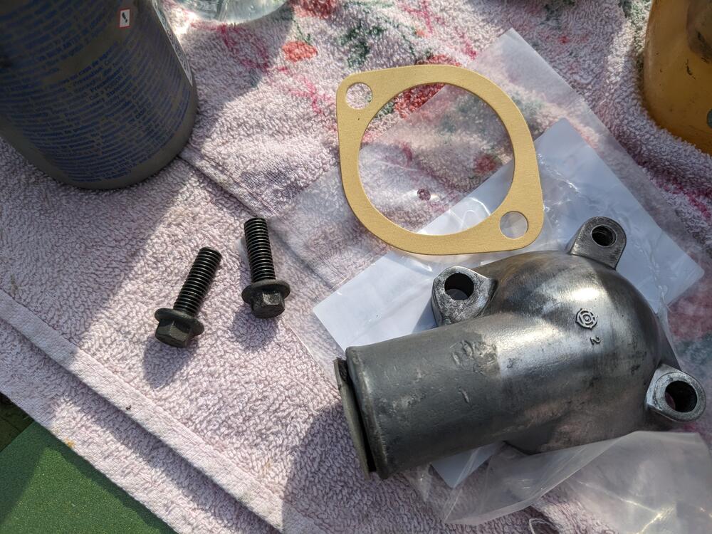
Cleaned up around the crank, and removed the pulley & old seal. Definitely well hardened. There is a decent wear groove on the pulley seal neck, so I made sure to alter the seal depth for the new one After that I cut down the Volvo bolts to match the Nissan length (checked that at the full length they would bottom out before pulling the pump tight to the casing) New pump back on Repaired T/stat cover Volvo bolts, cut down to match Nissan original length, with 10mm heads to make it easier to access by the fuel lines, and harder to overtighten In other news, going to add a fuel pressure gauge over here And got a new throttle cable accordian boot. Not planning on driving it in the rain, but I don't want NY weather working it's way into the cabin
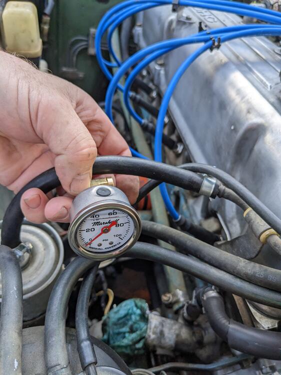
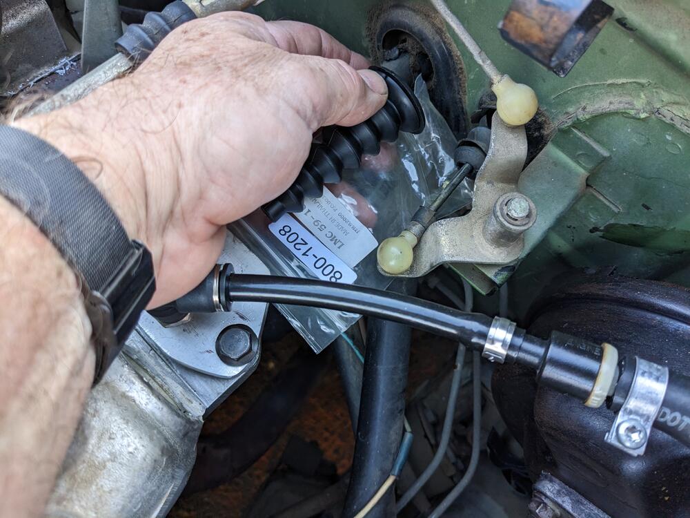
-
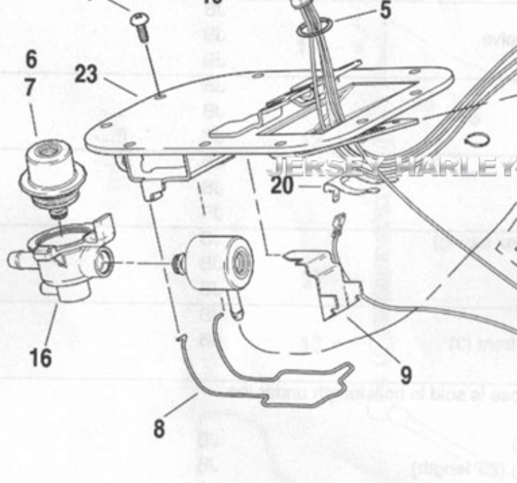
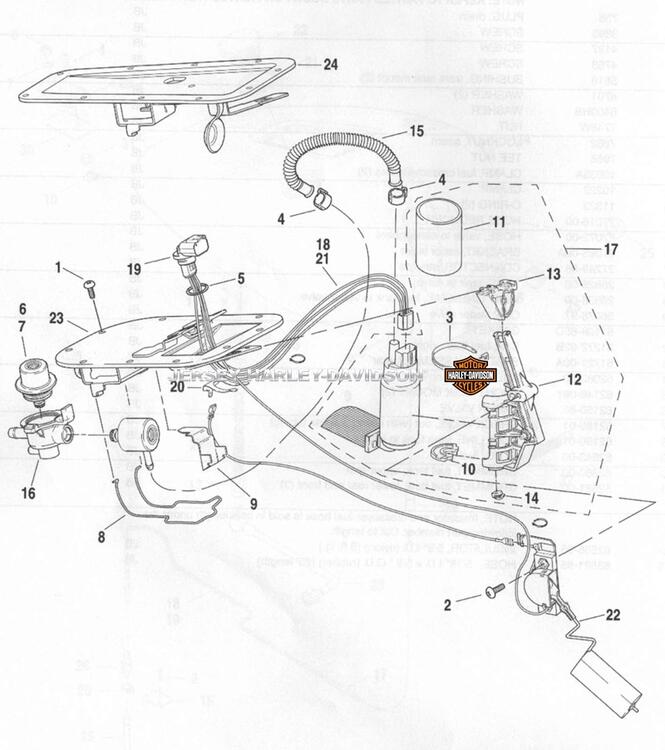
Trying to find a schematic - typically the bottom-most port is the return - the I/O are in line with each other in the larger housing, so that female side may take some sort of push fit line, I dunno. EDIT - yeah the female is the inlet, looks like the have a designed filter pressed into that
-
We need 2.5bar for the Z? The adjustable one doesn't drop below 3bar either.
-
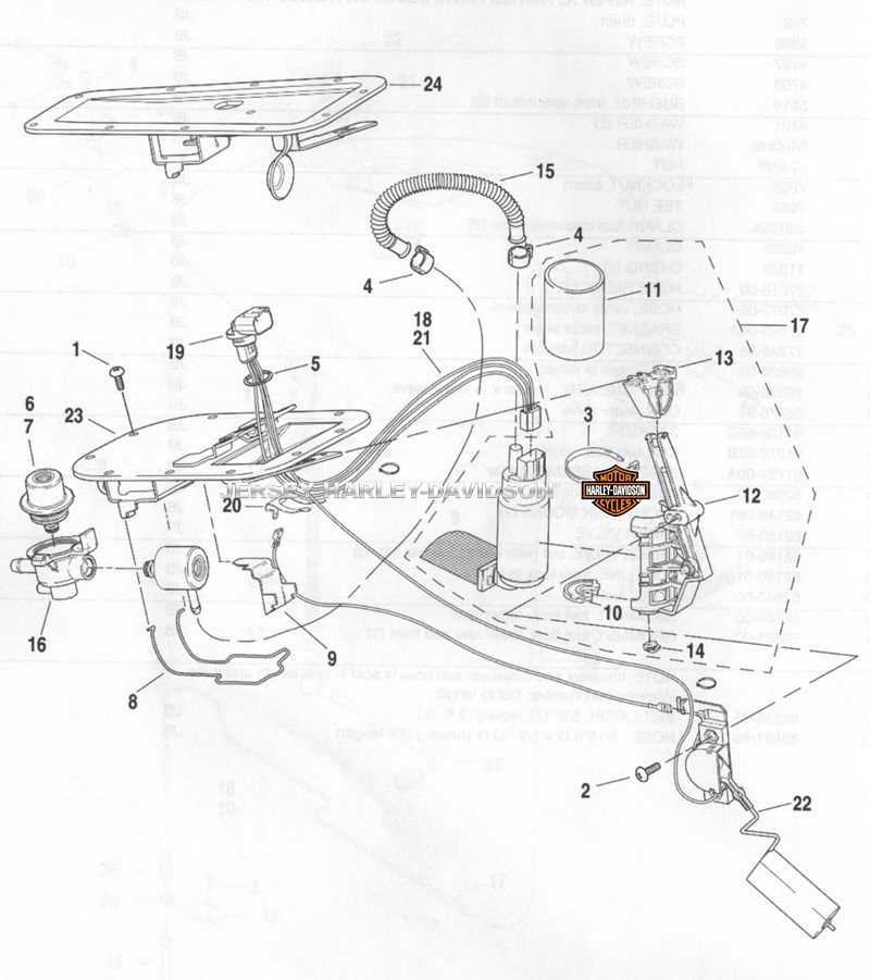
The adjustable regulator is this one: EuroSpec Sport. The standard (non-adjustable 3bar) FPR in the 2nd pic is what all Volvos & VAG came with. The black plastic pod that it sits in is a separate part that was only sold with the feed & return lines attached, so pretty much the only way to get it is to cut it from a parts car. The Volvo 3bar FPR is PN 9404583 for reference. They don't go bad, so if you were going to use one, I'd get it used. EDIT - VAG # 037133035C Bosch # 0 280 160 557 EDIT - this is an aftermarket housing that accepts that style FPR. I just found that searching, so there may be other (less expensive options) This composite one for a Harley also accepts the same design FPR, don't know if the ports are useable
-
Both of those types are common on Volvo 240 / 740 / 940 series, depending on year. There is a 2.5bar version of the first style (o-ring). The o-ring fitting is the same dimensions as any composite injector, so a universal injector bung could be modded for use. The last one you posted was used on all Fiat/Bertone X1/9's with EFI - 1980-87. There are FPR pods used on 90's Volvo (850, x70) & VAG models that has a removable FPR. Those you can buy Adjustable FPR's for, which would allow changes depending on tuning & other mods. I used one on my old Volvo converted to pickup truck when I +T'd it Downside is you can't buy the pod - it comes with nitrile/nylon sheathed lines attached. I cut them off and/or cut them down & make my own lines Gm also used this design FPR on LS motors - I know because the one I'm putting in my pickup truck has a housing that has the Bosch FPR. So there may be other options. I think using the 3 way Volvo style would work the best in terms of compatibility with the rail, since it has input, return & regulated output . I have another I scavenged from a parts car many years ago, so at some point I can test in on my '75 rail...
-
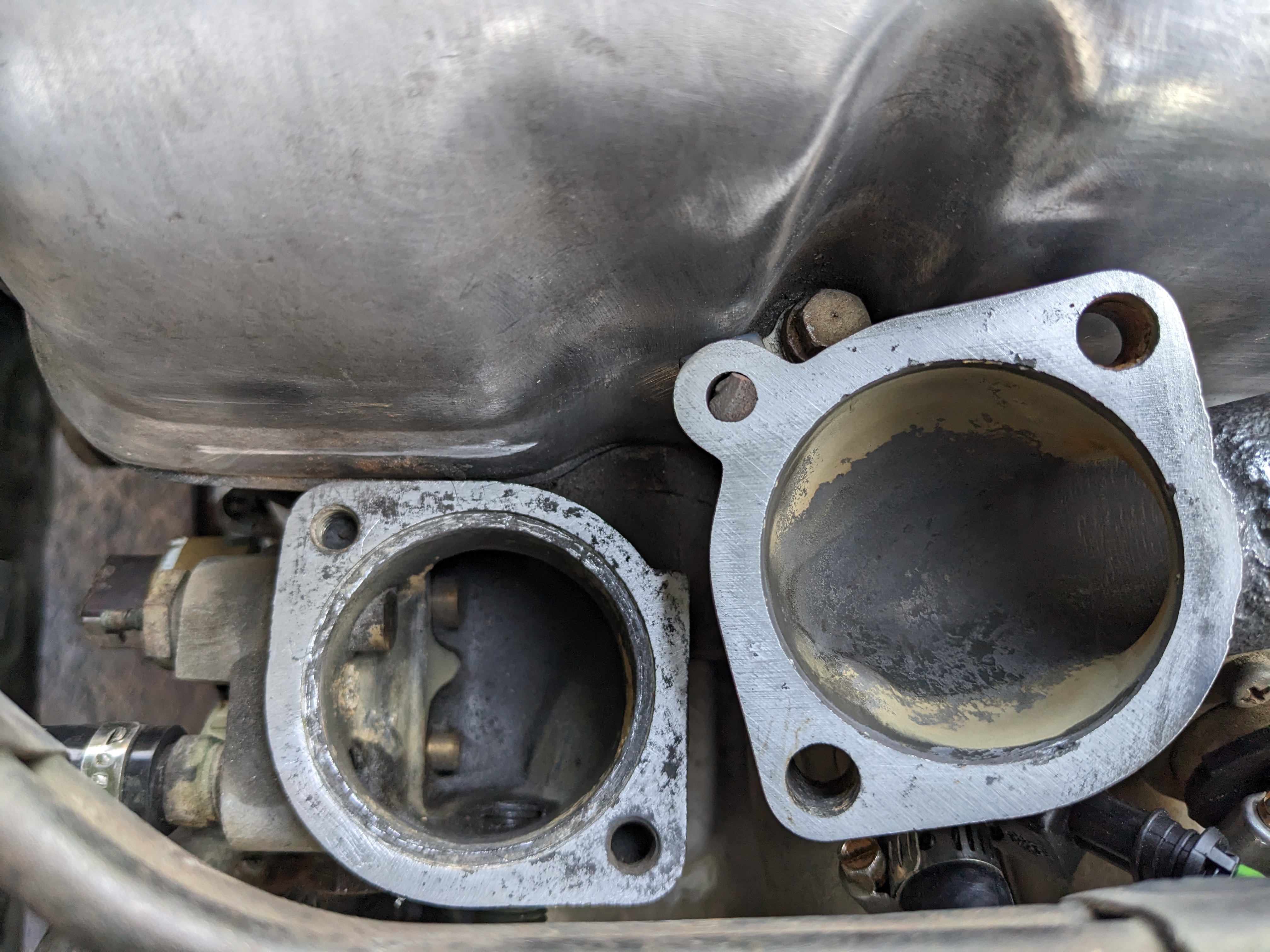
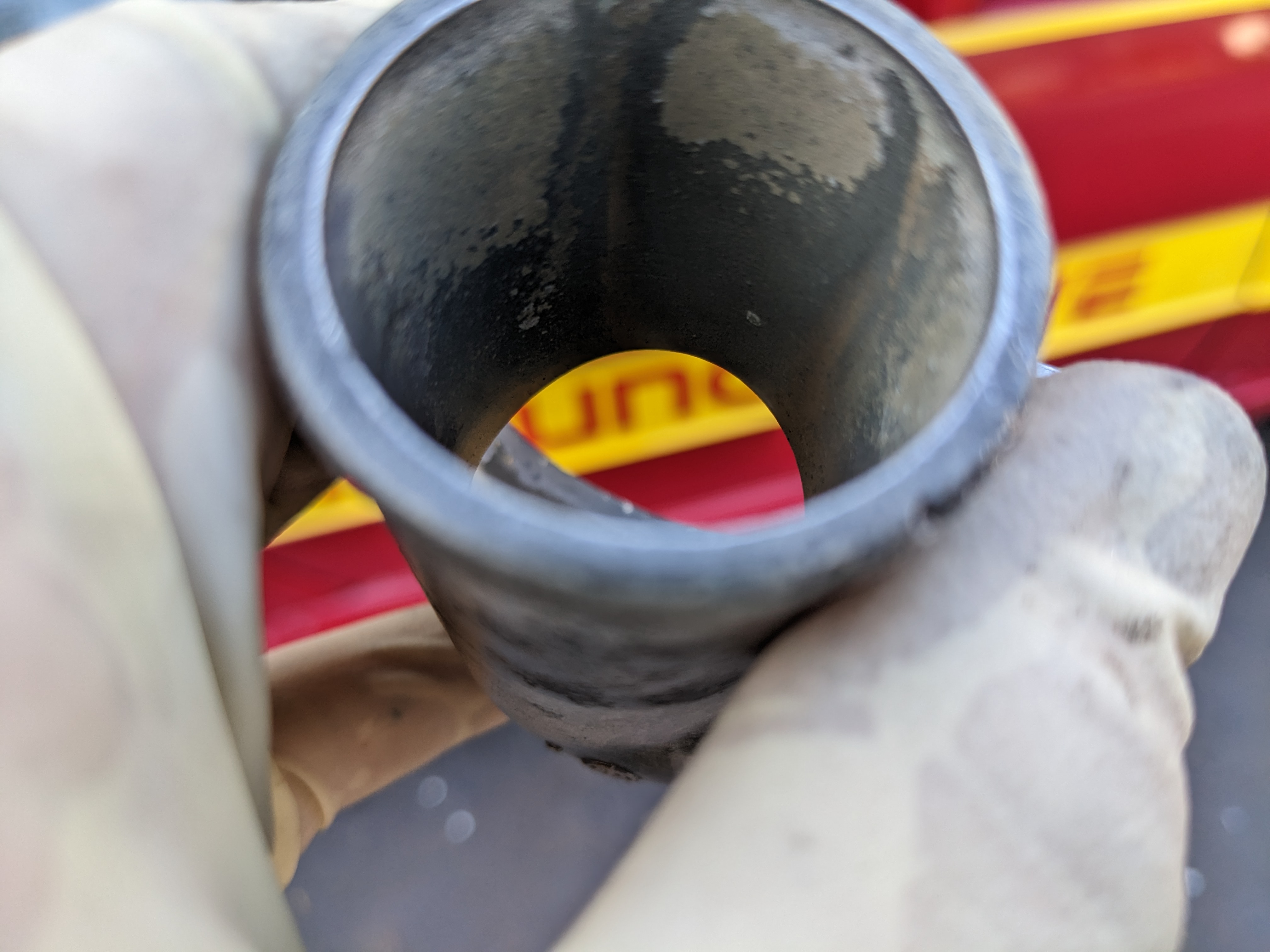
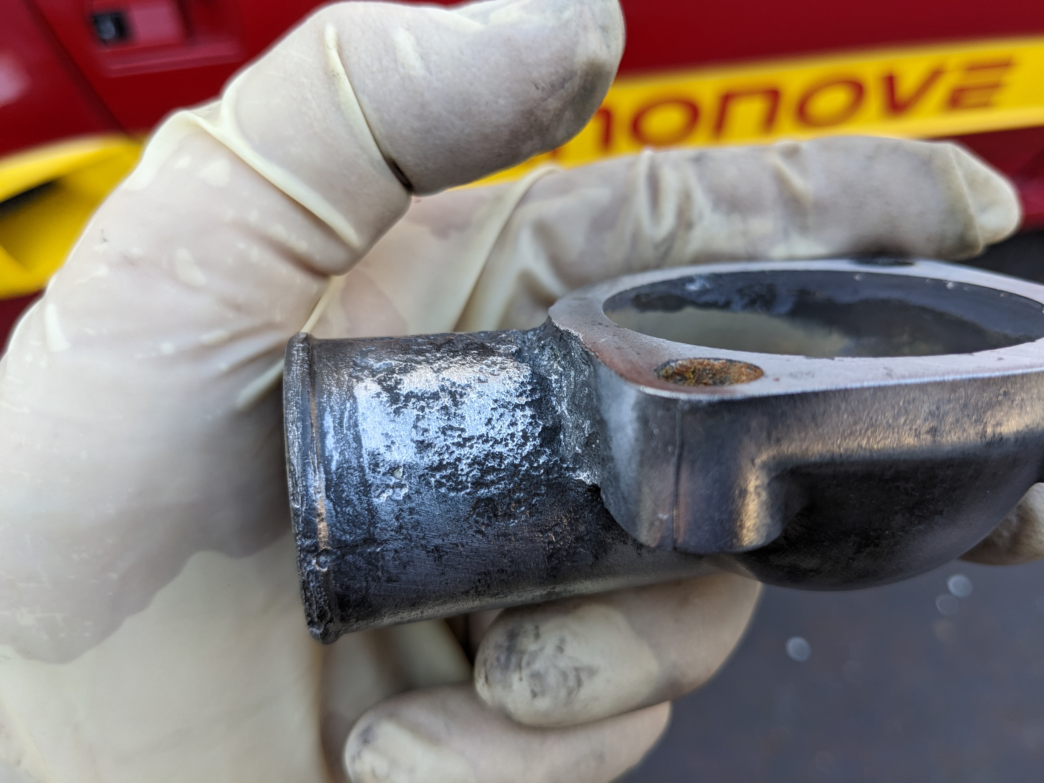
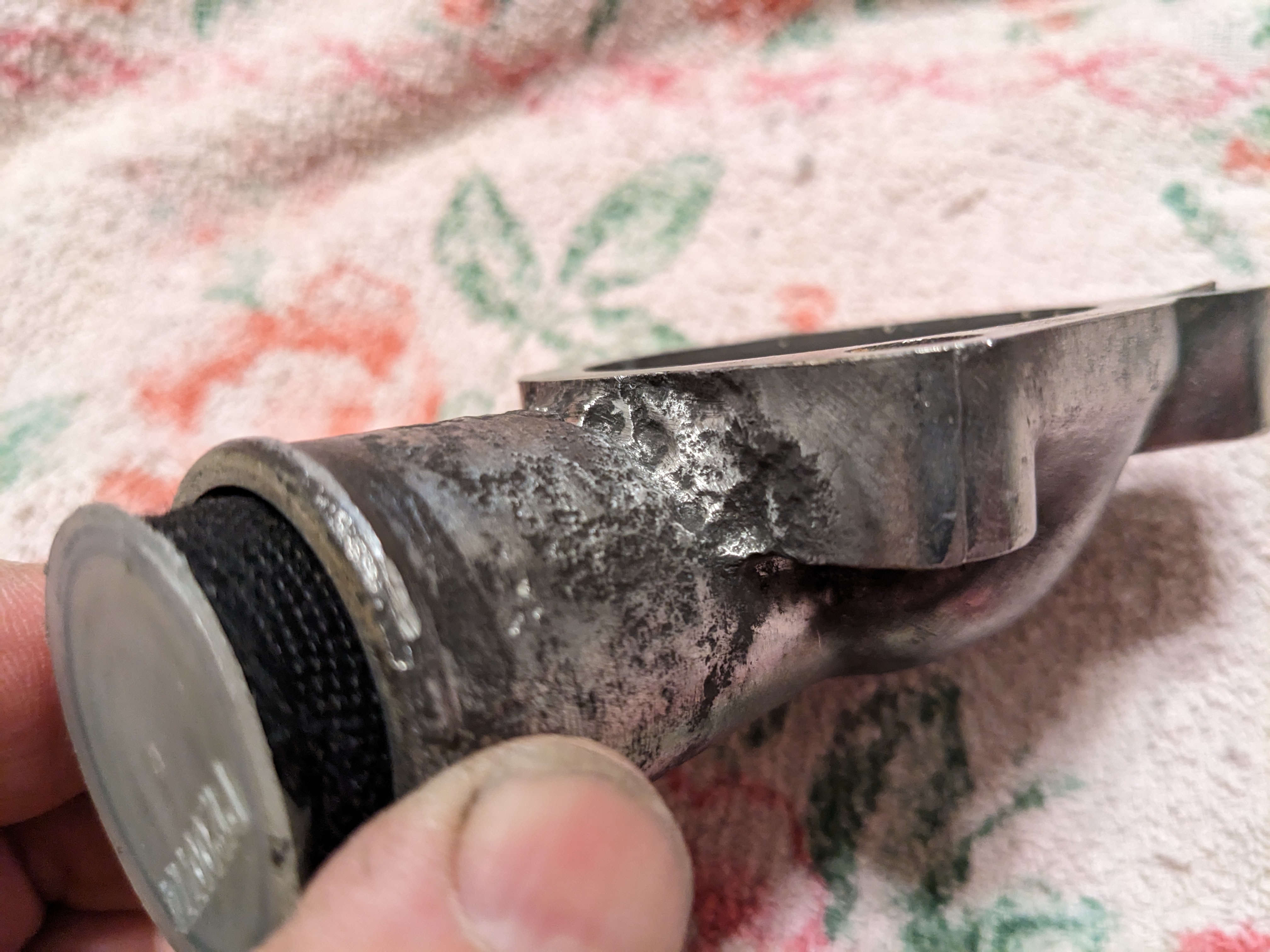
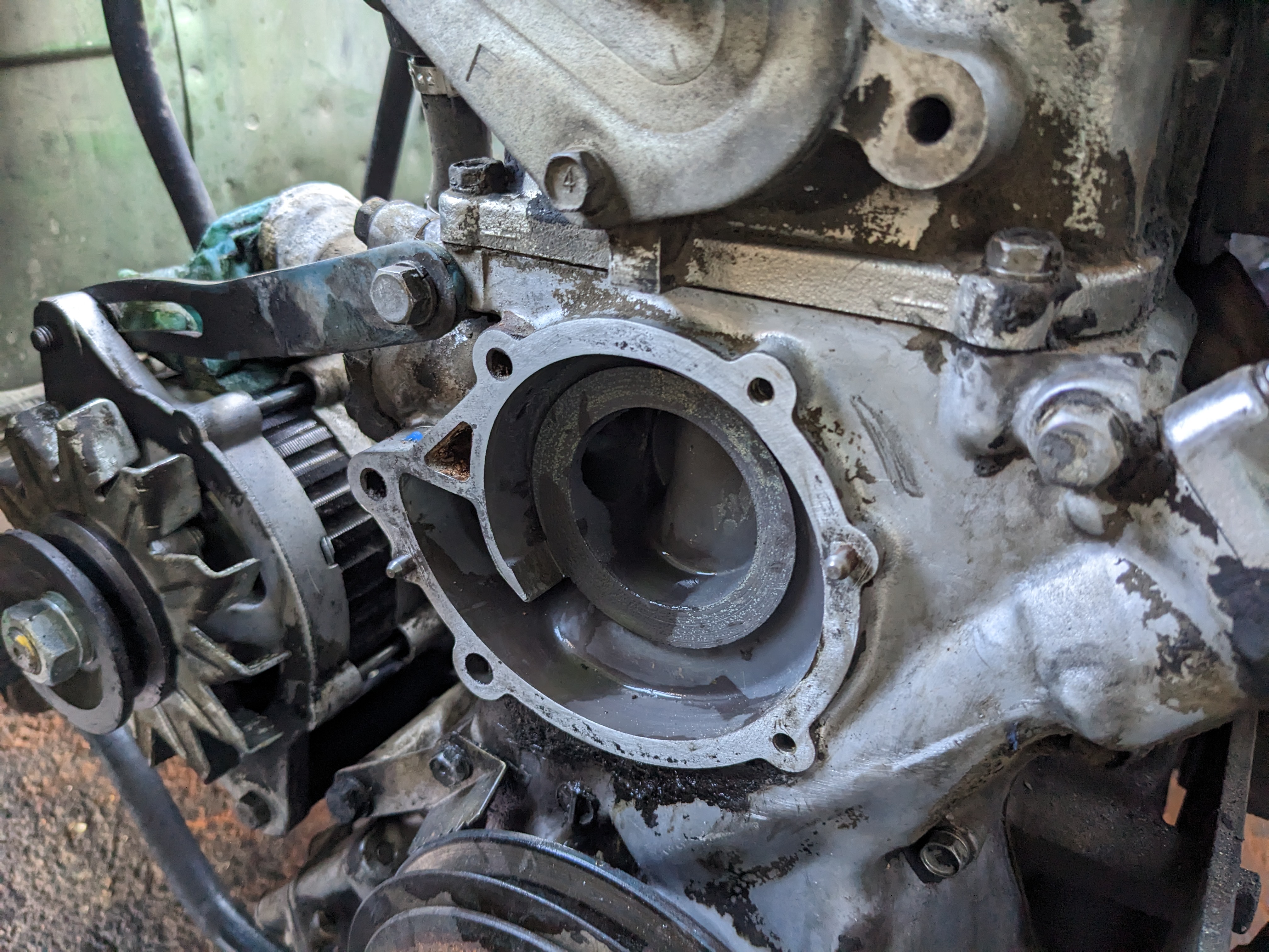
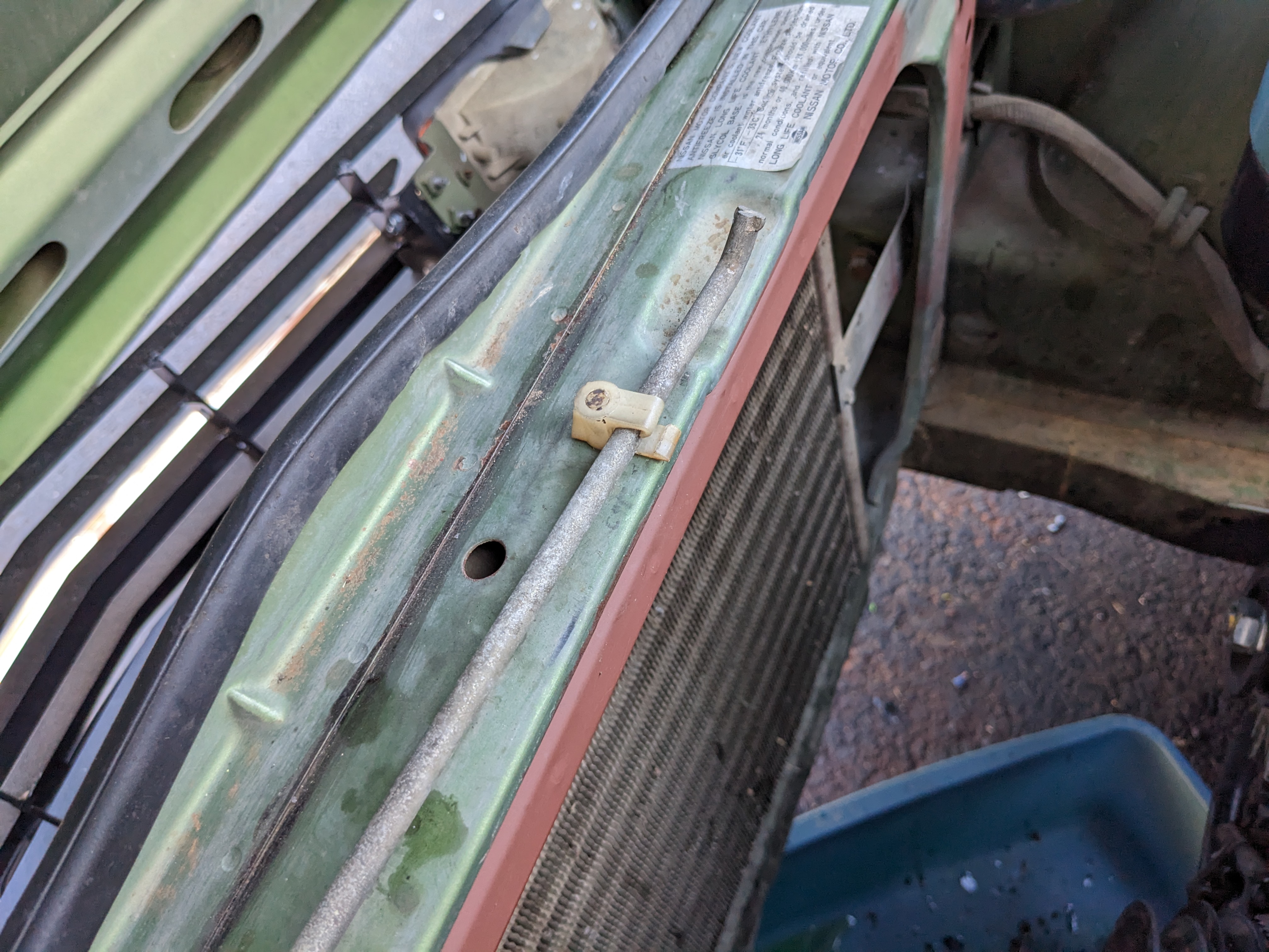
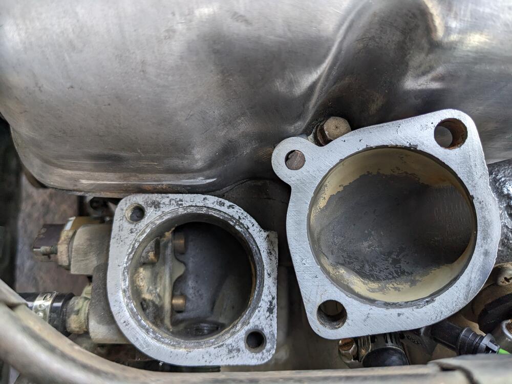
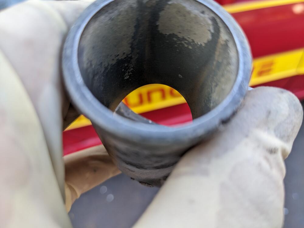
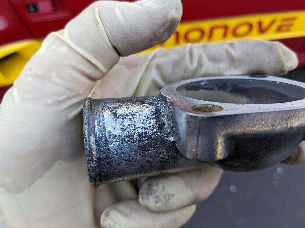
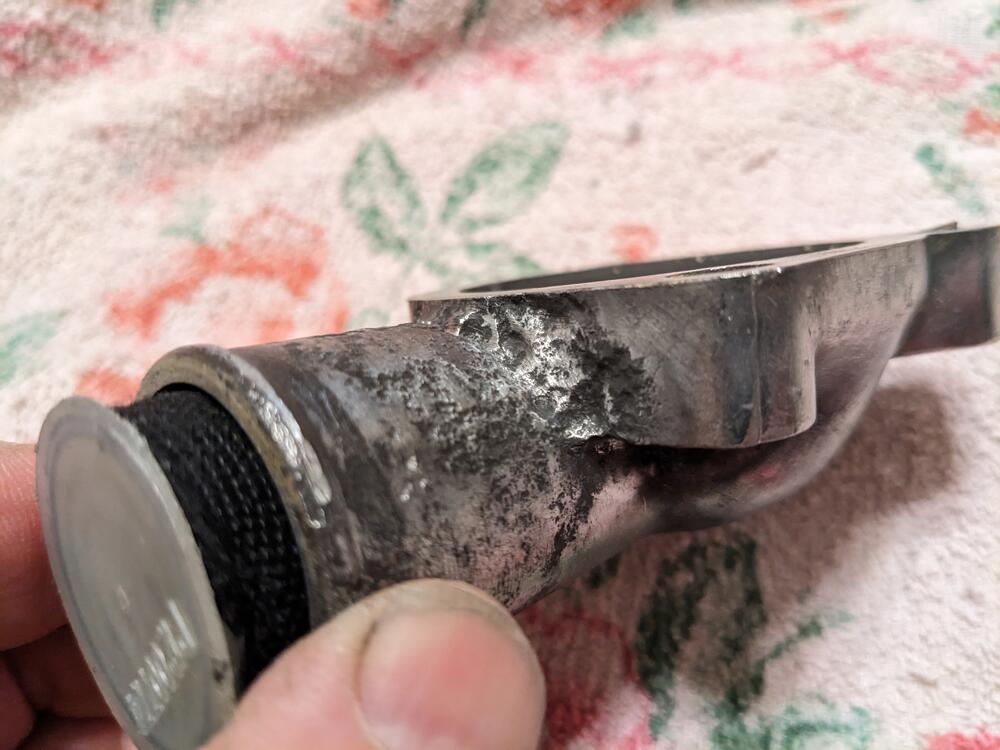
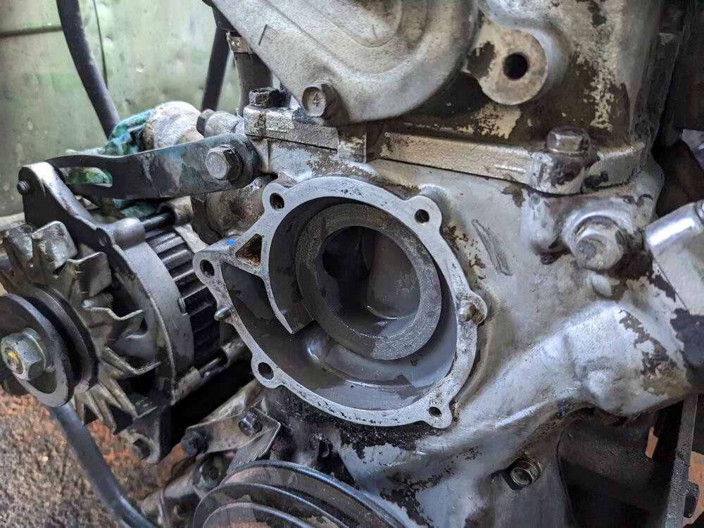
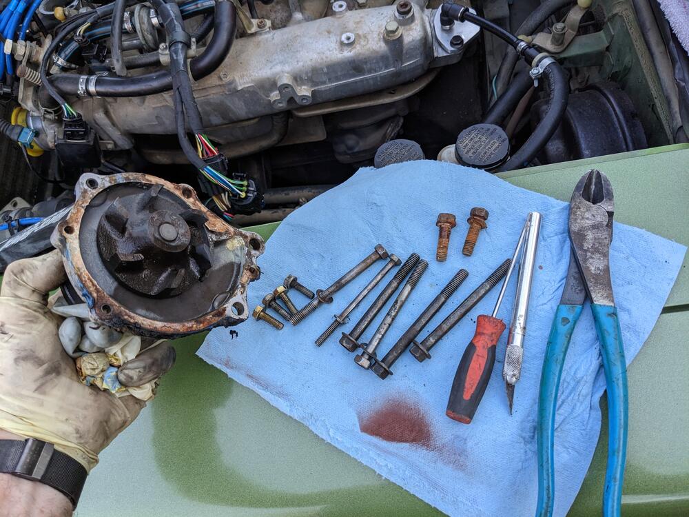
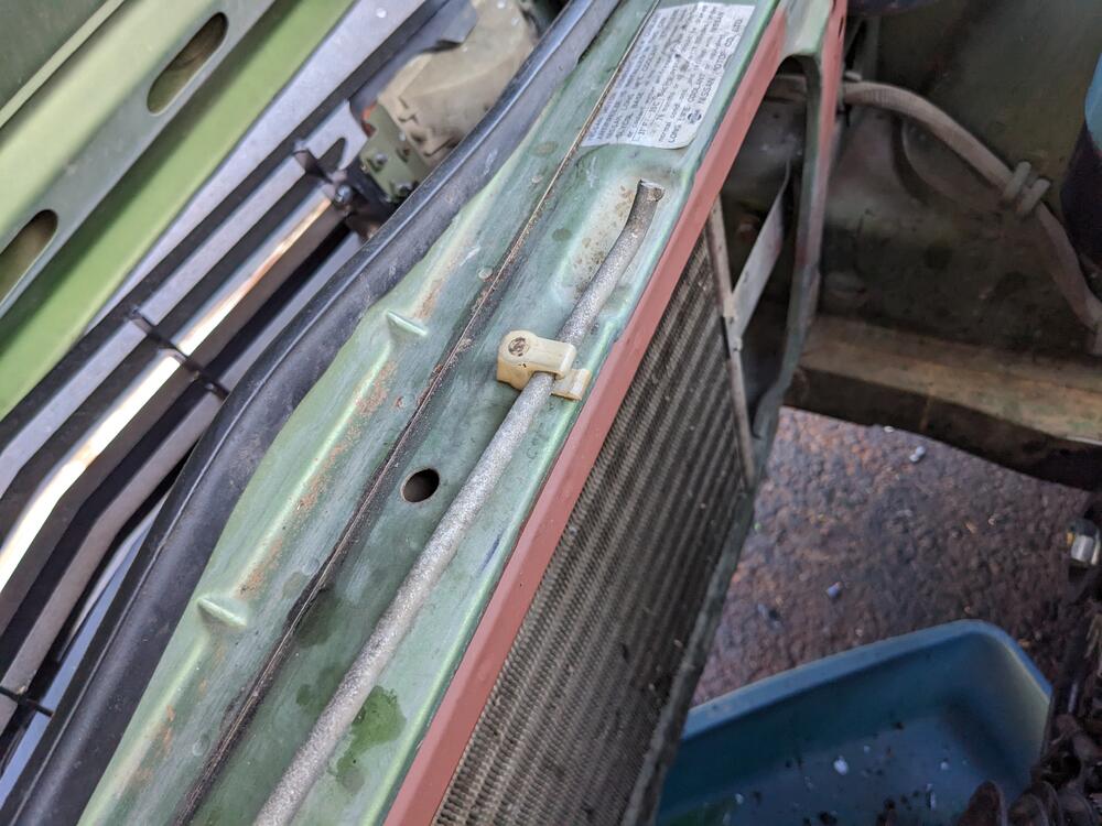
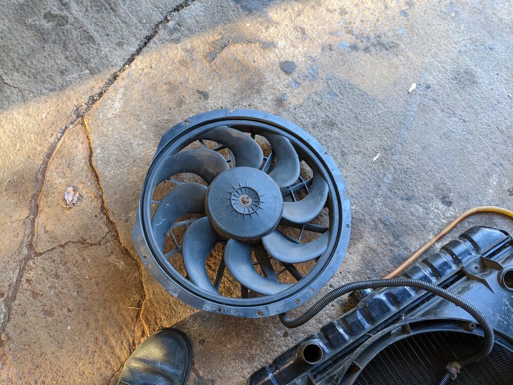
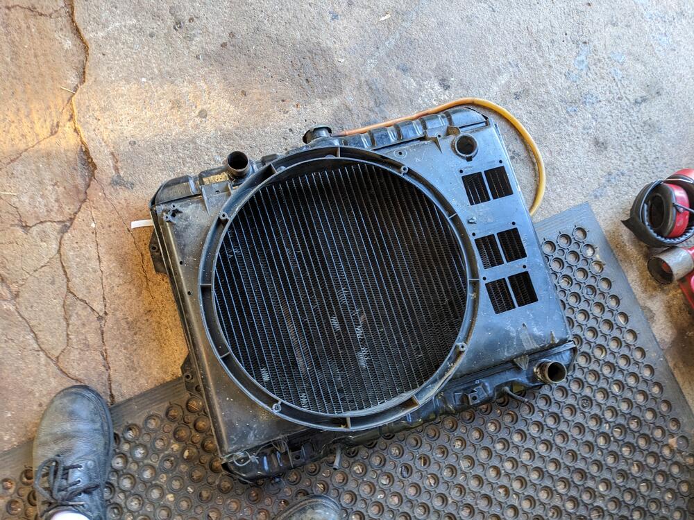
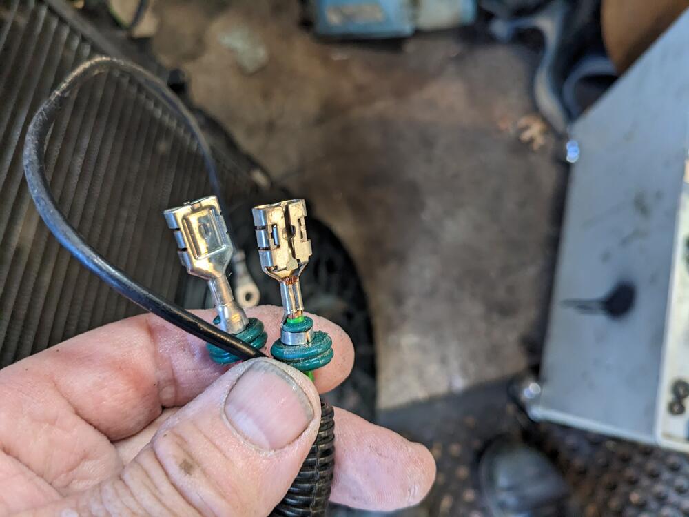
T/stat cover came off without too much drama. I had to block sand both surfaces, they were both pitted Chased the threads in the housing, to clean it up. There is pitting in the underside of the cover neck, but the inside is clean. I can only presume coolant has been seeping past the (crappy) Gates upper hose, that wasn't quite the right ID. Cleaned up the pitted area with a Dremel wire wheel, I'll fill it with JB Weld Water pump bolts didn't feel great coming out, so I worked them back & forth fair bit. Mating surface mostly cleaned up here The original hardware for the water pump cleaned up OK, but I think I'll use newer hardware. The T/stat bolts are nasty. The Volvo bolts have integrated flanges & are higher grade While I was in the bay, I added an 80's Fiat brake line clip to replace the broken hood prop retainer (and put some primer on the area where the rad sits up against the panel Checked the fit of the Volvo fan shroud on the rad - should work OK, the center of the fan motor will be offset to the left, and the water pump sits offset somewhat to the right. I'll test fit it once I figure out a suitable method of retaining the shroud flush to the rad core motor.. Have to locate mating pins and/or water proof housing for the eFan connections - pretty sure they are Furukawa or Yazaki ? EDIT - Yakazi 58 Y series EDIT - assuming the shroud & fan clear the waterpump snout, I will wire the fan same way I did on my old Volvo
-
Is that Good luck (not likely to work out) or Good Luck (I hope you are successful in the attempt) 🤪
-
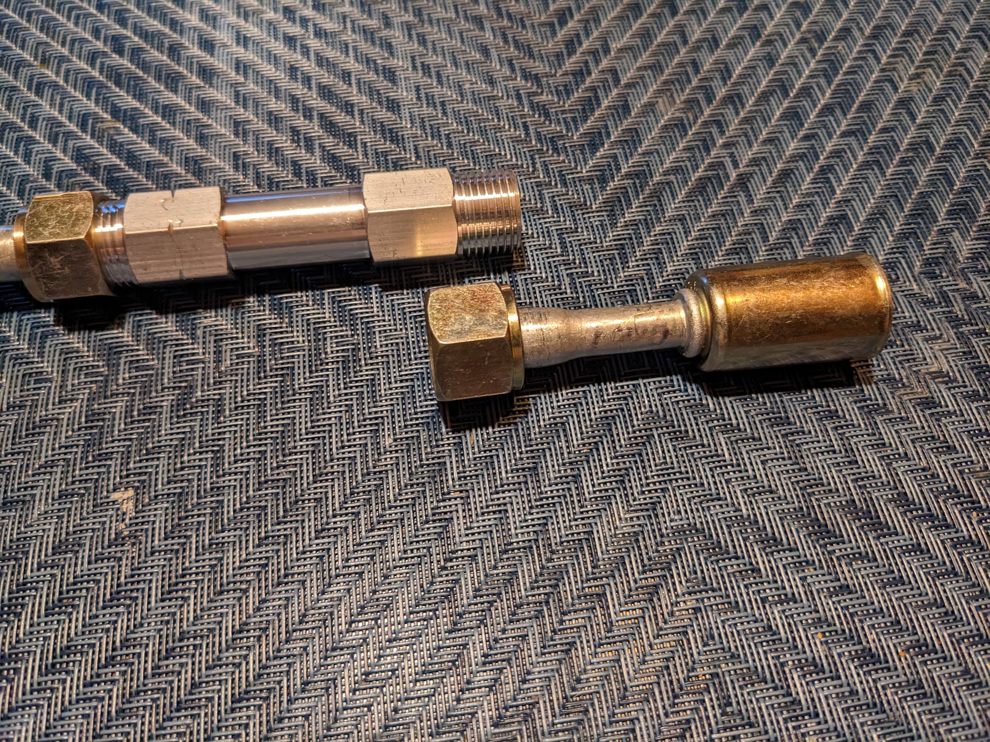
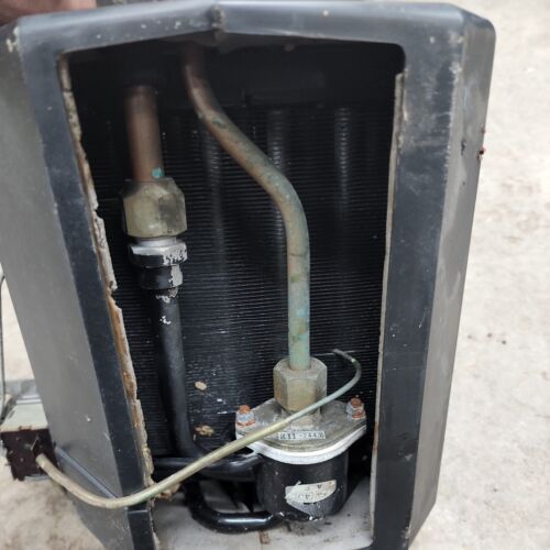
Hi Steve Thank you for the offer. I think what I would need to explore this are the OD and thread pitch of the Male fitting and the ID of the Female fitting, where the lines exit the firewall, and the two male fittings on the Evaporator itself - if that's what you have handy. I took this image from the eBay listing. I need to establish if they are all metric or standard. Judging from the other pics, the line fittings are flared (JIC perhaps?), which is not standard for any US type o-ring style fitting (MIOR, MOR, FIOR, FOR, etc.,) This may not be worth the effort if I have to make lines that go into the casing to attach. I don't see any way to convert the outer fittings to o-ring style, unless someone sells repair ends that can be silver soldered to the existing hardlines. There are standard (#6, #8, #10) male & female flare beadlock fittings, but they will definitely be SAE thread, not metric.
.jpg.0ddbfa2223e62f42c16e2f7ed5434265.jpg)
-
Thank you - those make it very clear. I am thinking of buying a used factory AC box with evaporator, since every other part of the dealer AC install is sloppy, I can't imagine the evaporator install is any better. The issue there would be dealing with the factory line fittings. I have no idea if they are standard or some funky metric size/version fittings that will be difficult to find.