HusseinHolland
Community Member
-
Joined
-
Last visited
Everything posted by HusseinHolland
-
He sent pics to me of what he does - he recreates the original covering, but you have to send him your panels, so the backing card has to be usable.
-
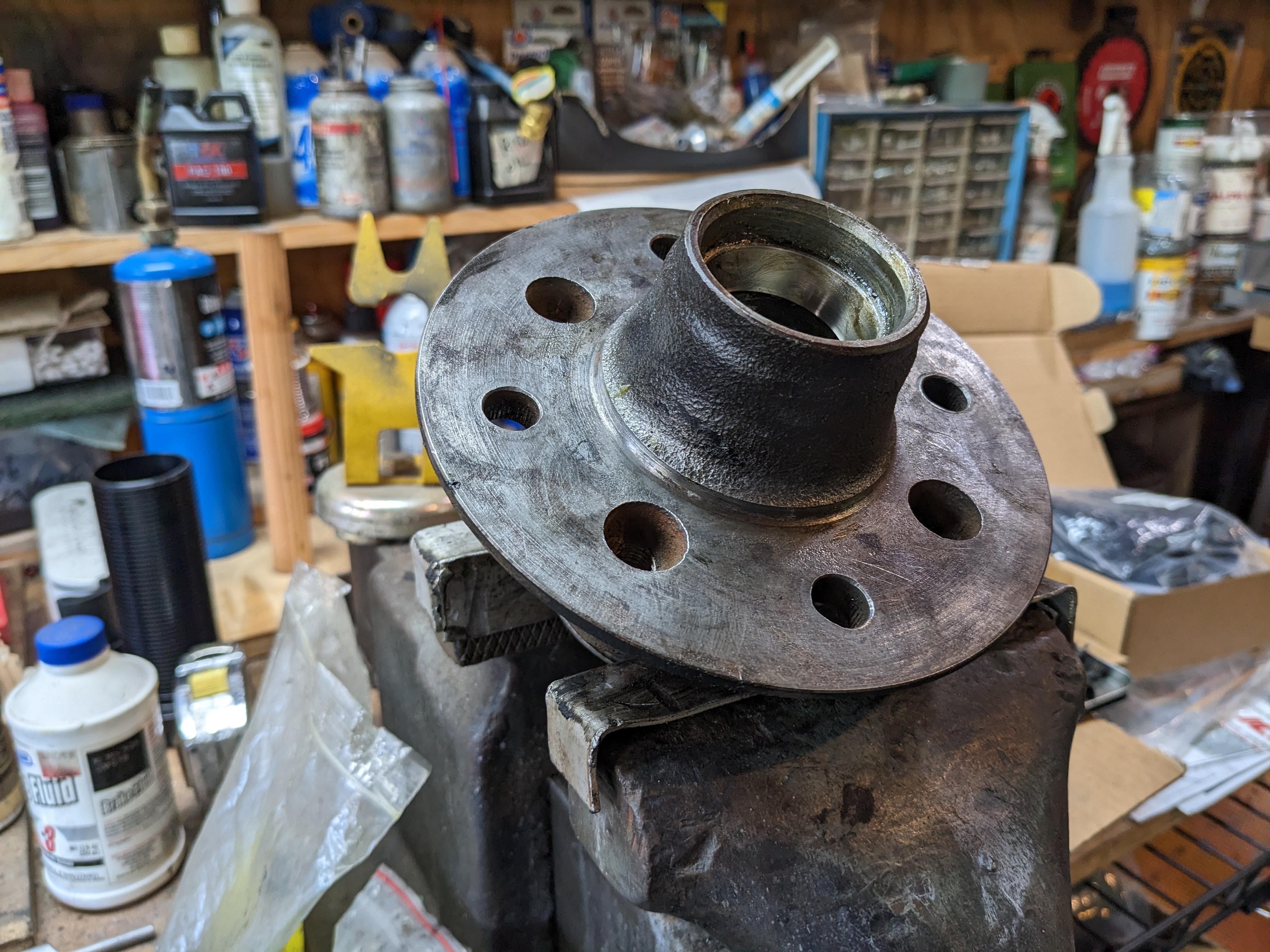
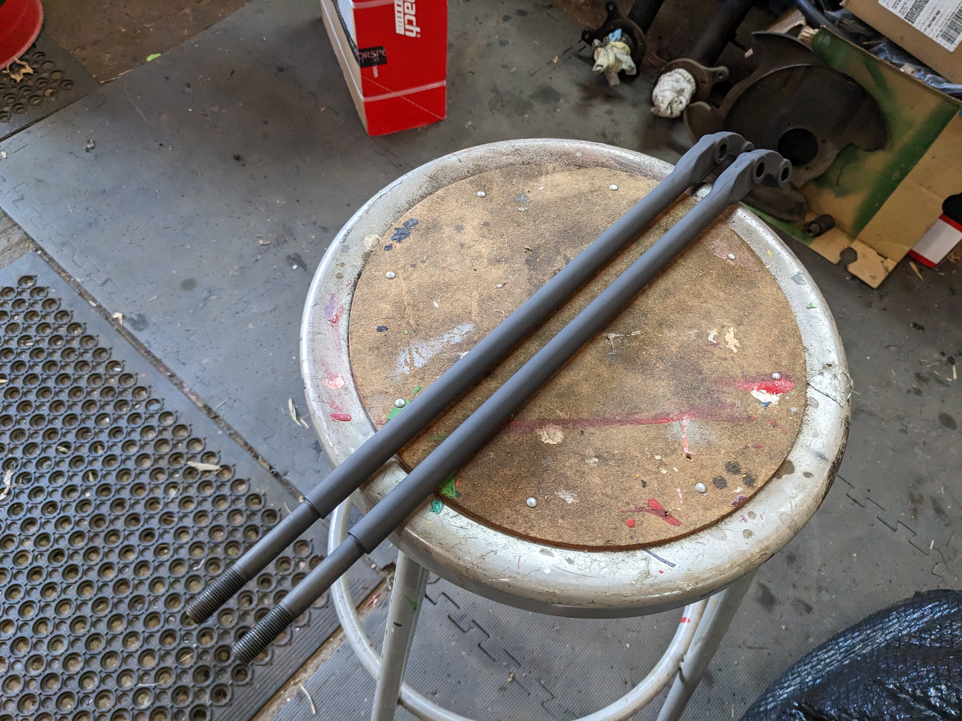
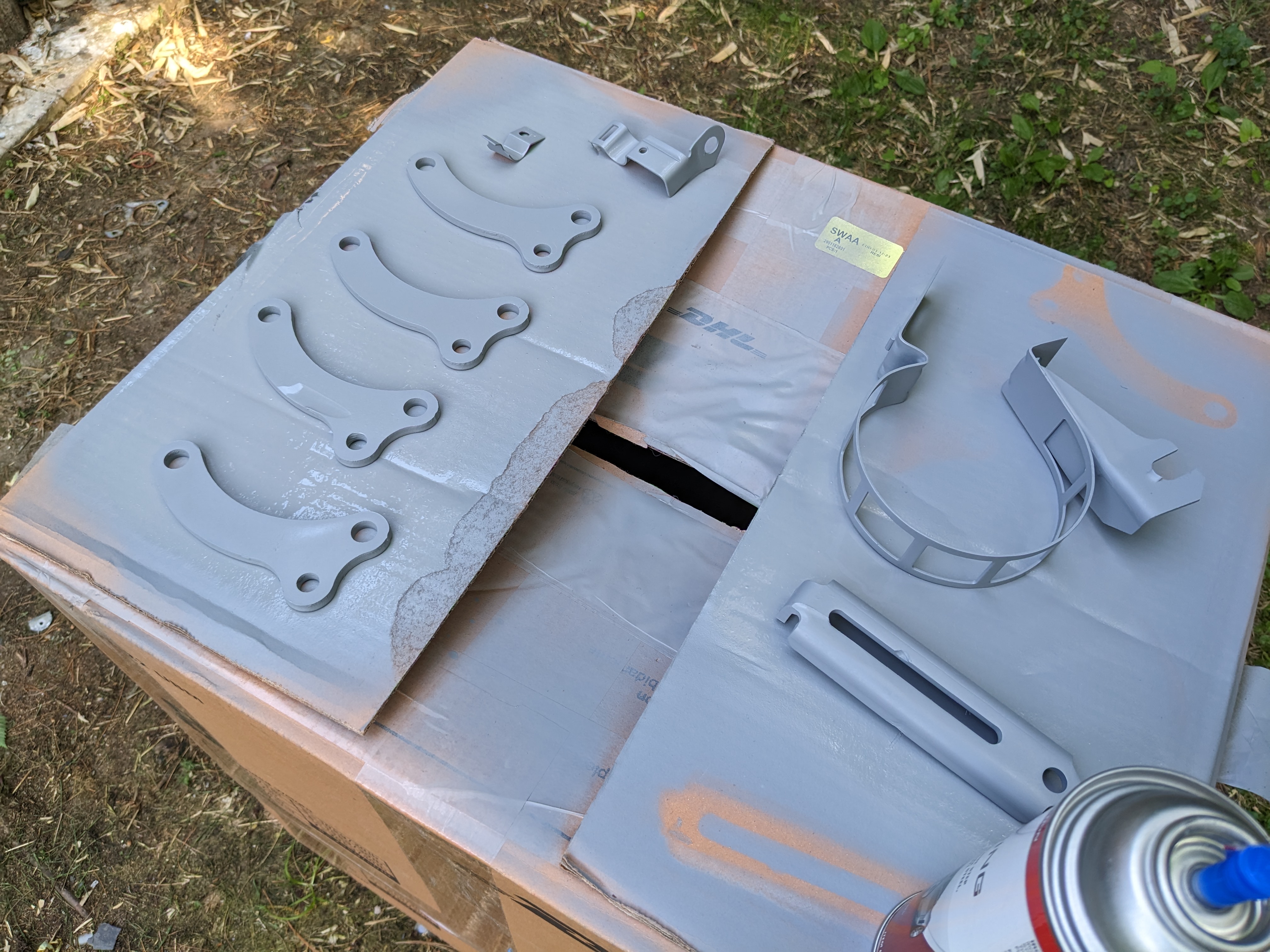
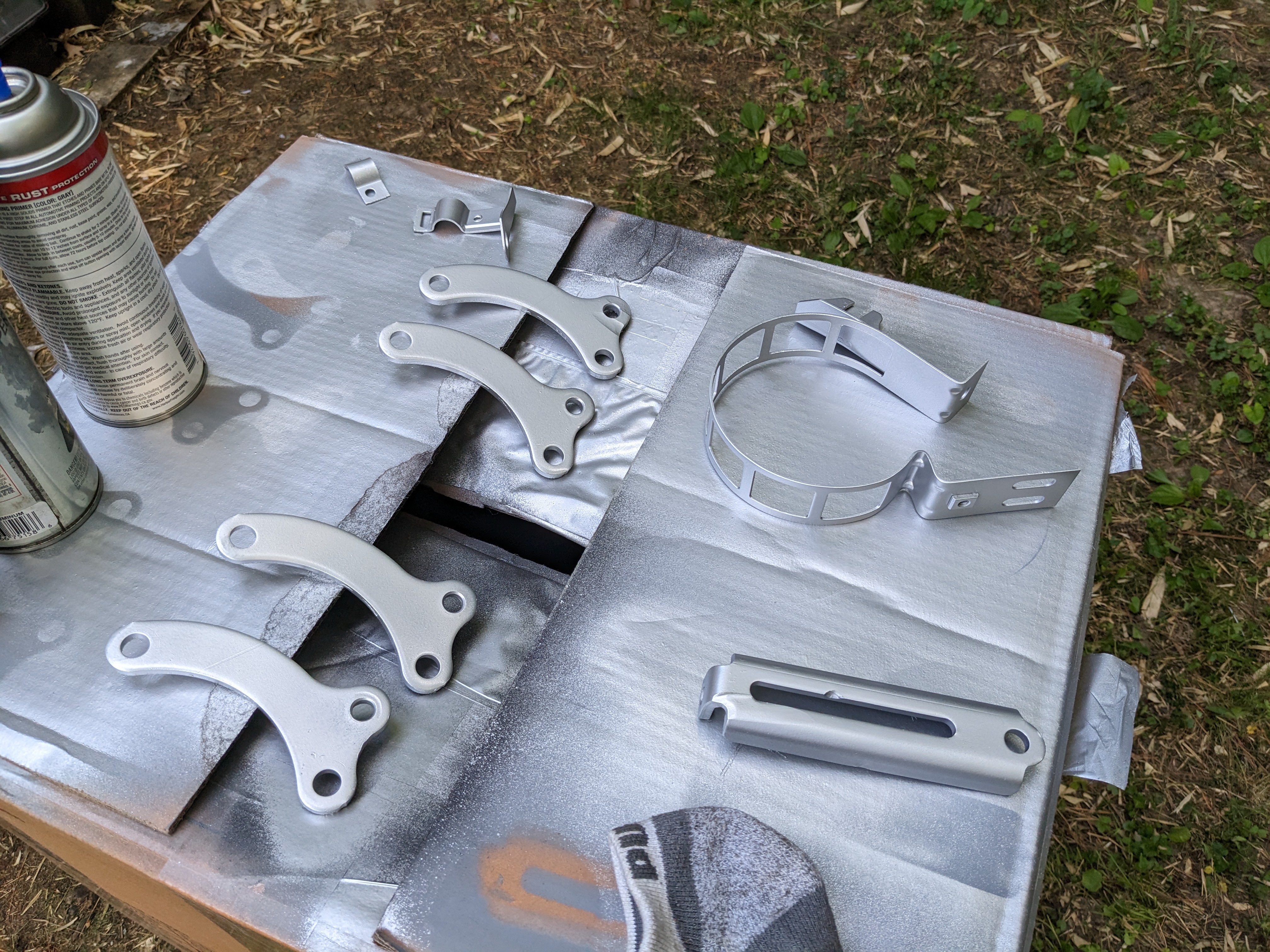
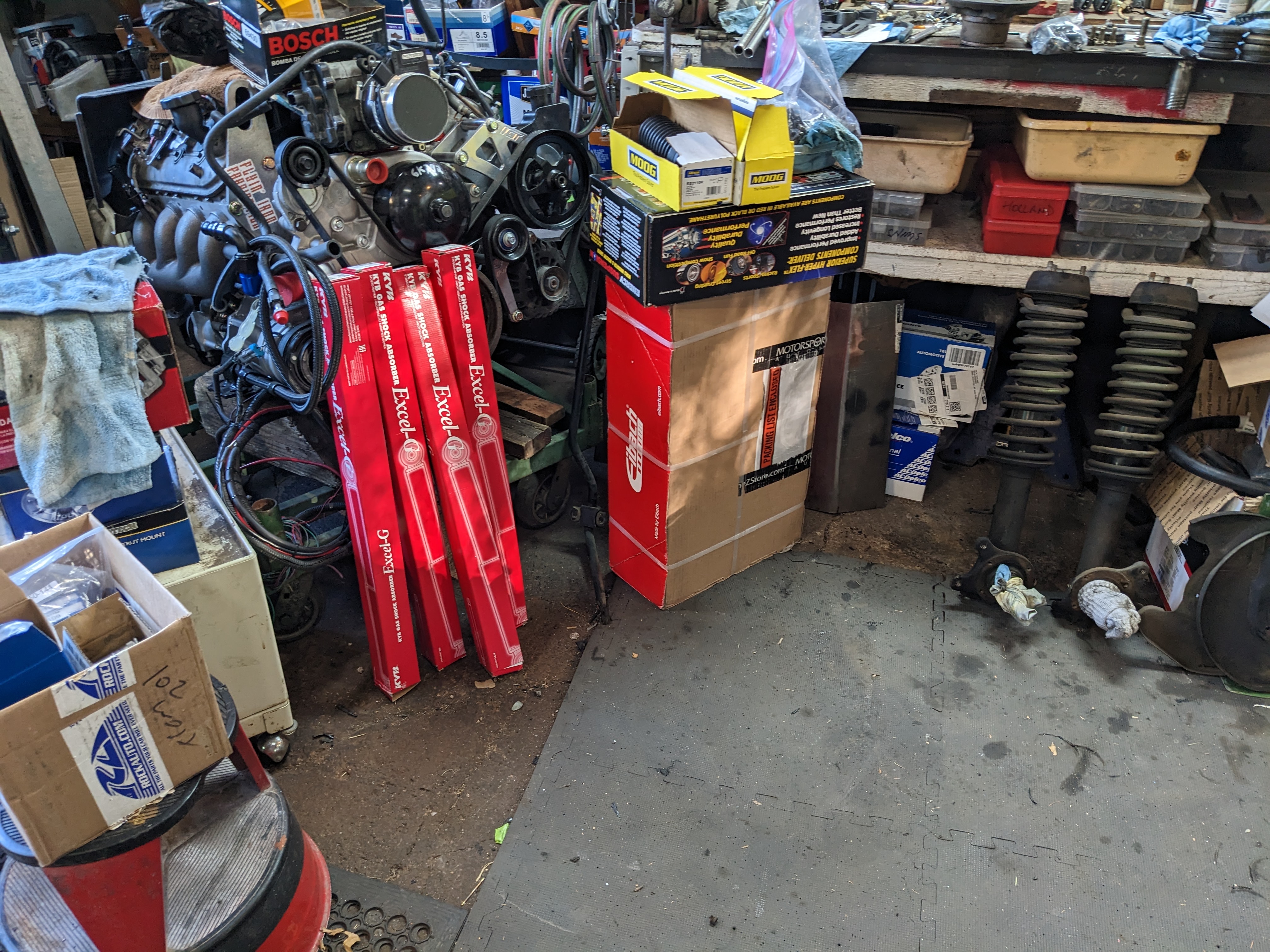
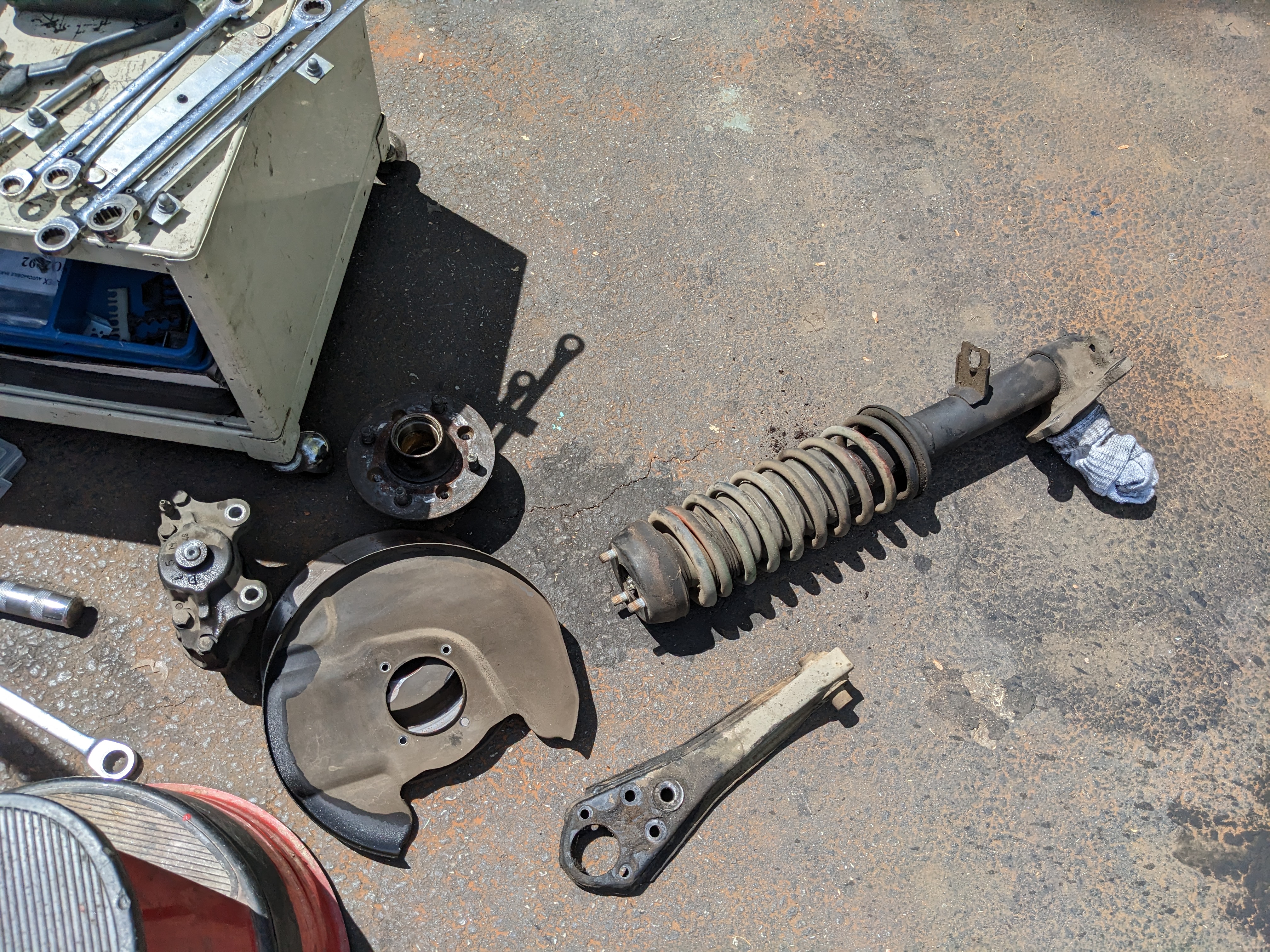
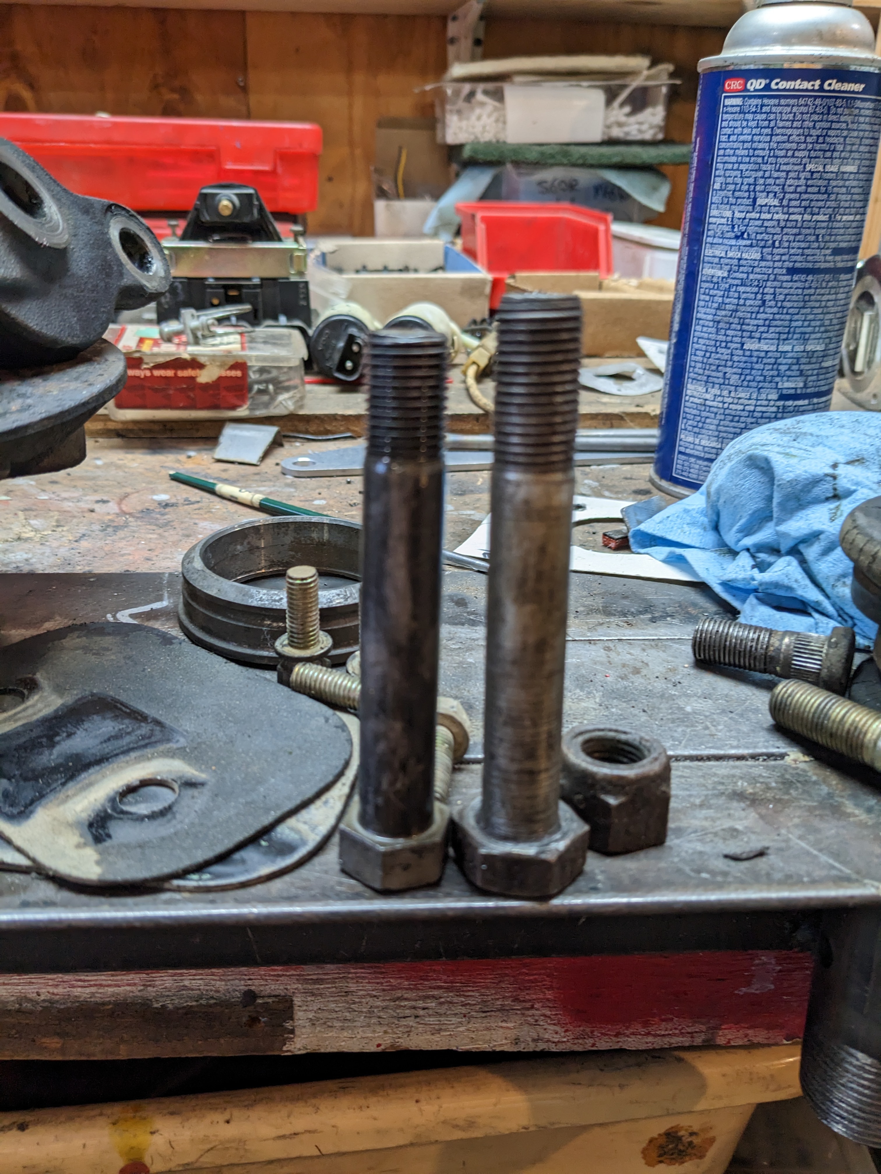
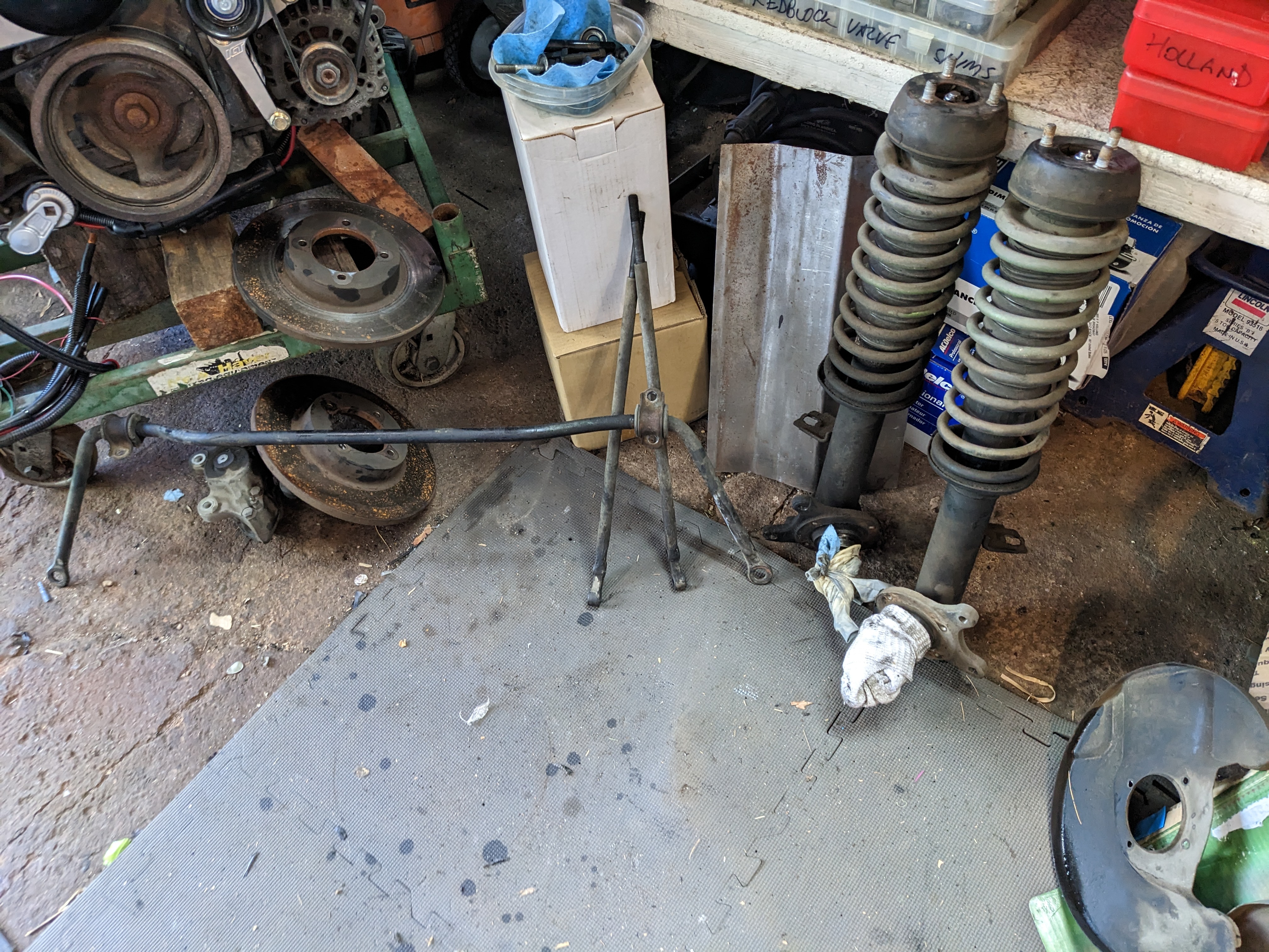
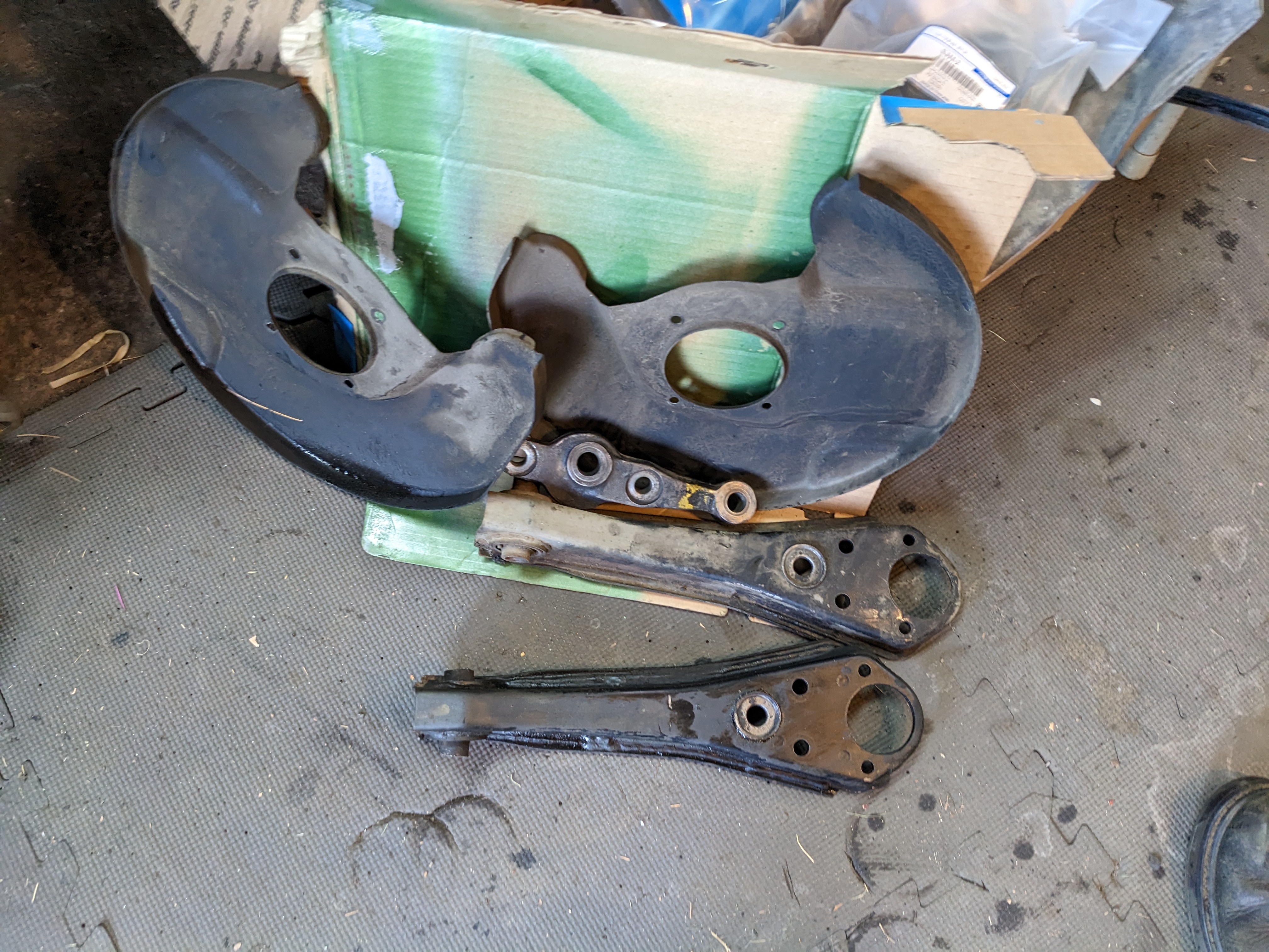
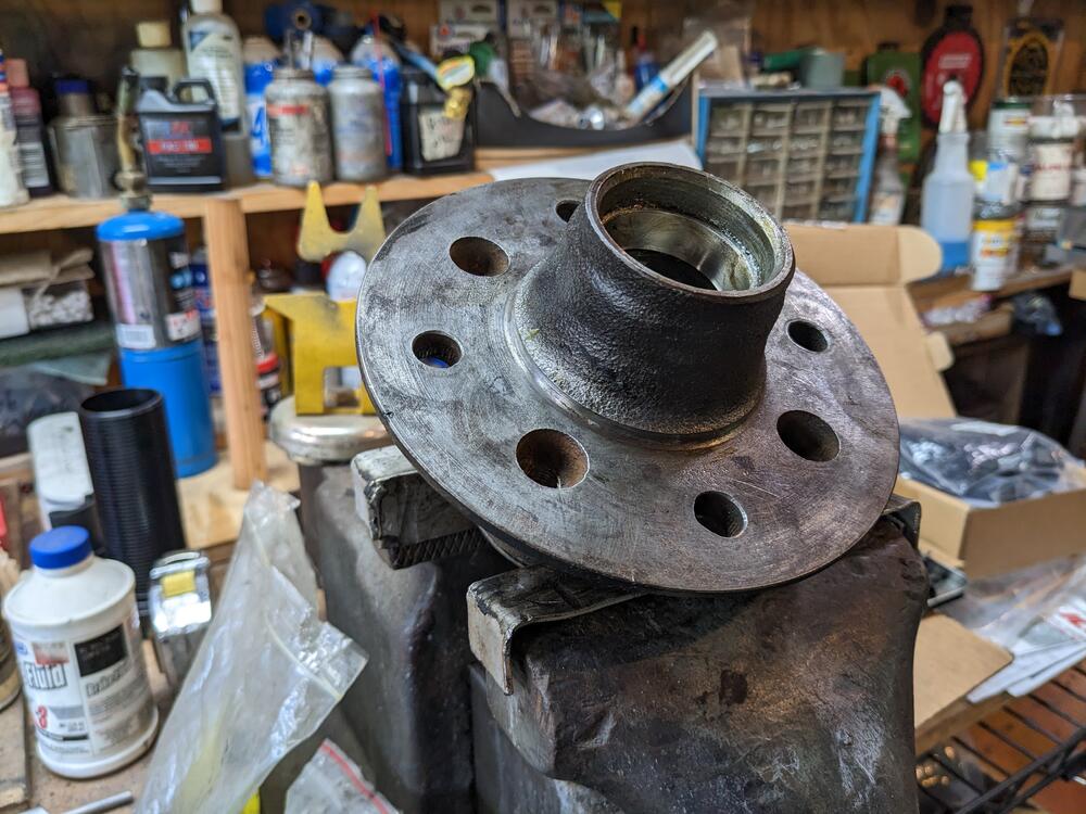
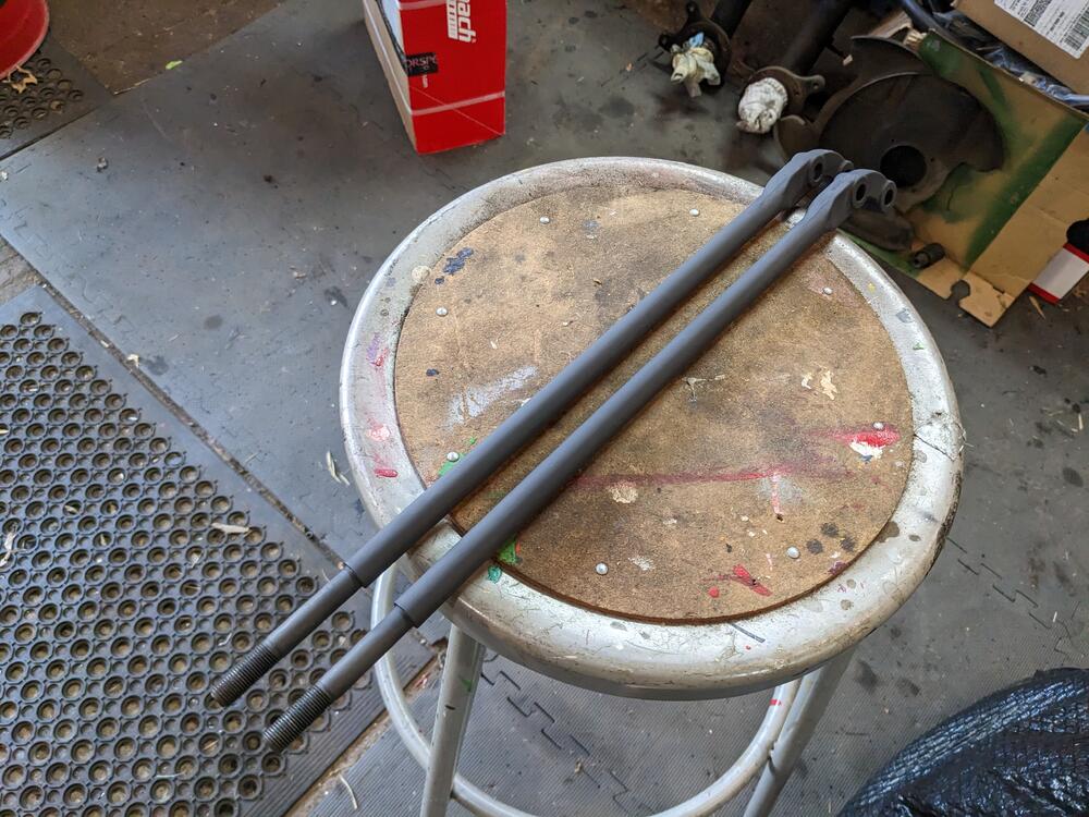
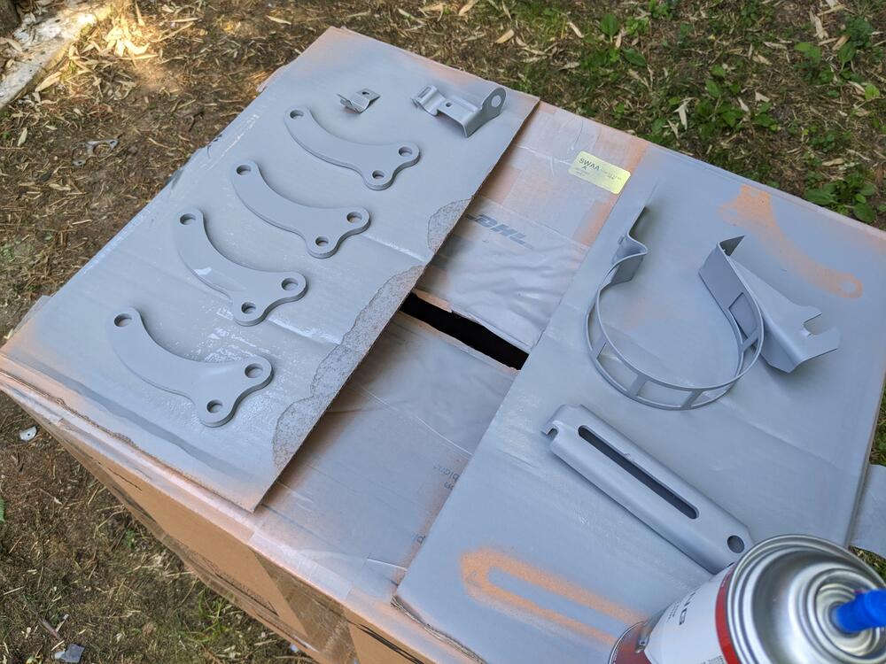
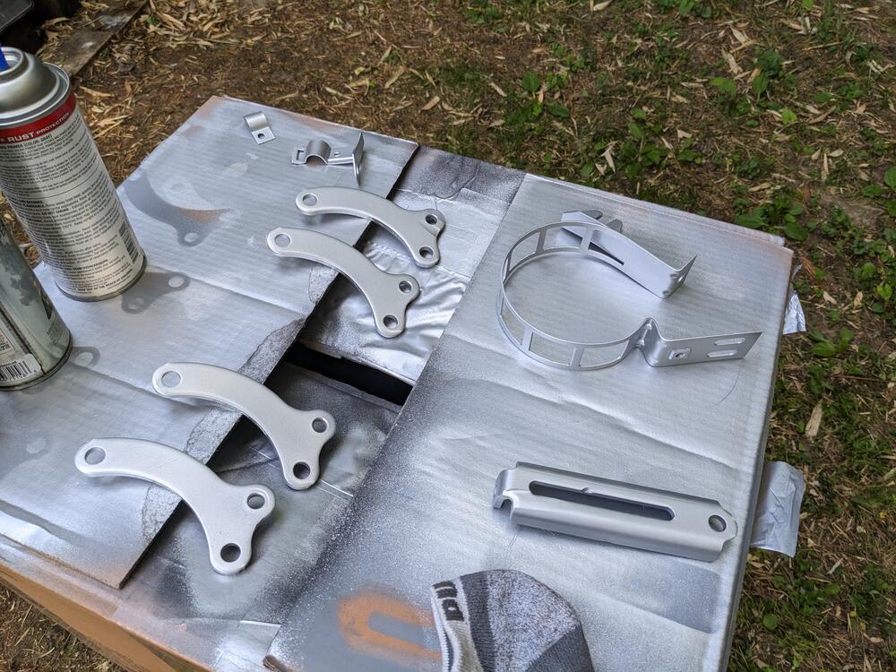
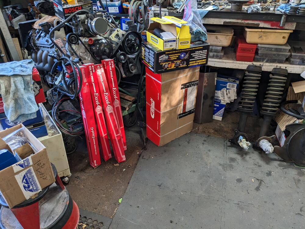
Still focused on getting things set up for my mother's change in health, so not much time for the car right now. I got about an hour to futz, so I started cleaning up the front hubs and tension rods, and acid-dipped, cleaned, primed & painted the AC compressor mount brackets (for the Volvo conversion) An array of suspension & brake parts
-
Nice find! I messaged him on FB, to ask if he has 280Z templates. ZcarDepot has an Asian vendor, but they have no stock or ETA on 75 280Z pattern
-
Nice work! Always good to rebuild when possible. It's better to problem-solve & find a solution vs. just replace If you have a selection of AC orings, for example, the thick wall variety would probably seal, since it's just the seat, not the sliding seal. I doubt that square cut is an imperative, if one cannot be readily sourced.
-
-
I haven't, but my question would be how you are going to replicate the factory stitching / door panel design. IMO, flat stretched vinyl without the design/detail element is going to look pretty tacky, especially considering the labor intensive nature of the job. Another consideration would be the state of the door card itself. Unless it's really pristine & all mount points have no water damage, that will be another detractor when it comes to assembling the vinyl to the card. Do you have any experience sewing/ working with vinyl & patterns? It's no small undertaking.
-
-
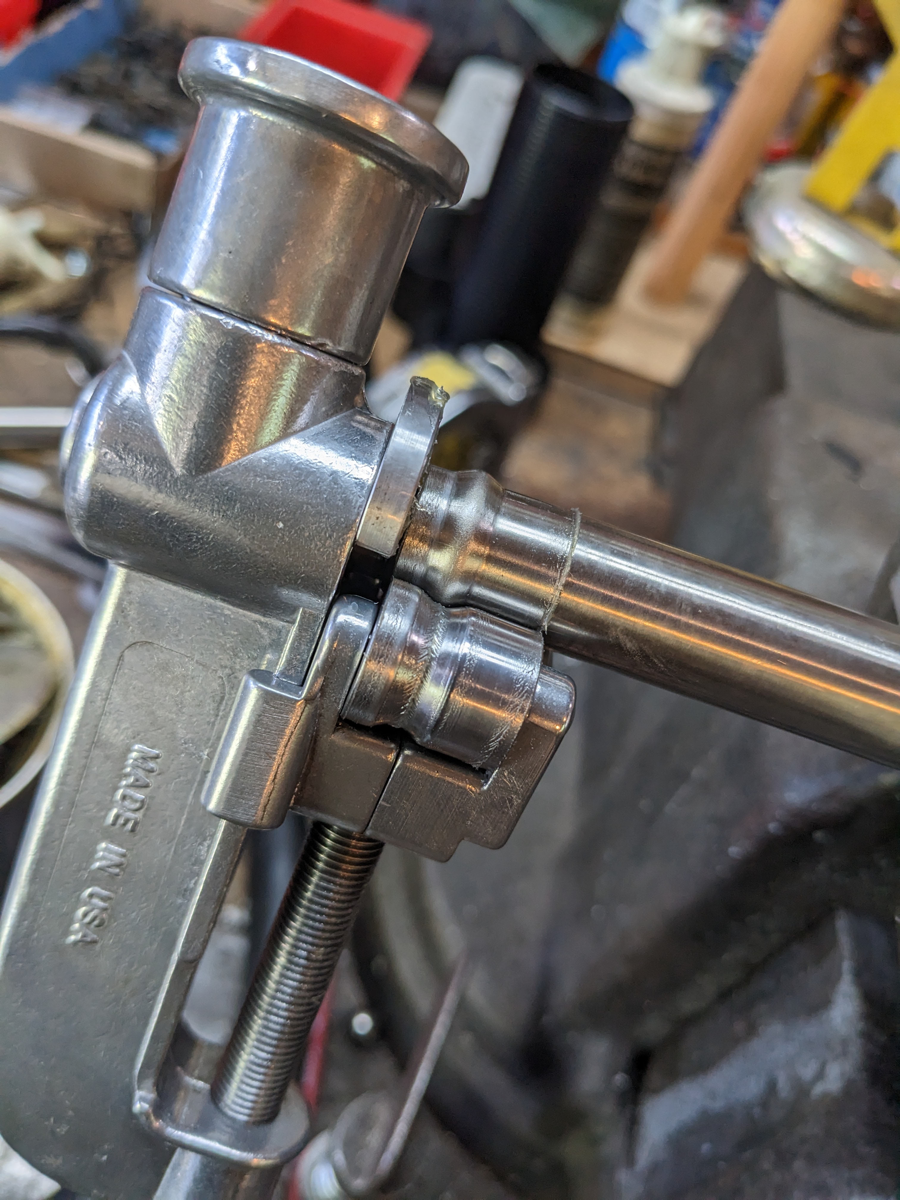
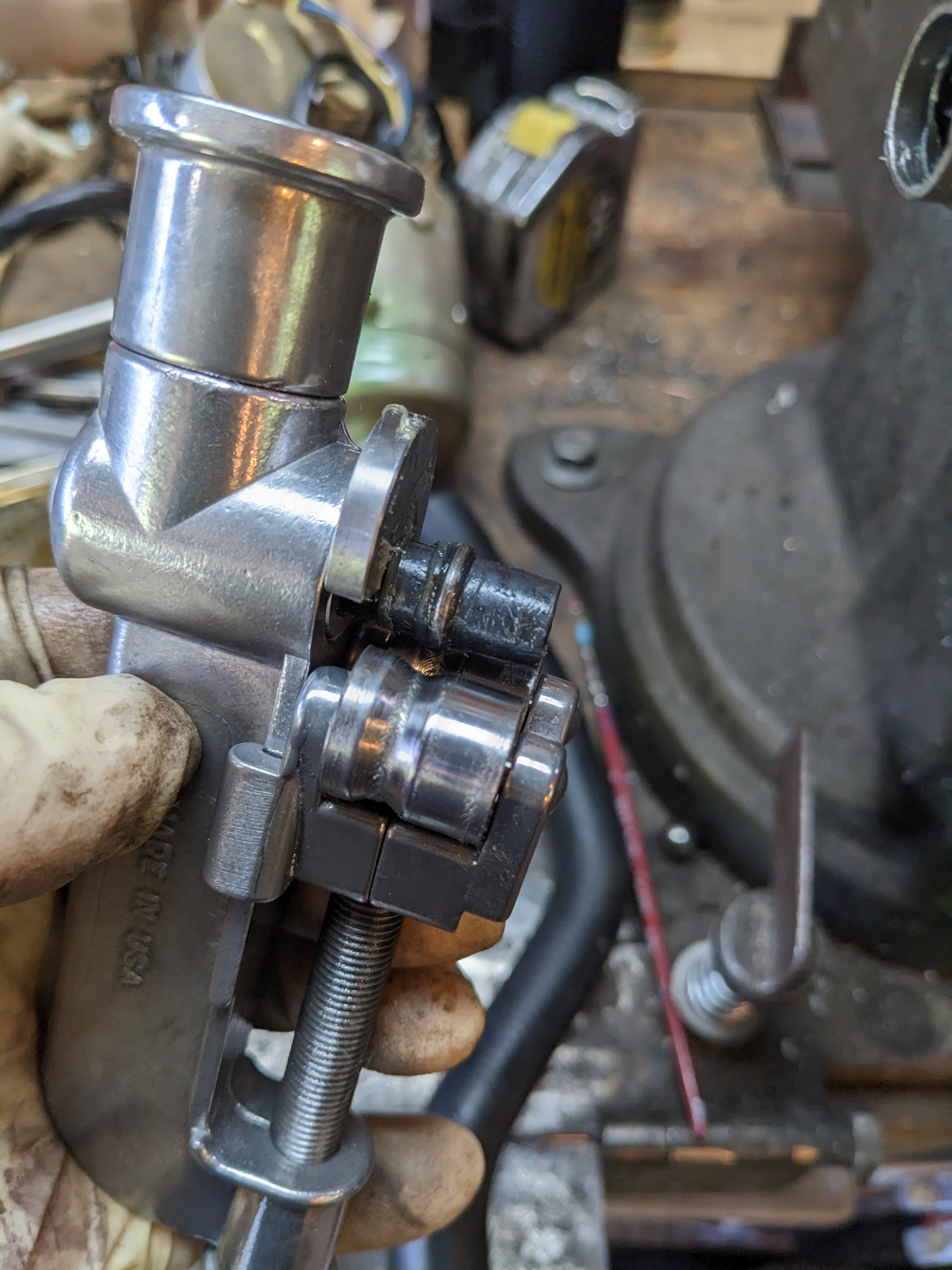
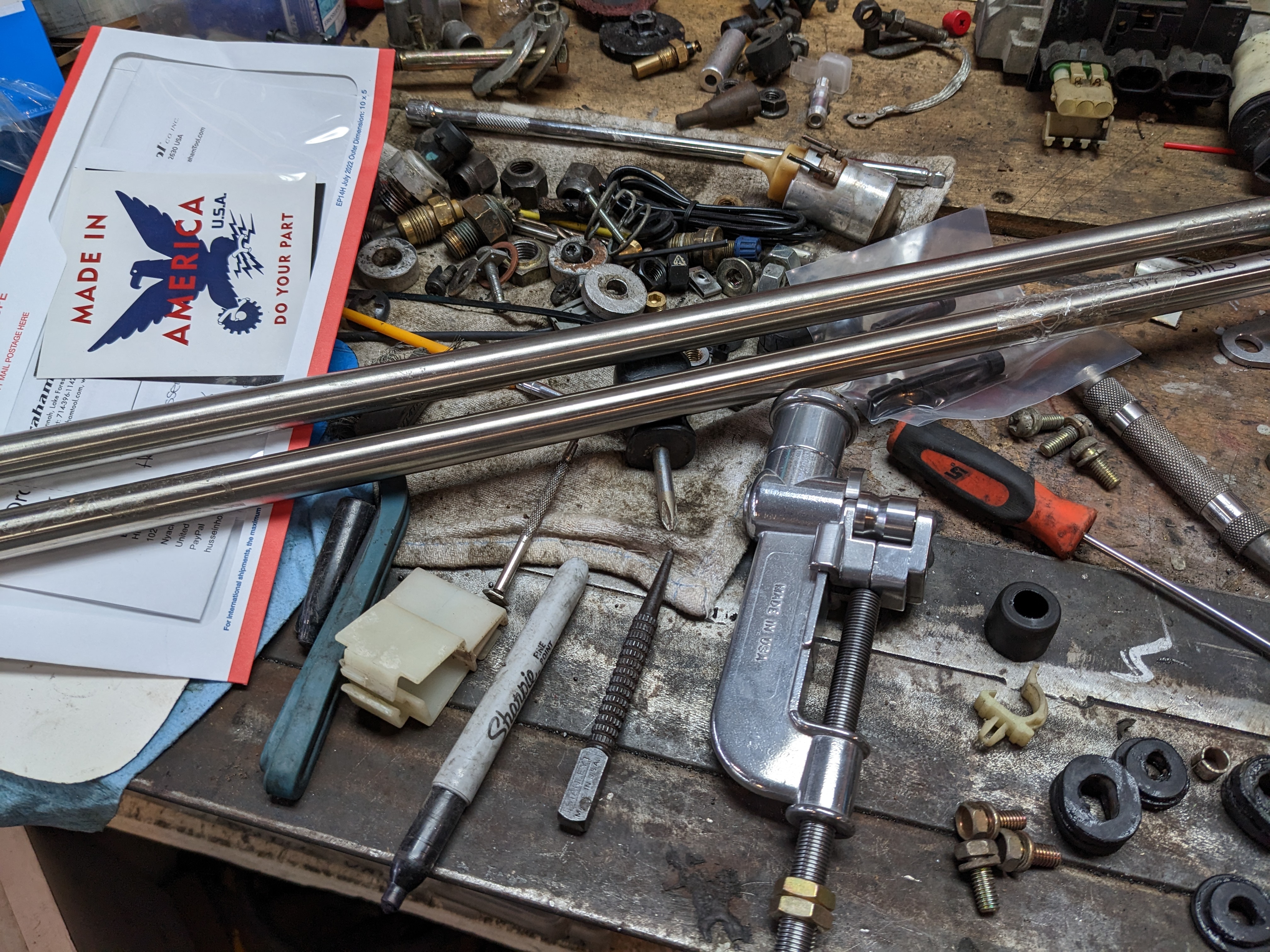
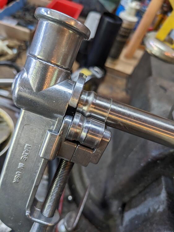
Graham Tool Co - Medium Tube Beading Tool Not cheap by any stretch, however I'll need to do a fair amount of tube bead rolling on the V8-into-Volvo-Pickup that I have underway
-
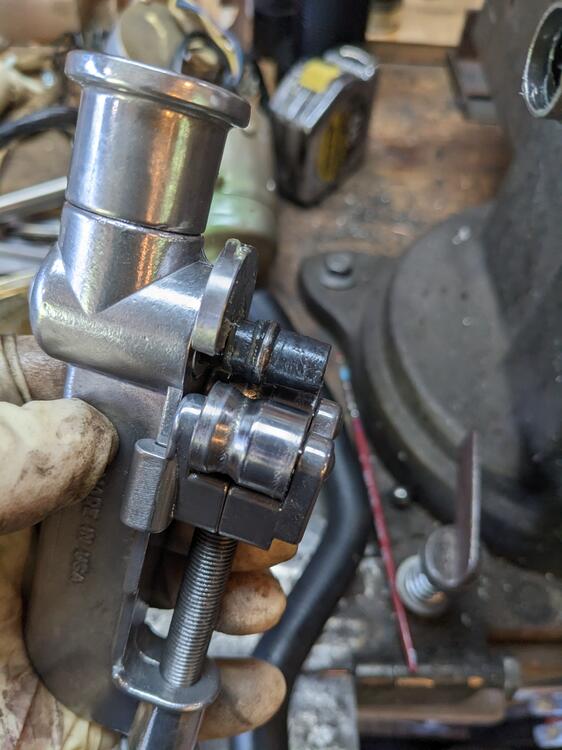
I tested the bead roller yesterday. I wish I had room for a lathe, there is certainly many an item I could use one for. In any event, this tool works very nicely
-
Hmm... that diagram shows is in the center of the dash, isn't it in the relay block. Bloody hell they like to confuse you.
-
Thanks for that, Steve. Dang. Why the heck would they label the same item as two components and number them differently? Just to fk with ppl???
-
Thanks Steve Intermittent Amp above - 7 wires Interval relay, 10 wires Locations of the 2 relays
-
Ok many thanks for all the responses. Sounds to me like all rubber or poly on the front side is the way to go. I don't want to damage the rod by making the outer length unable to pivot through the travel range. On older Volvos that use caster rods, they have a large bushing on the body side to allow for rotational flex over suspension travel, and the resistance bushings are set into an ear in the control arm. X1/9's are setup like the Z, with a rigid mount at the control arm and the resistance bushings at the frame, just forward of the control arm instead of aft. Those wear the bushings rapidly, in the scheme of things
-
I'm confused as the diagrams indicate two components with different pin outs for the intermittent amplifier and interval or intermittent relay in the diagrams I posted above.
-
Quick question - I know I read this in someone's post, but now it's not coming in a search. Do I want the more compliant rubber on the leading or trailing side of the frame mount? TIA
-
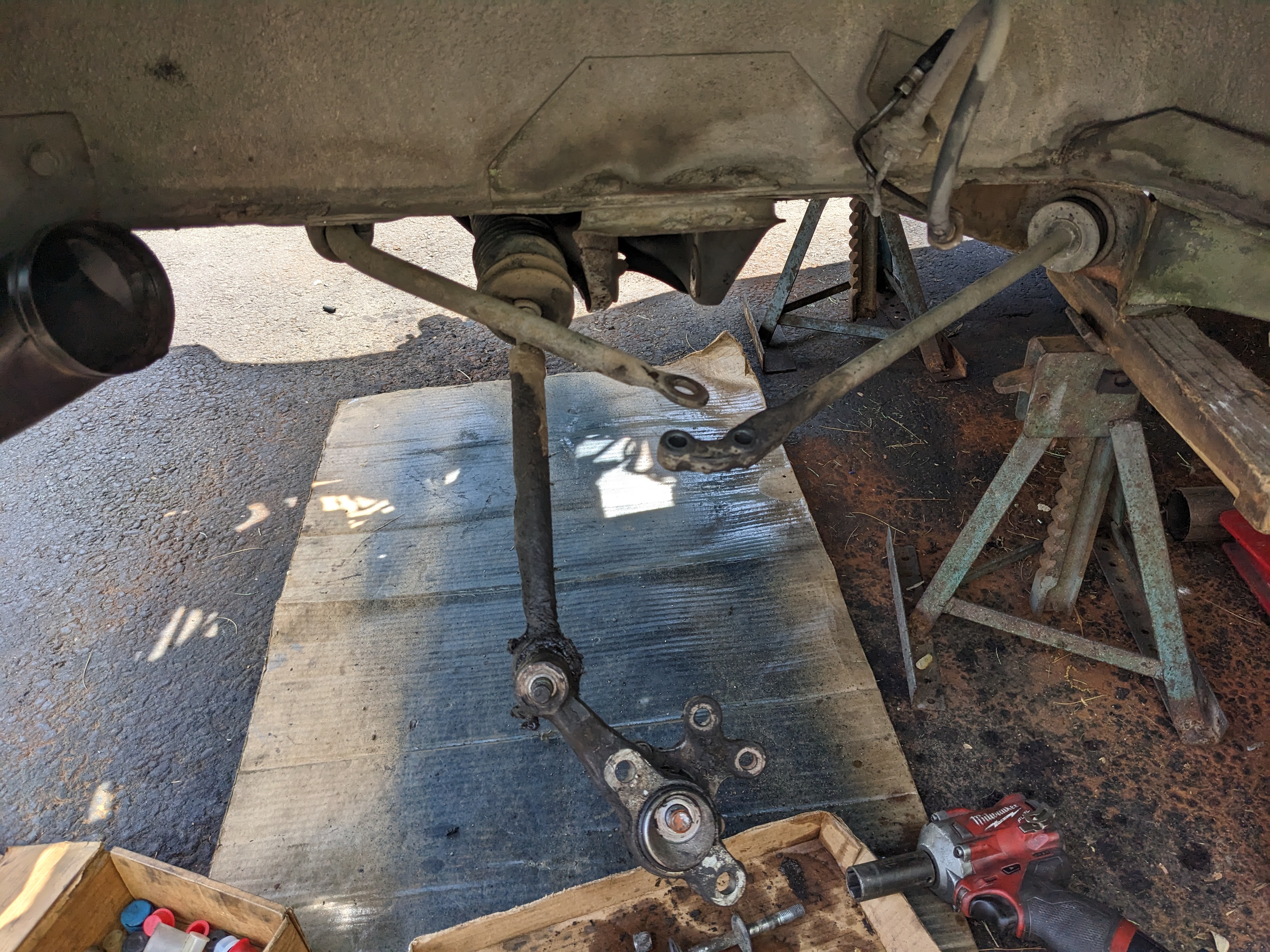
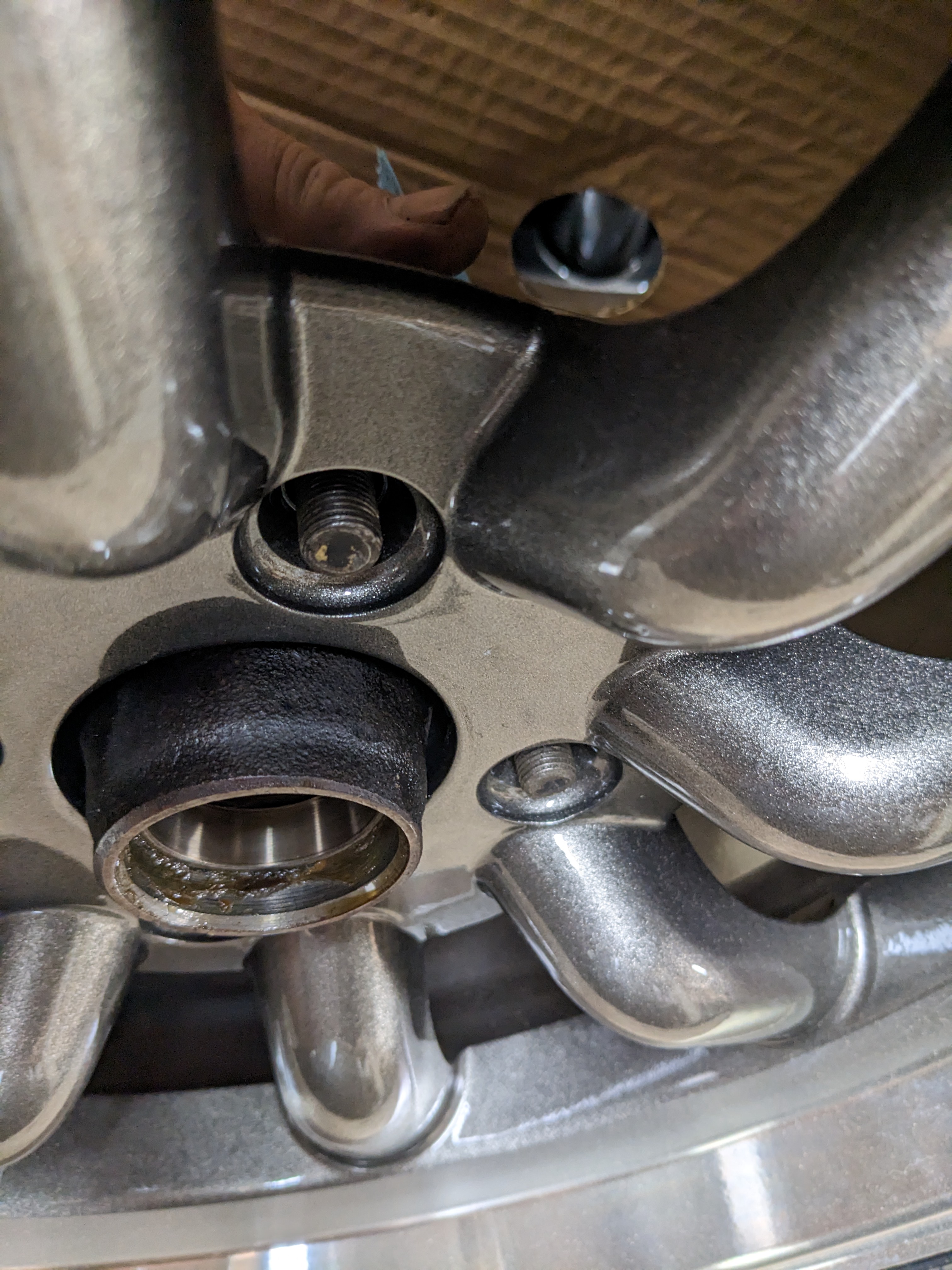
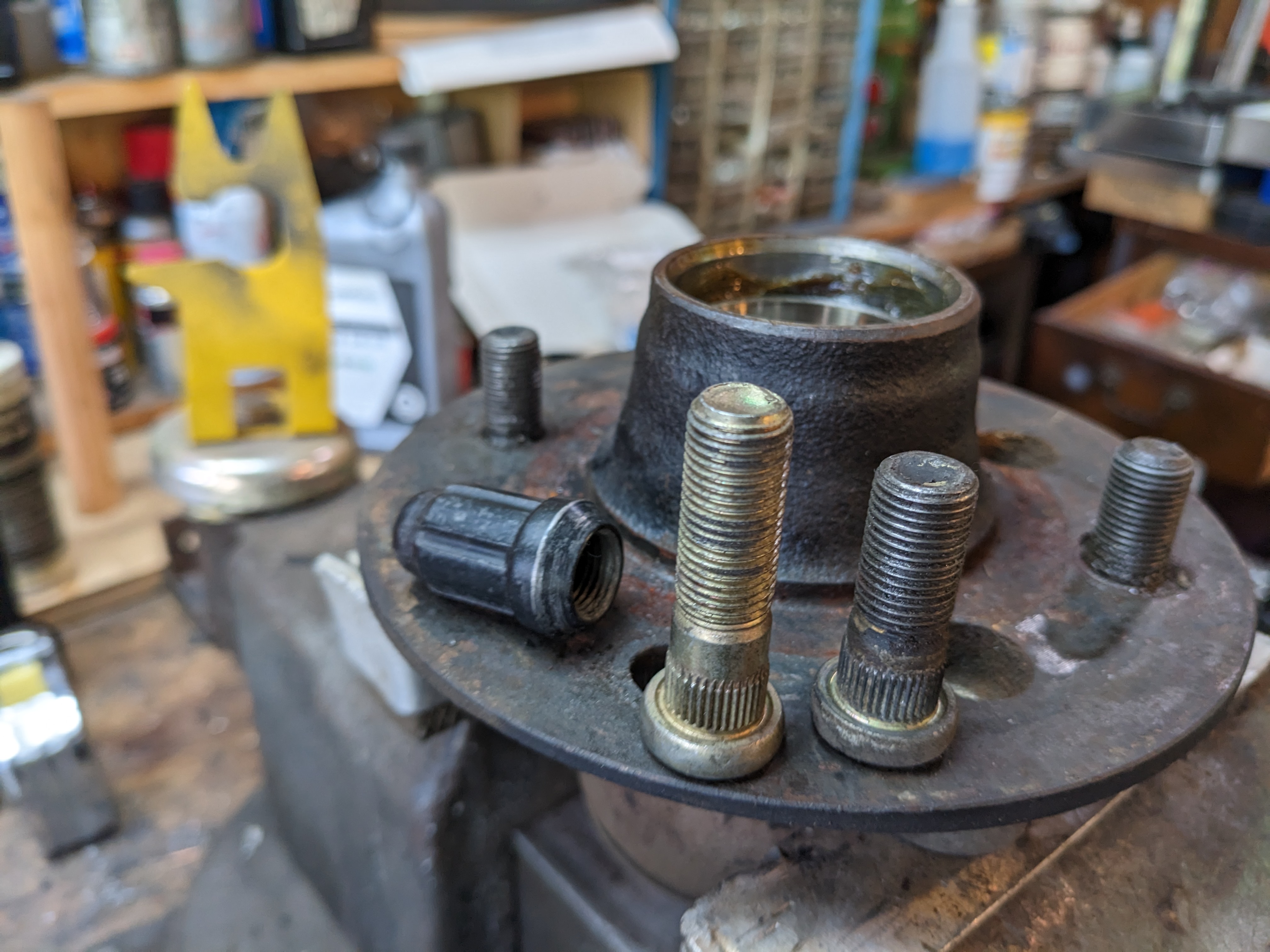
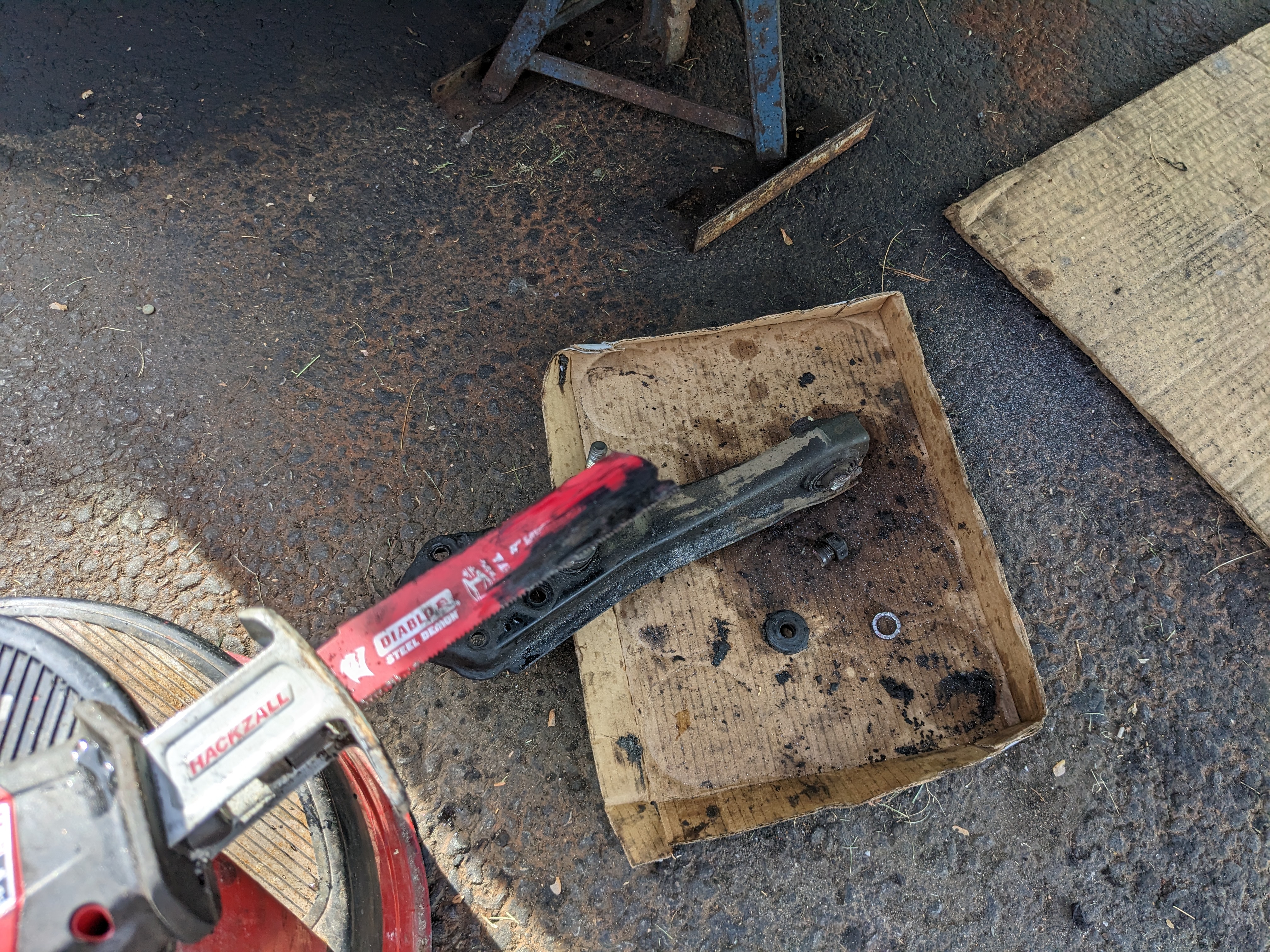
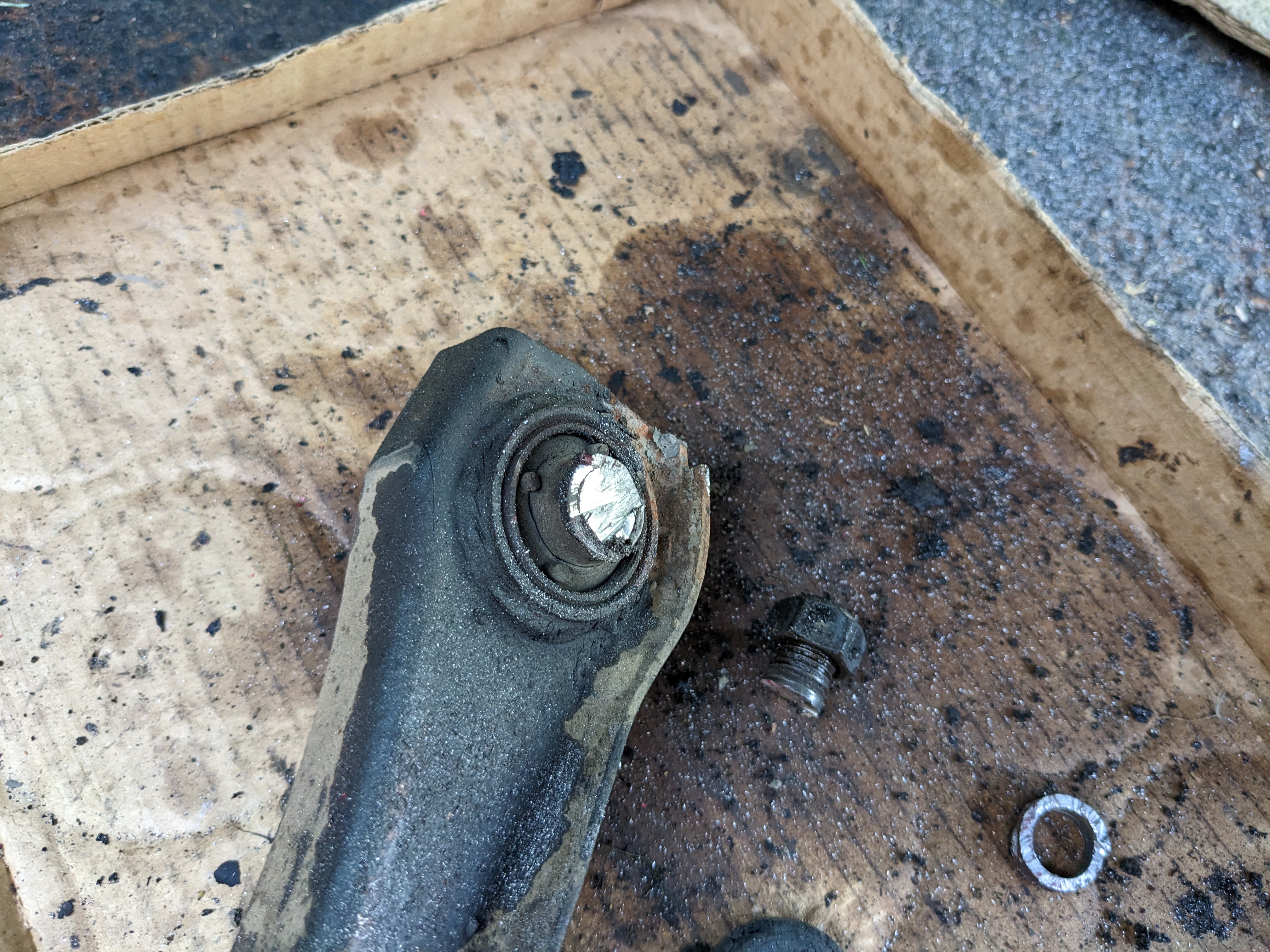
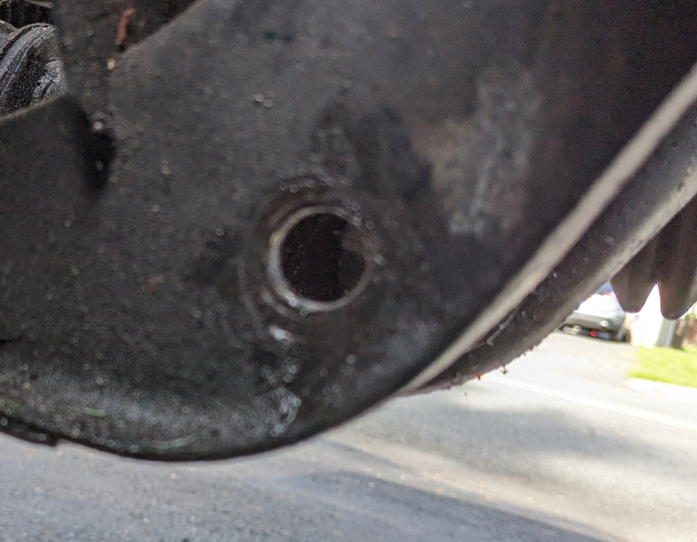
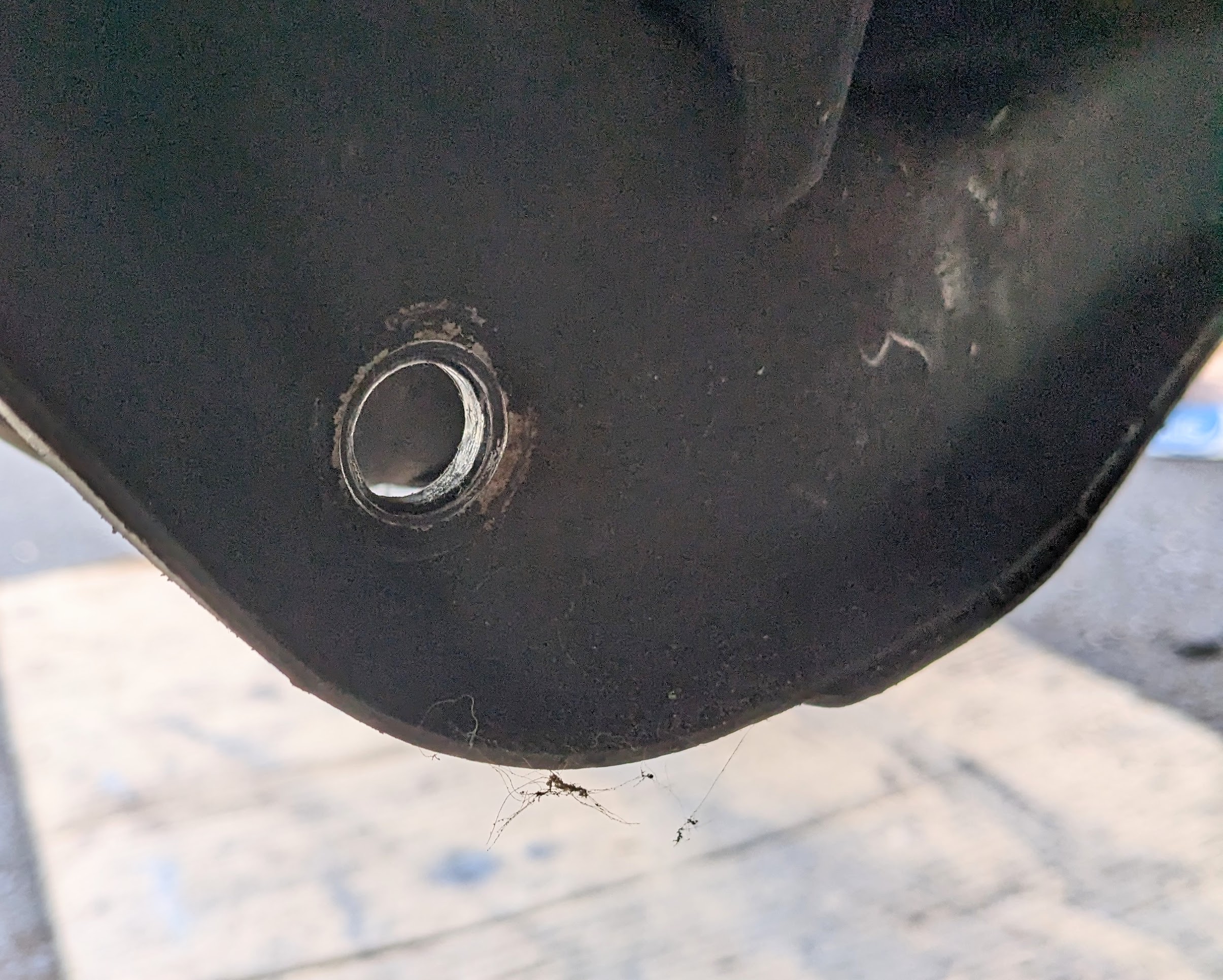
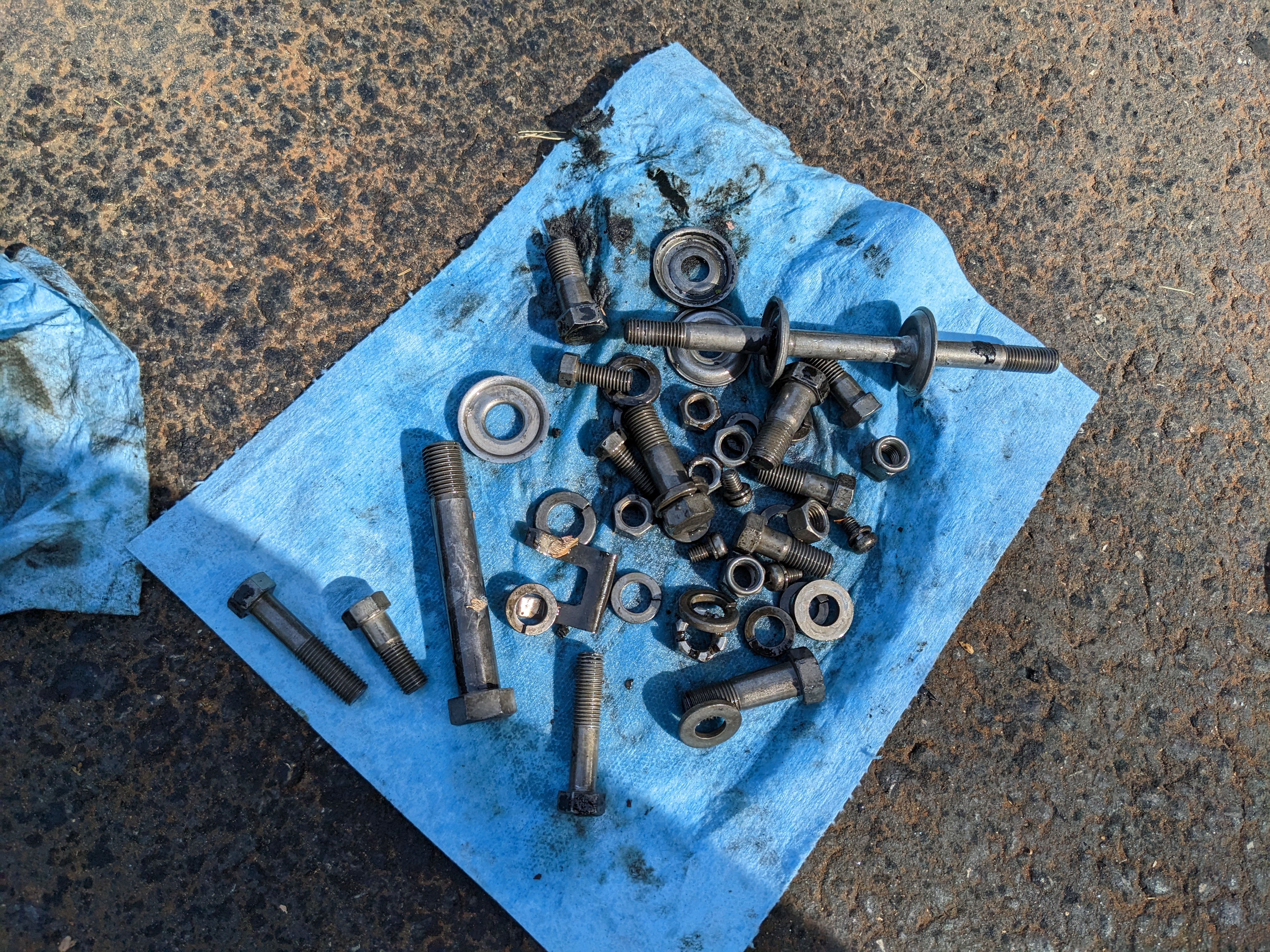
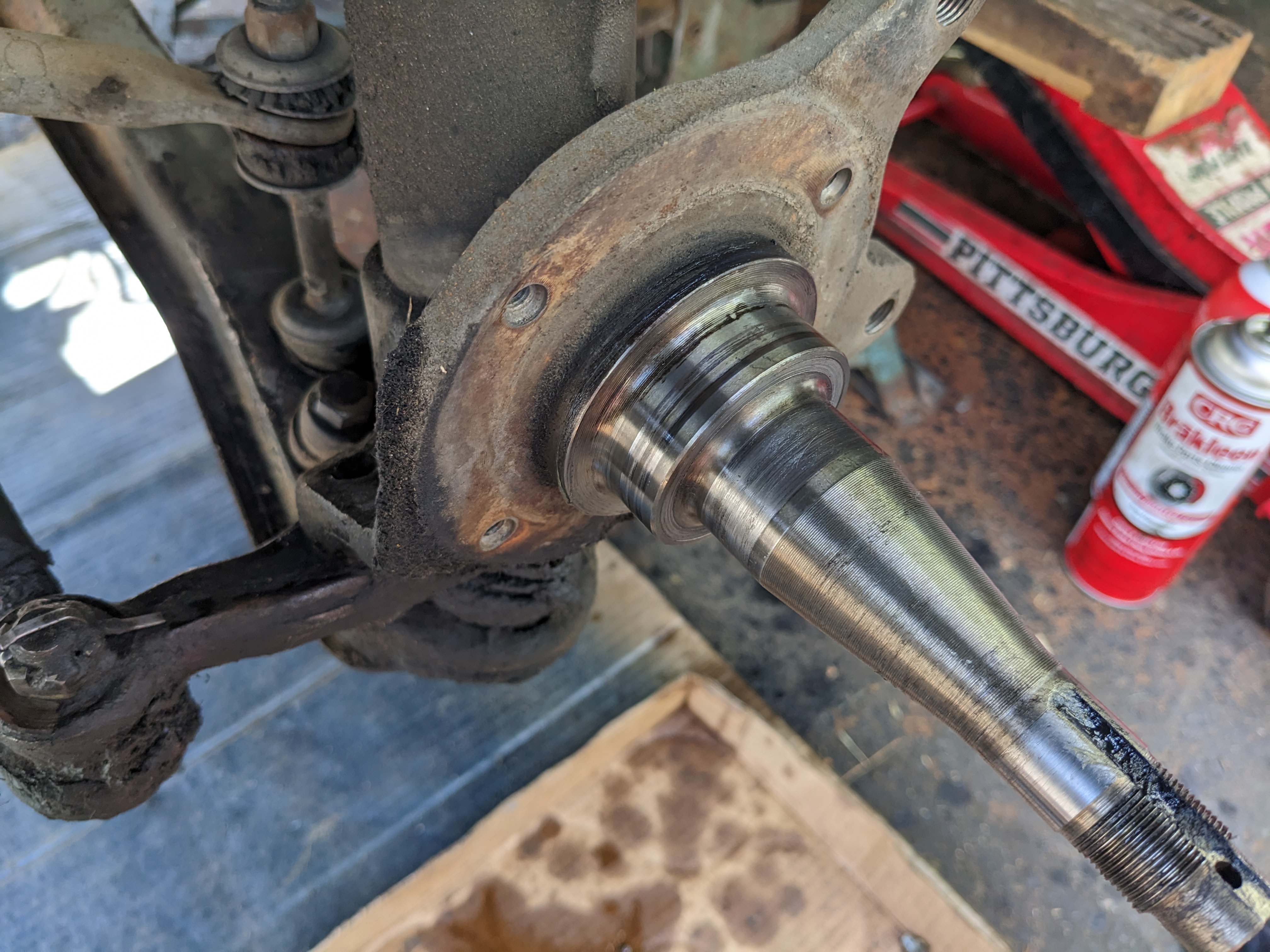
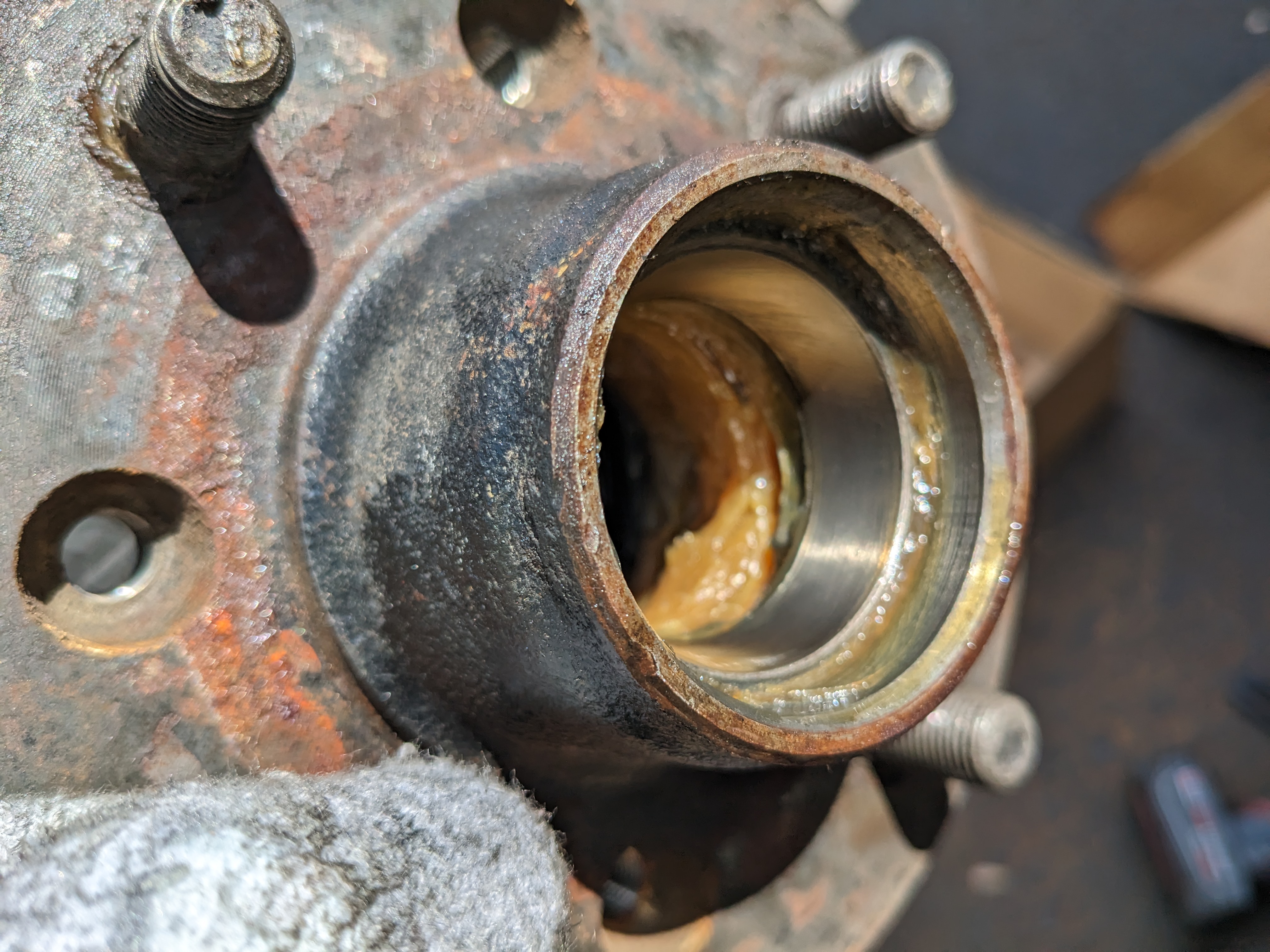
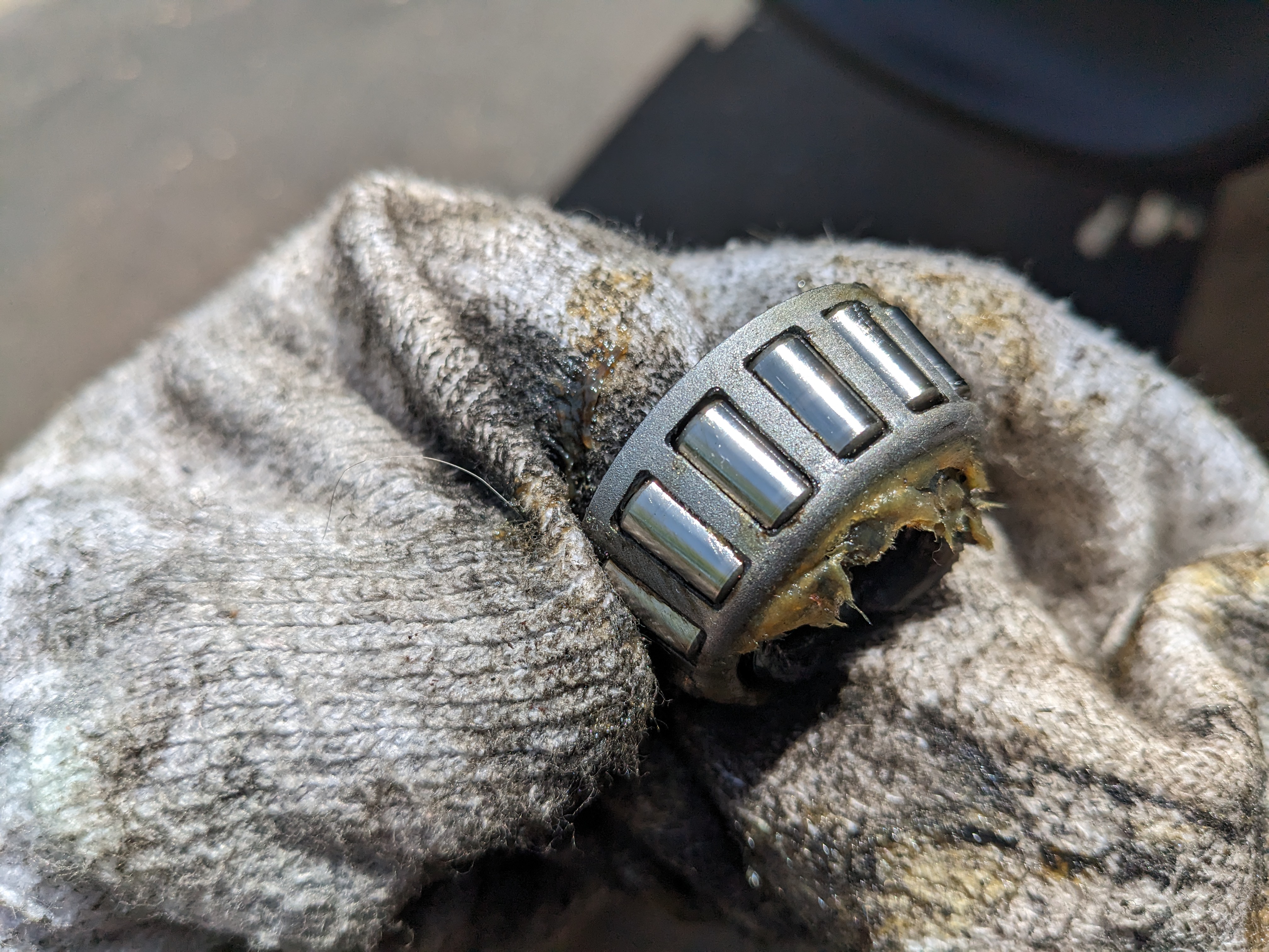
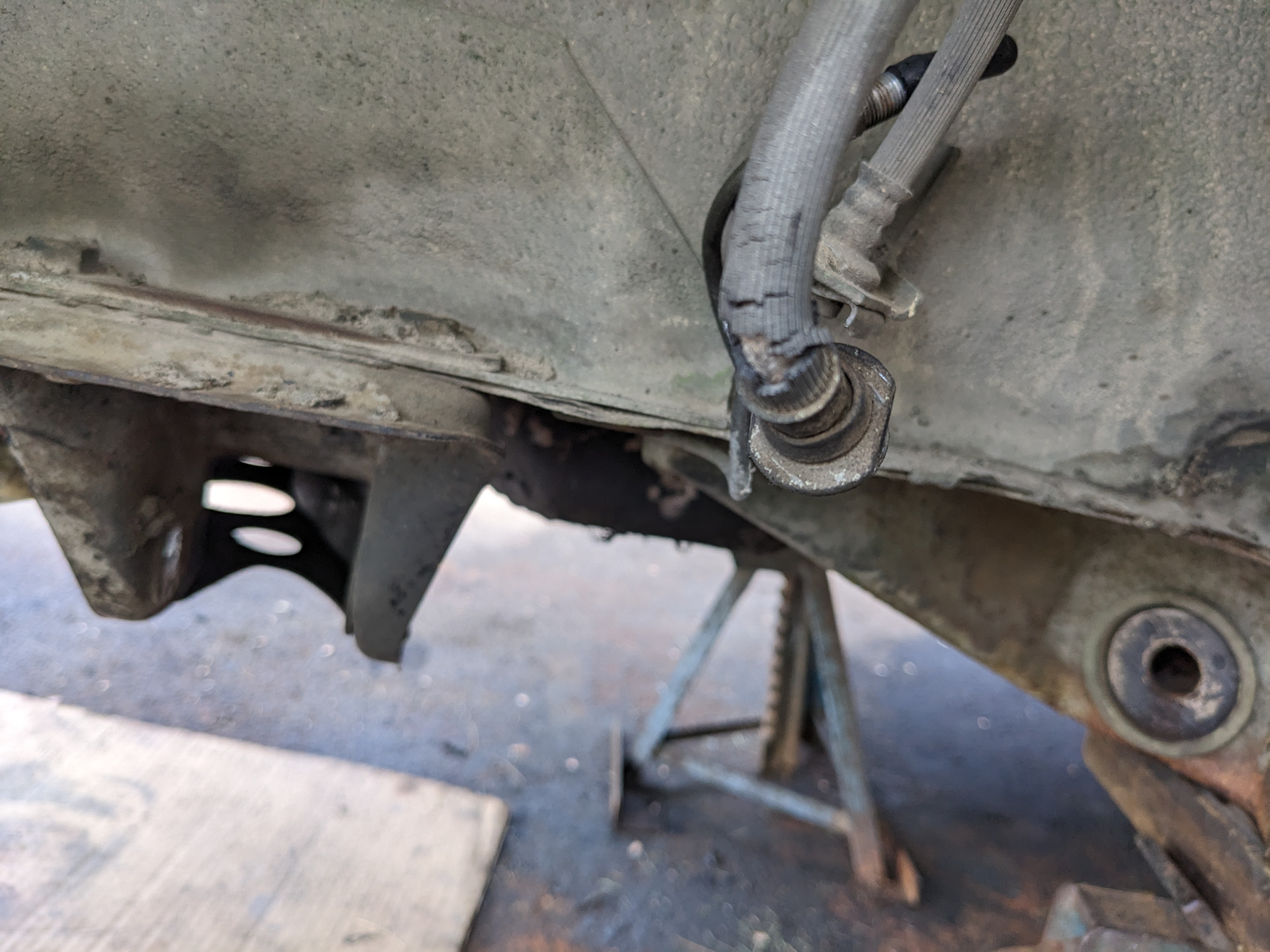
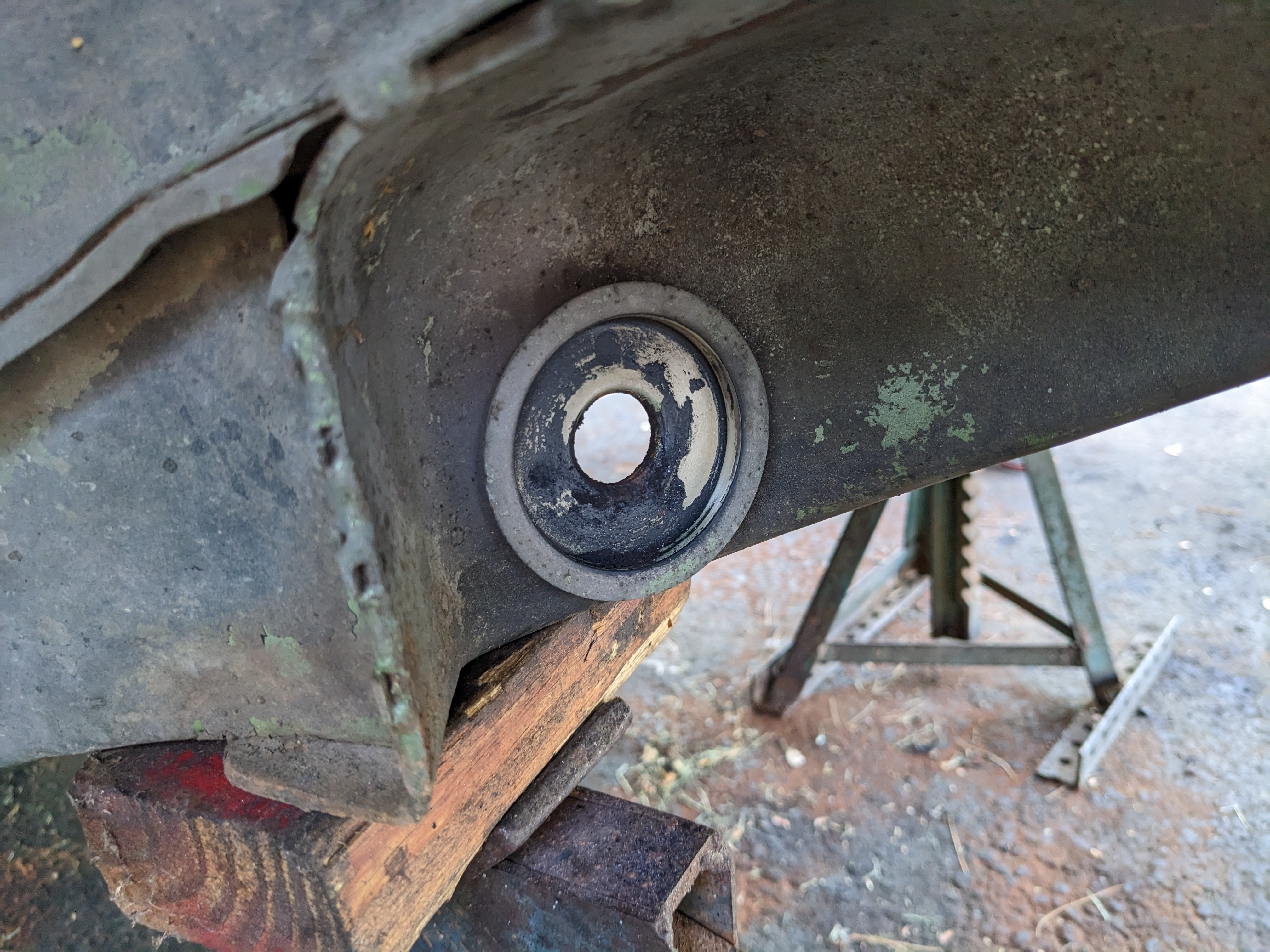
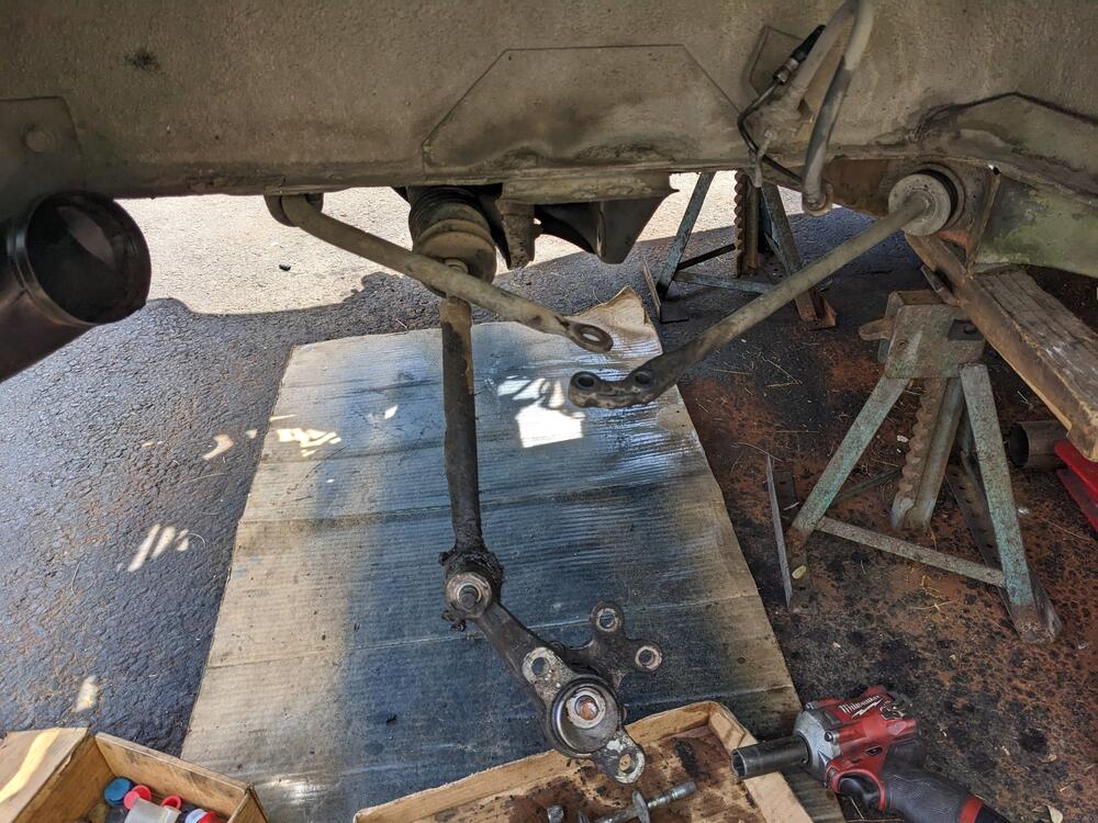
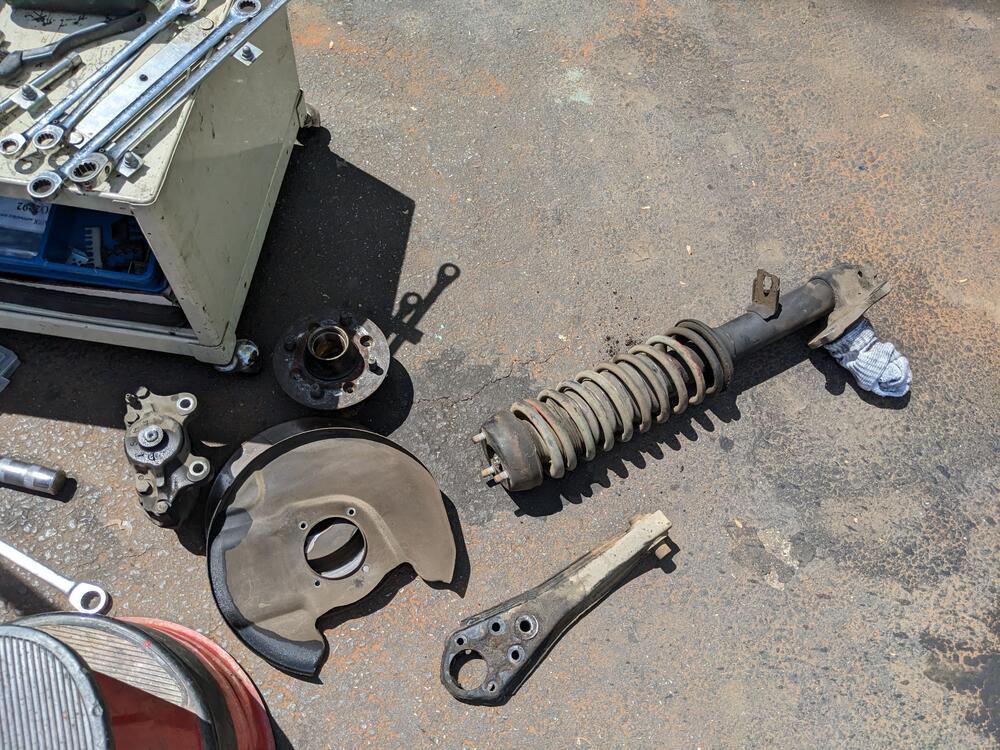
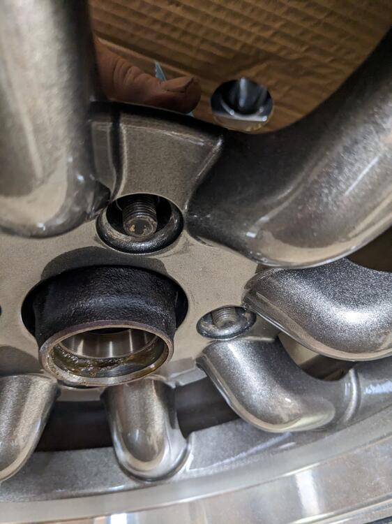
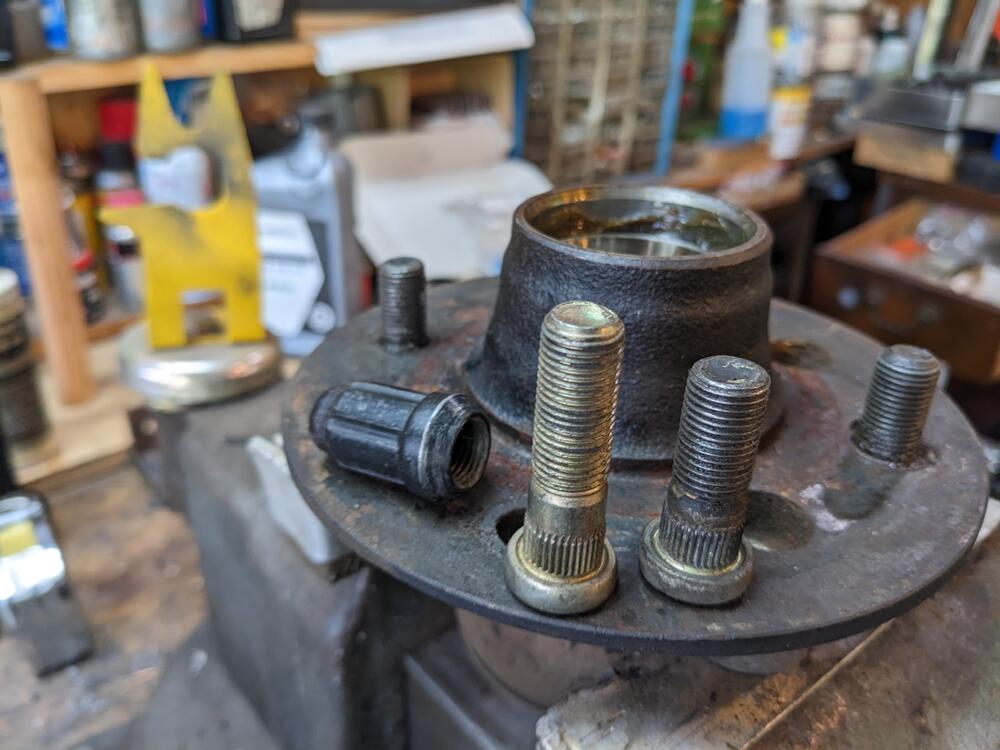
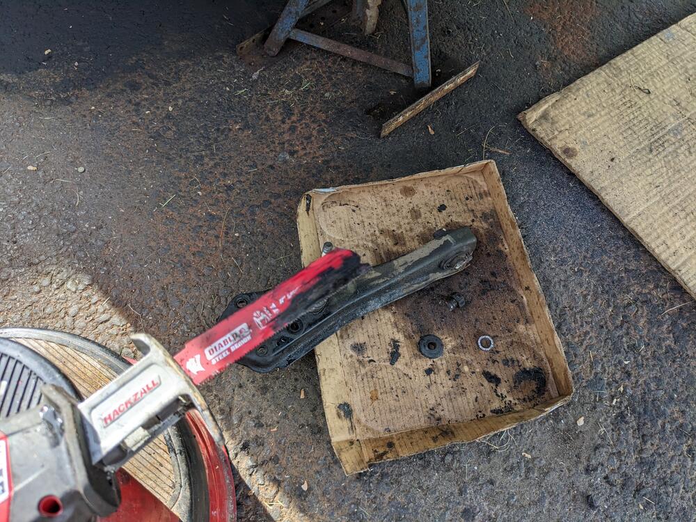
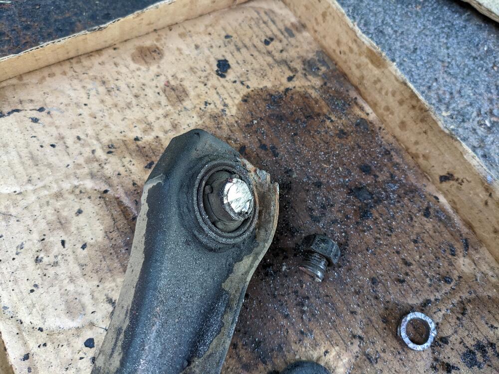
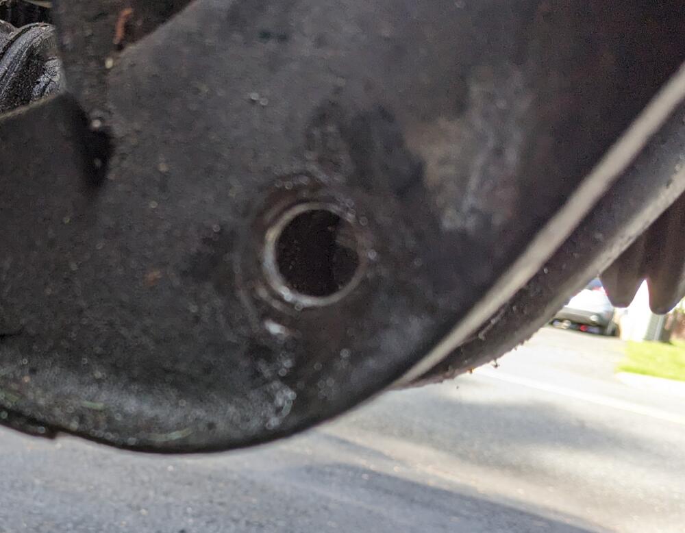
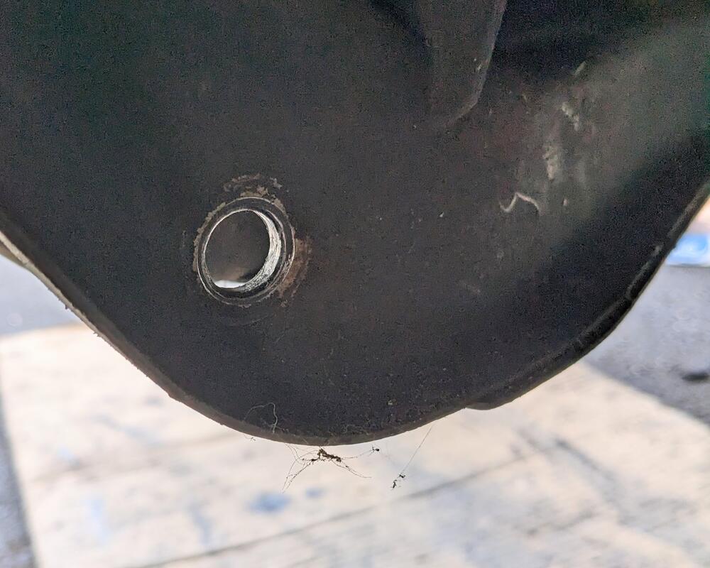
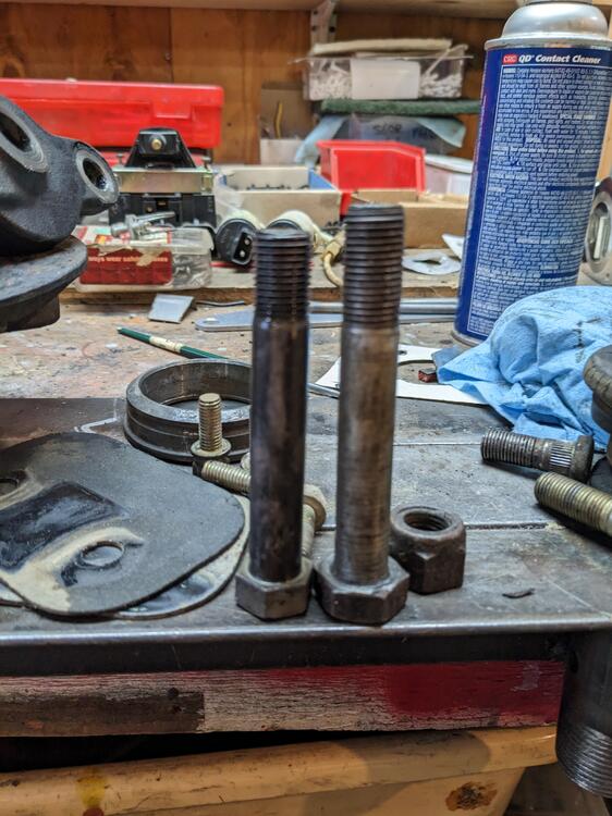
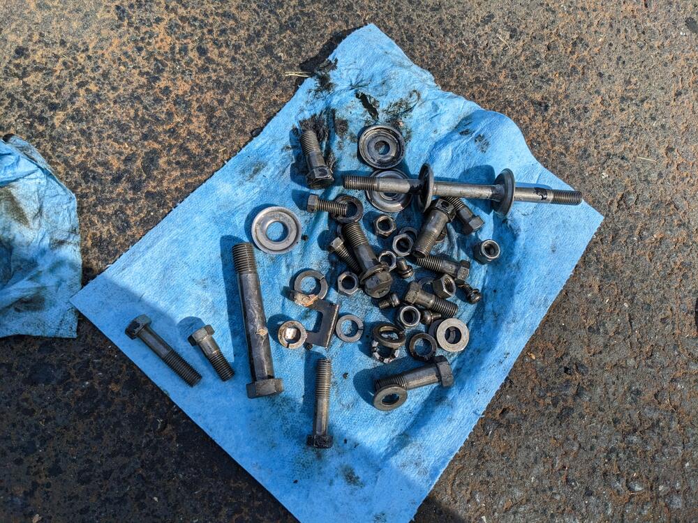
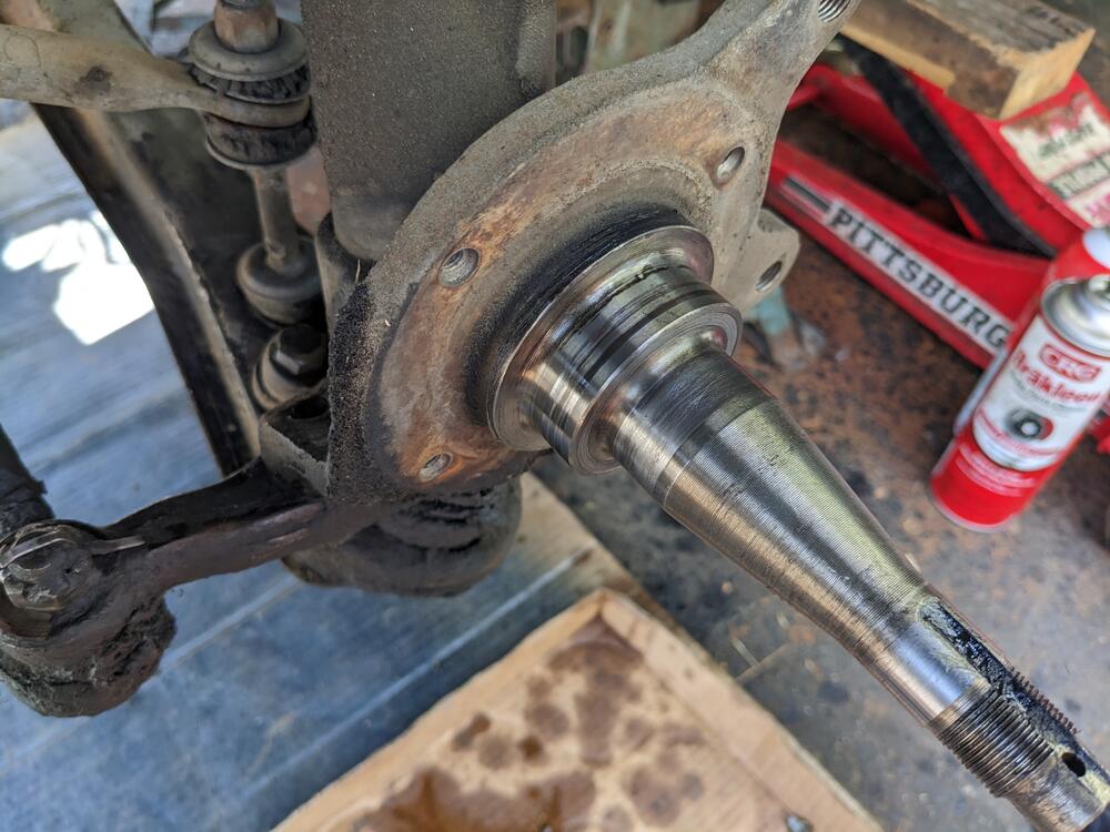
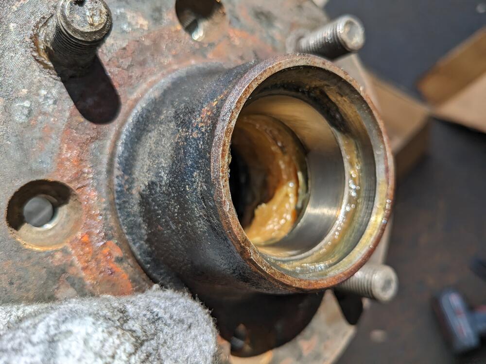
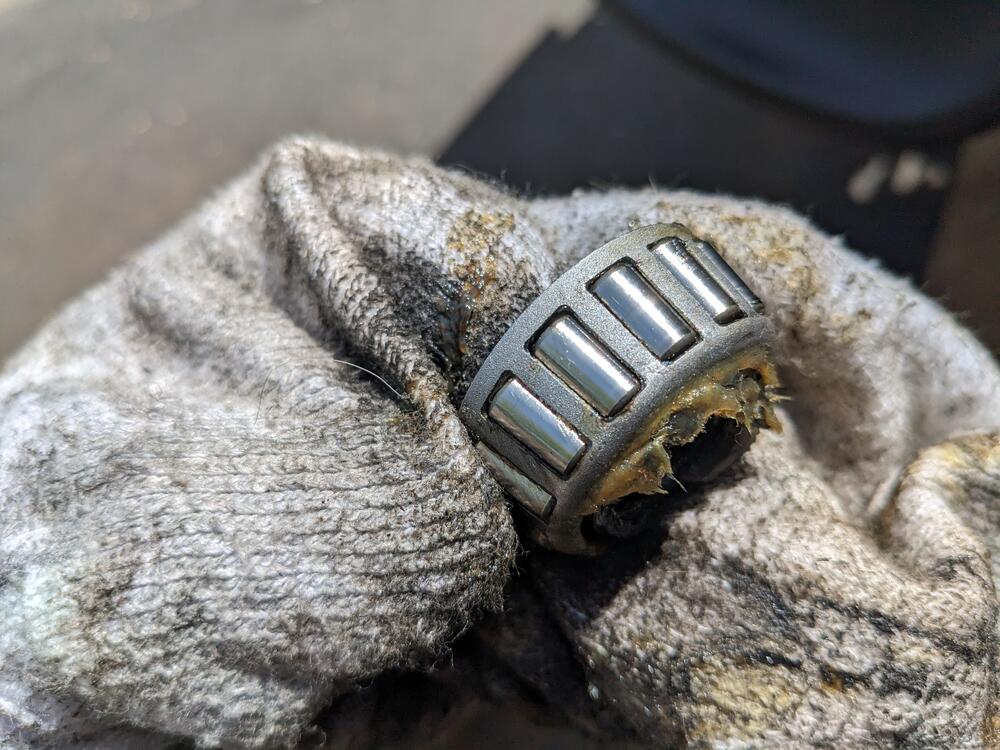
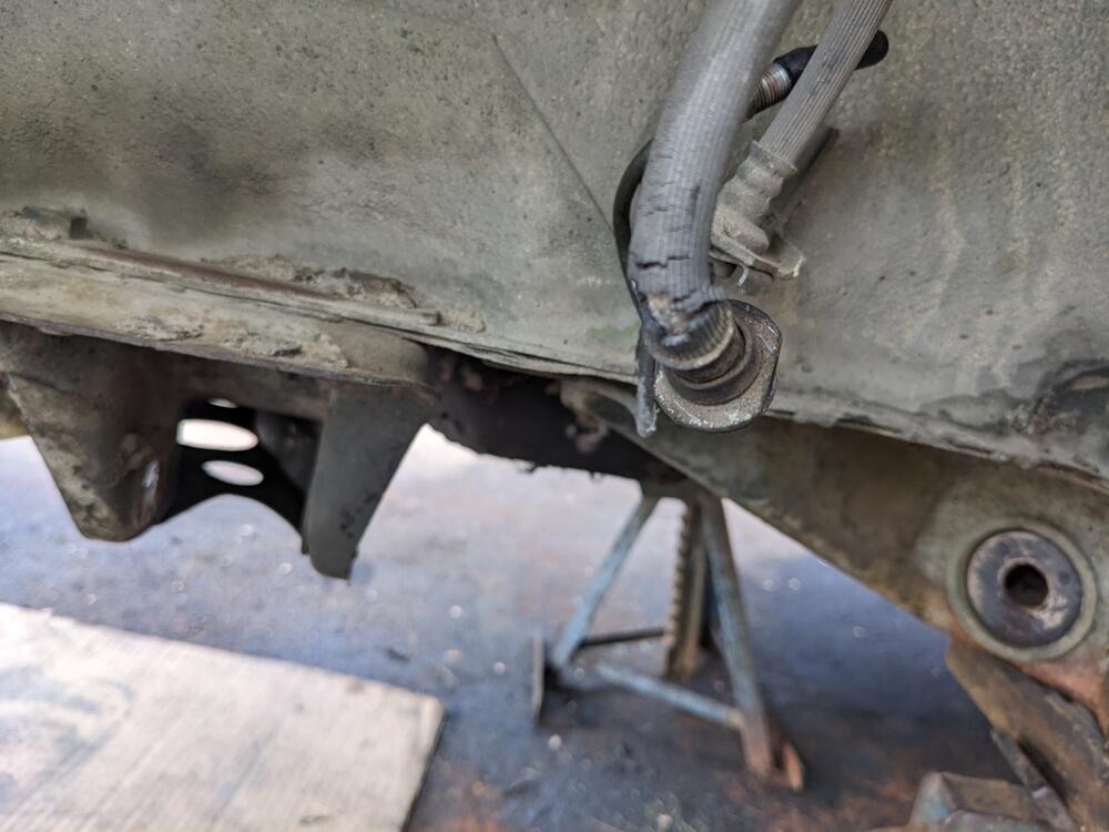
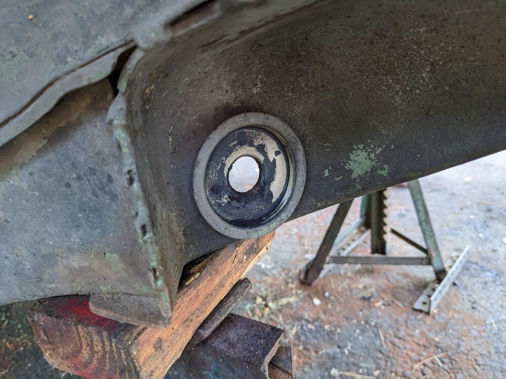
So, I finally got around to stripping the front end. Balljoints fkd, tie rod ends, fkd. Every bushing, fkd. Left side pivot bolt came out clean , no damage to subframe Left side hardware all cleaned up left side spindle. Hub was loose - I was able to turn the nut almost a full flat. The bearings look OK though. So this time around I think I'll just clean & repack them Right side was a bitch. I had to cut the control arm pivot bolt off, it was seized inside the bushing sleeve, and has elongated the holes in the subframe I have a longer M14 bolt (probably off the X1/9, which will work if I have to weld reinforcement washers to the subframe So, the wheels - they will not fit the stock short studs, since they use cone seat nuts that do not recess as deeply as the shoulder lug nuts I removed. Technically, that may be just within safe thread depth for an M12 nut, but I'm not risking that. I didn't see any mention of a stud or lug nut concern when I was searching wheel options. I found the rear studs are longer - so I'll use the 25mm thread depth rears on the front hubs, and get 2" length for the rears Brake hoses are also shot Caster rod seats are good made a start degreasing the back plates, control arms & link arms. Everything was covered in copious amounts of grease from the (lack of) boots of the tie rod & balljoints I'll have to dismantle the struts next. Ho[pefully no nasty surprises with the tubes
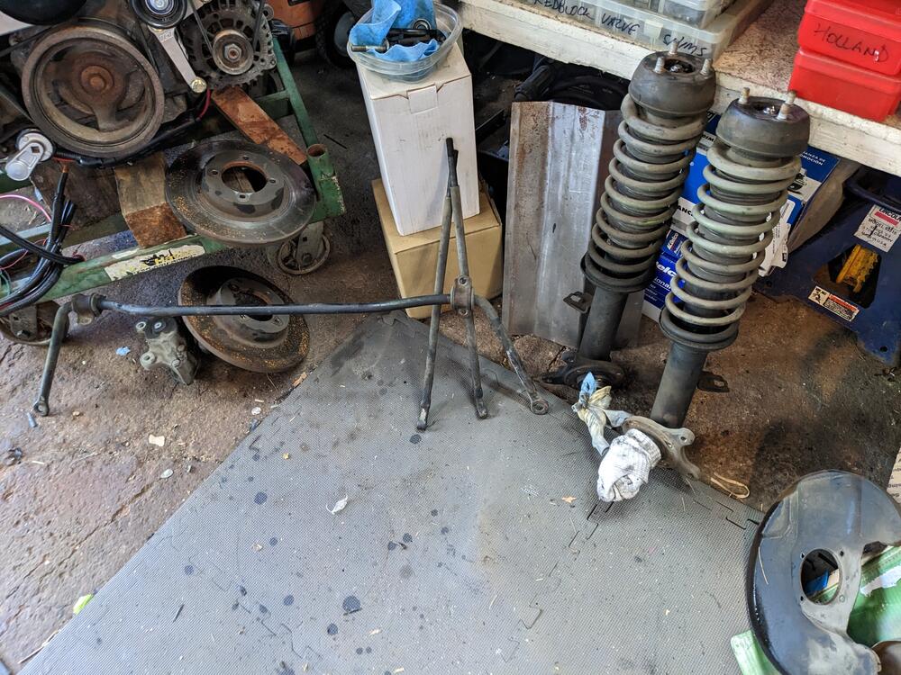
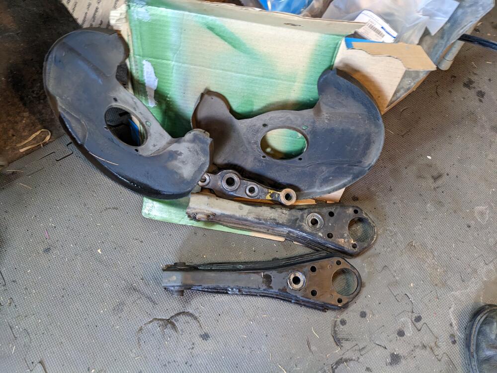
-
Thanks Steve The amplifier relay or the interval relay? #9 or #1 in the relay panel schematic?
-
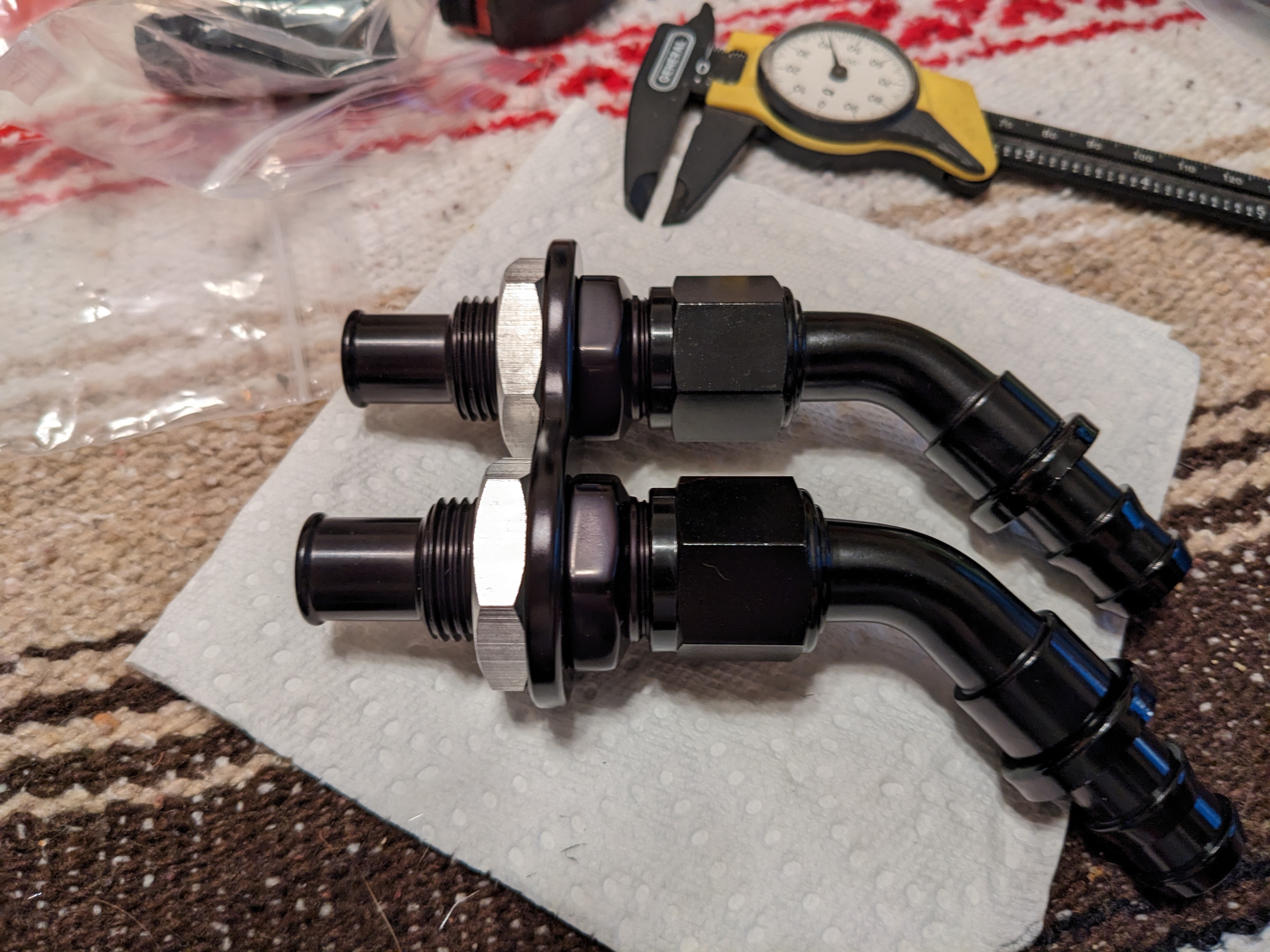
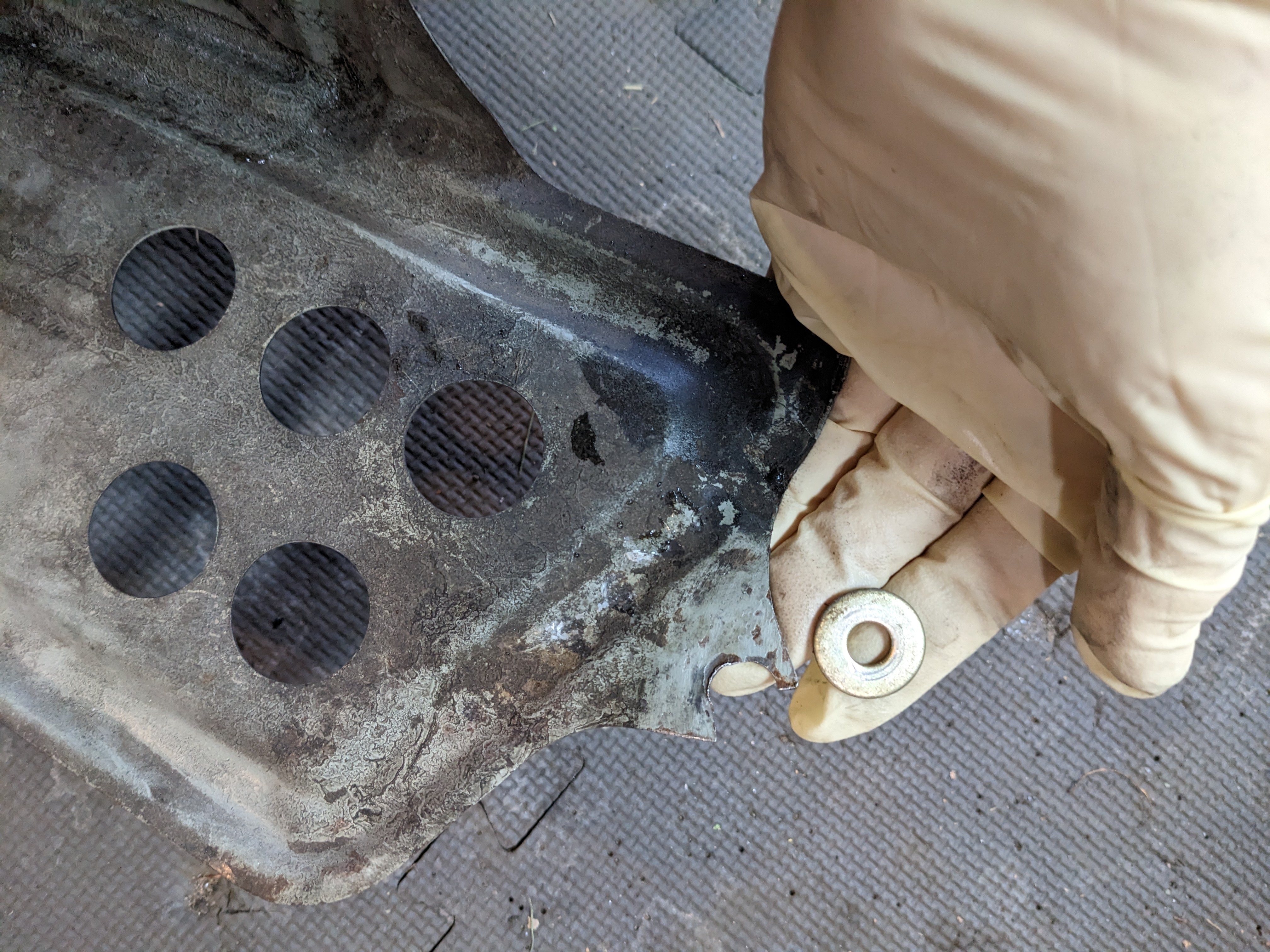
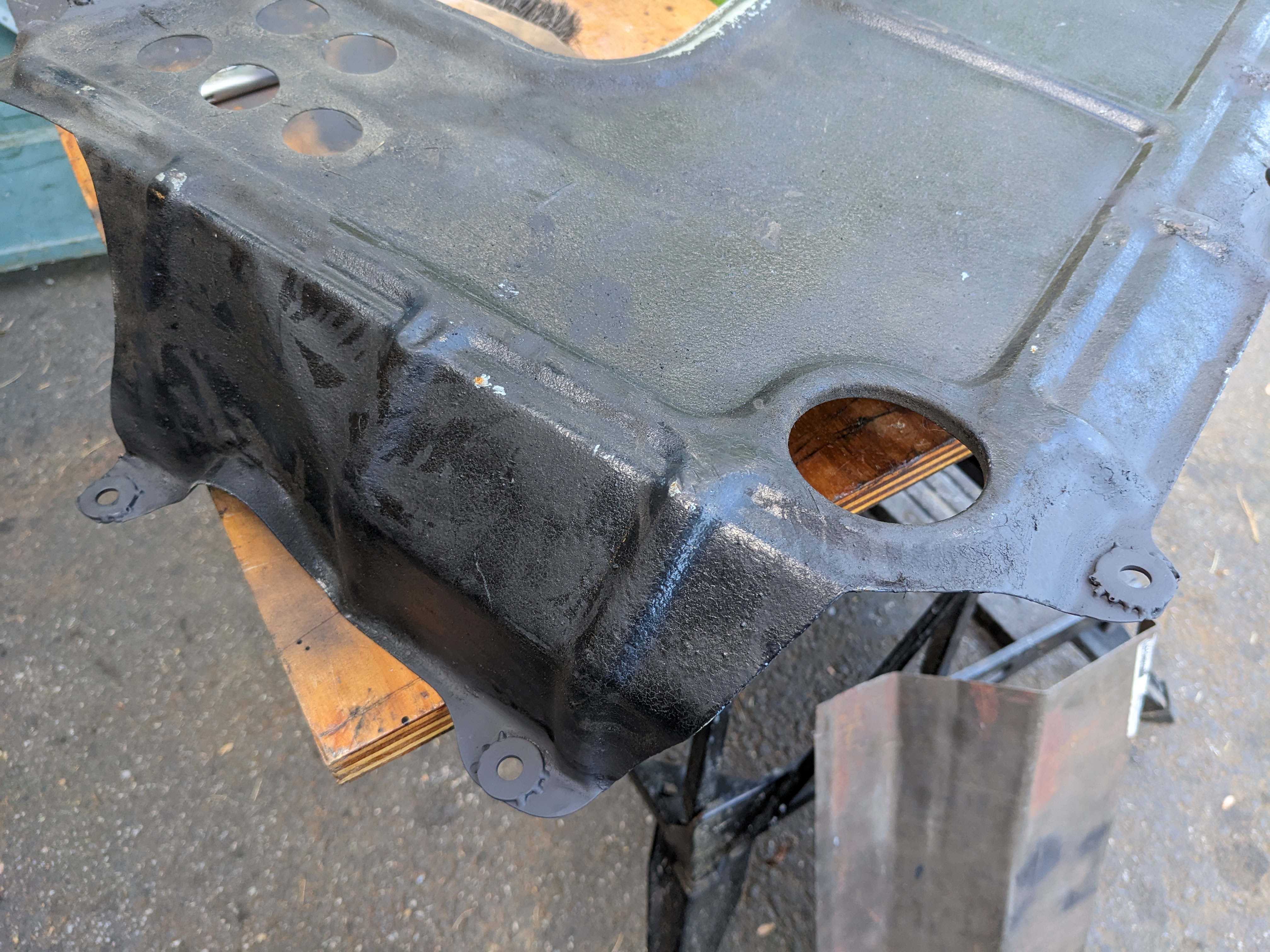
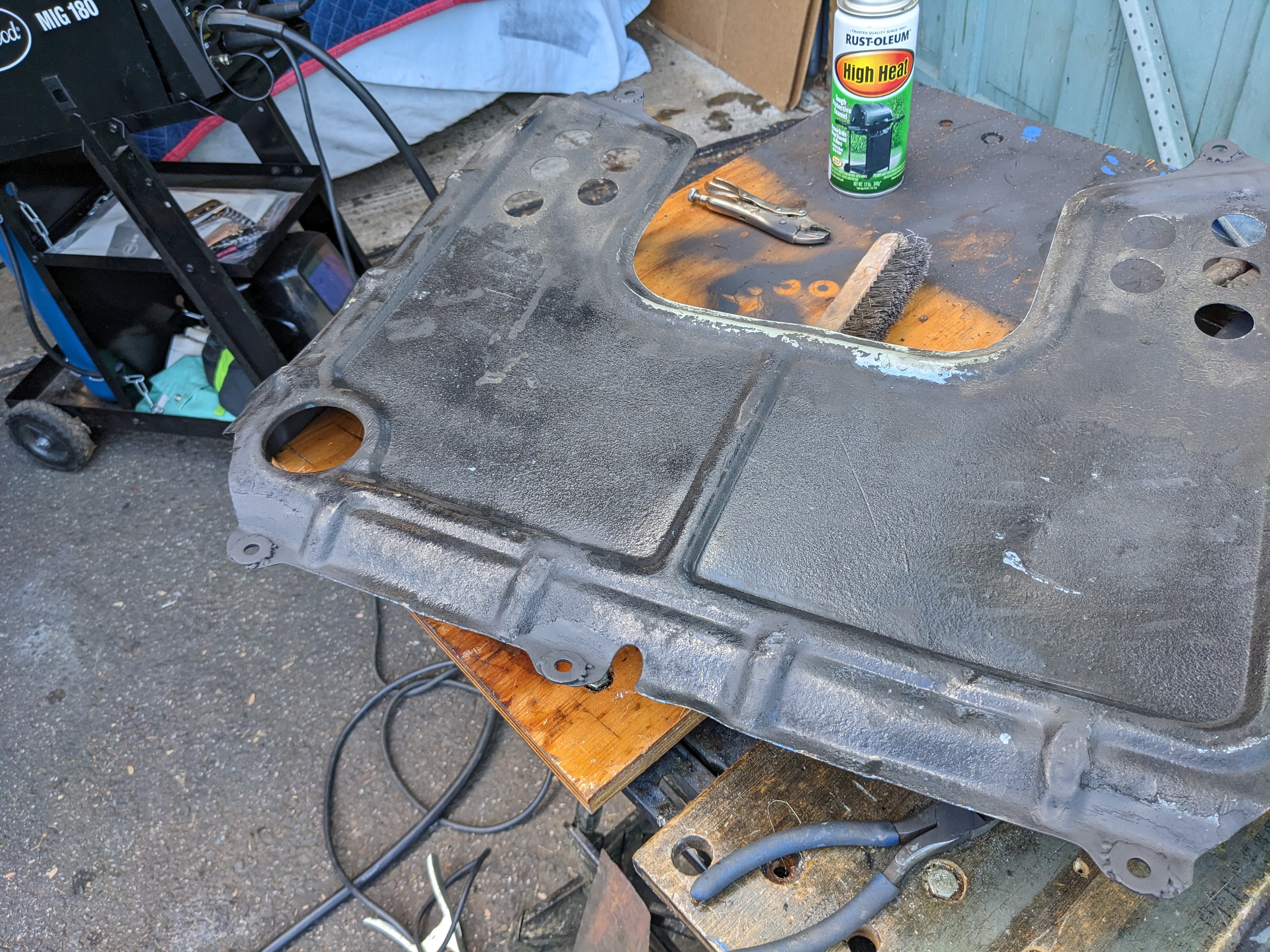
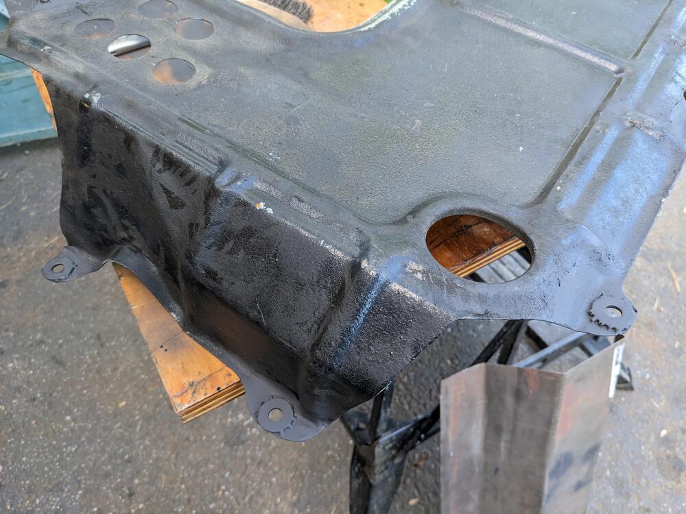
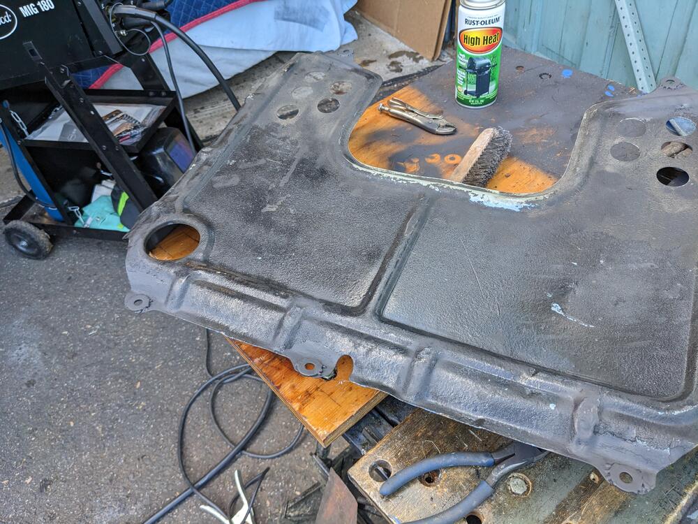
5/8 Stainless pipe for the heat pipe along the block, & bead roller tool arrived, along with the bulkhead fitting I'm going to use 5/8" hose barb to 10AN bay side fittings As an aside, I had to remove the belly pan to do this work, and decided to repair the torn ear & reinforce the other 8
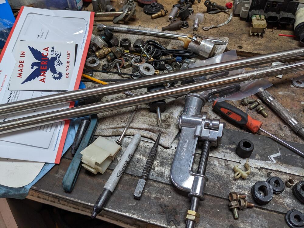
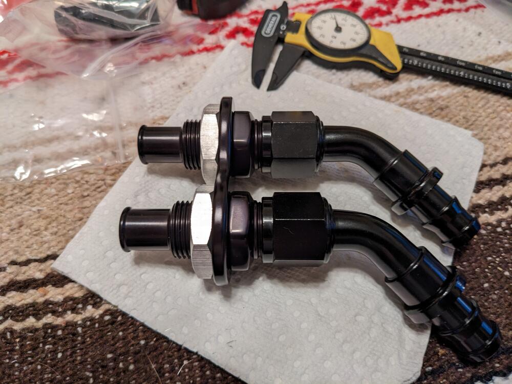

-
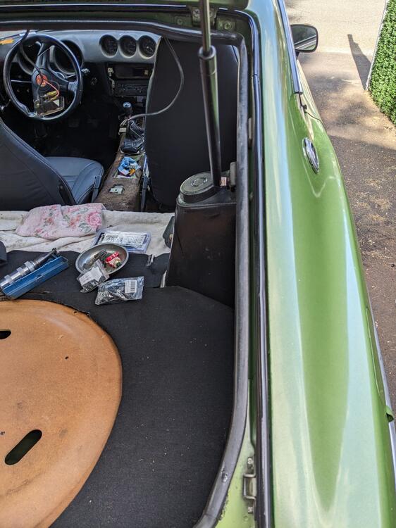
Actually it's easier than that - I heated the shafts until lightly glowing red , then dunk in used engine oil bath & leave them until completely cool. Makes a hell of a smoke cloud. New upper bulb seal arrived (@jfa.series1) , so I finished up the hatch outer drip rail sealing. I used a short section of washer fluid hose to join the bulbs
-
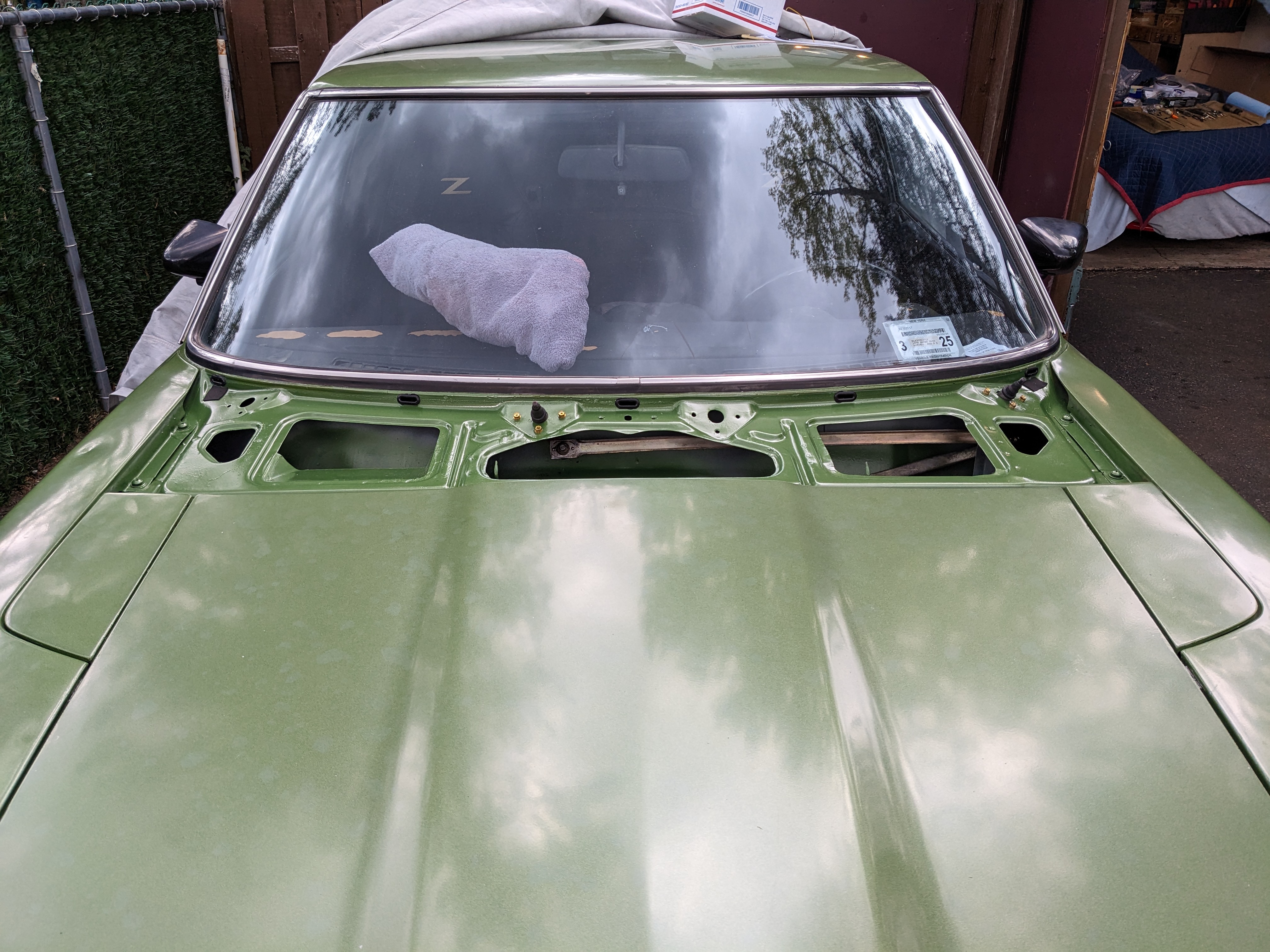
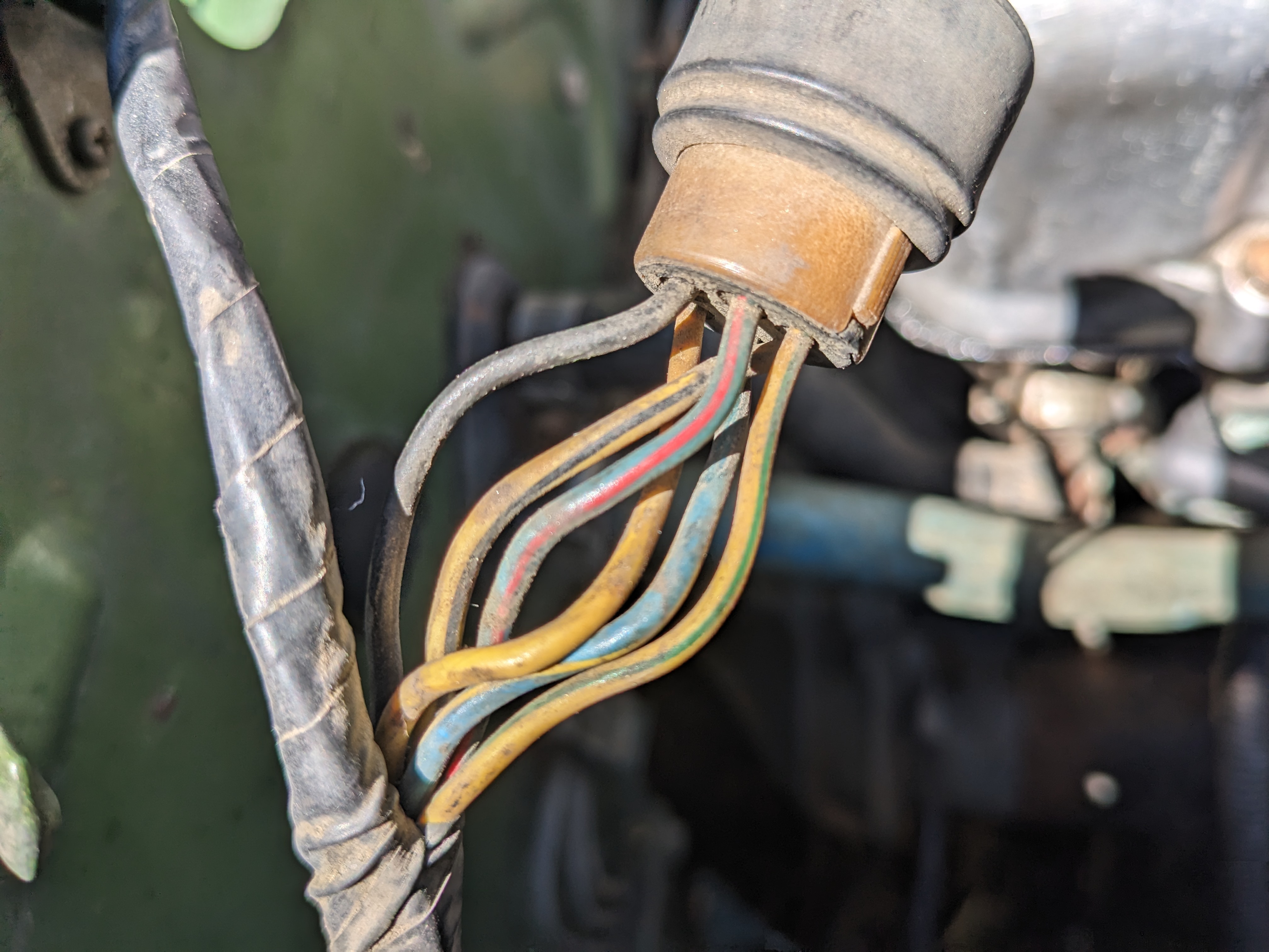
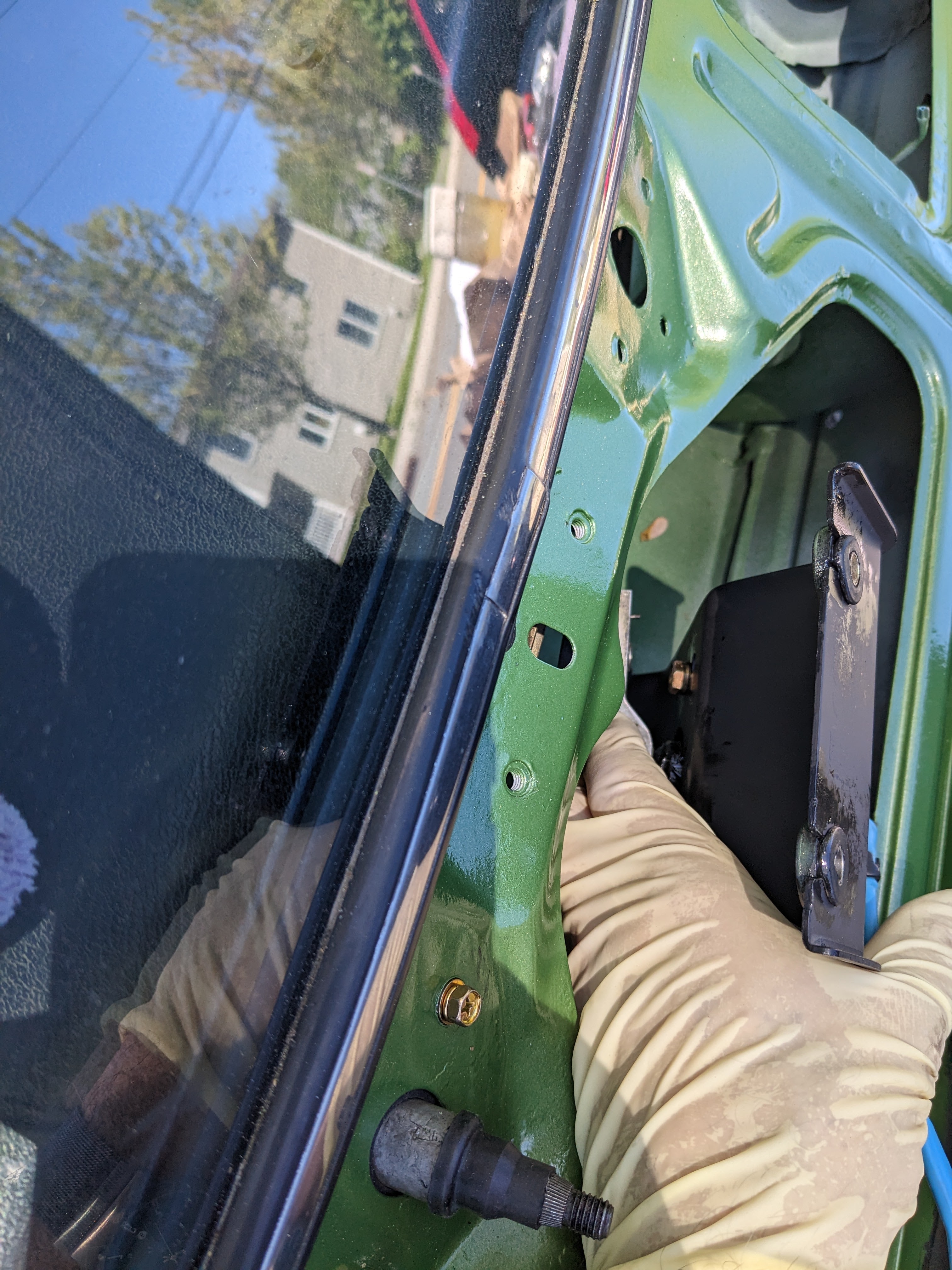
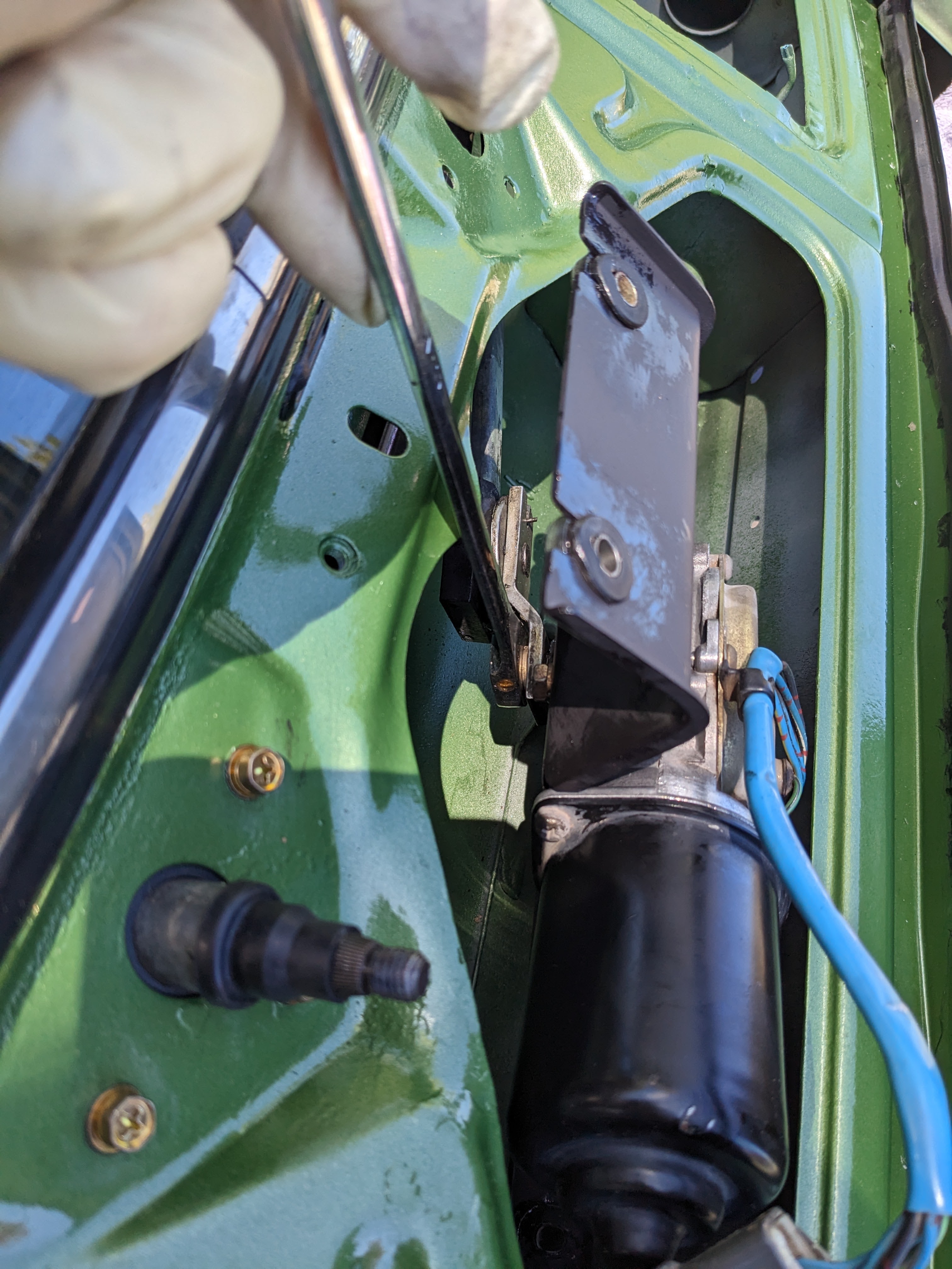
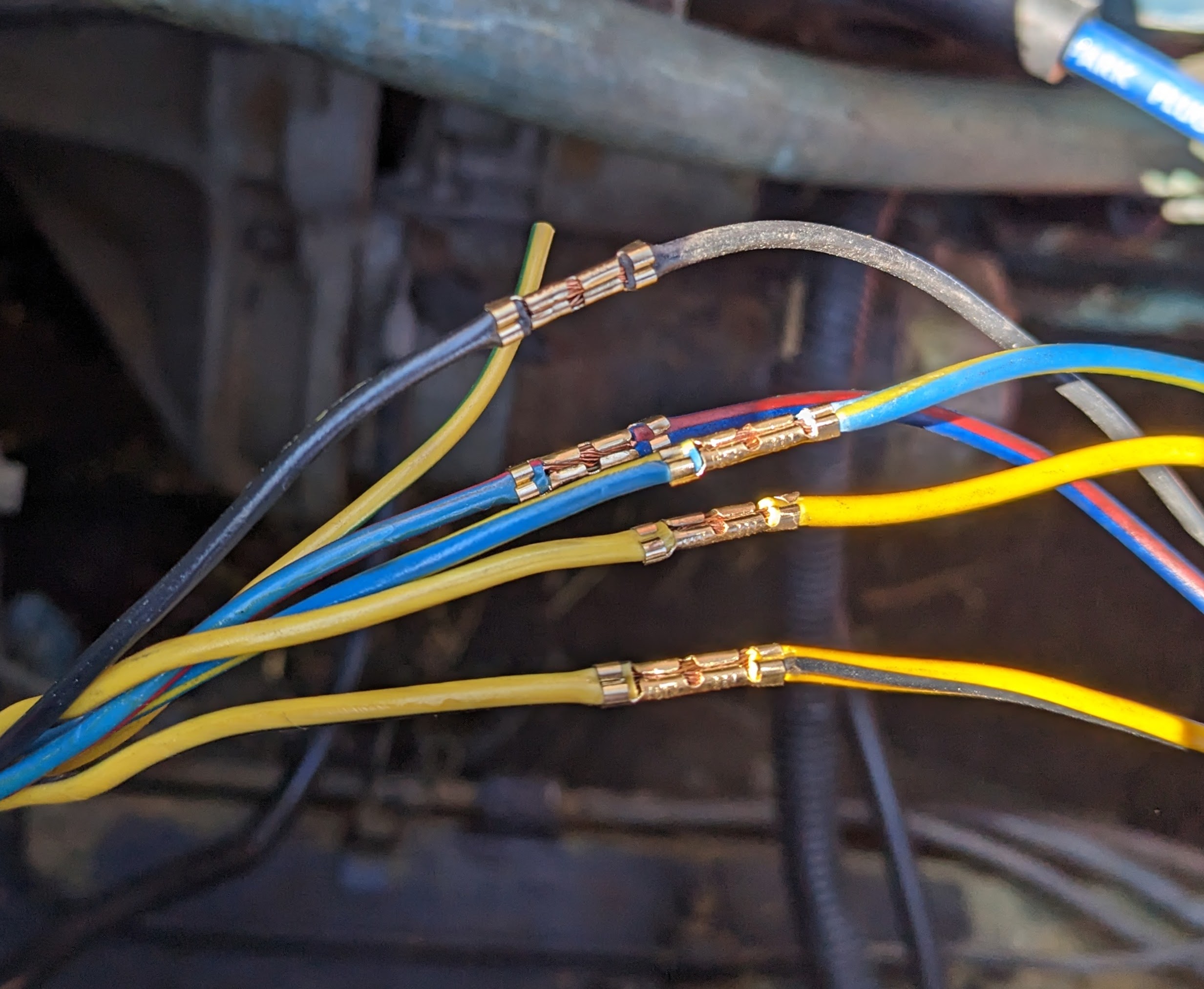
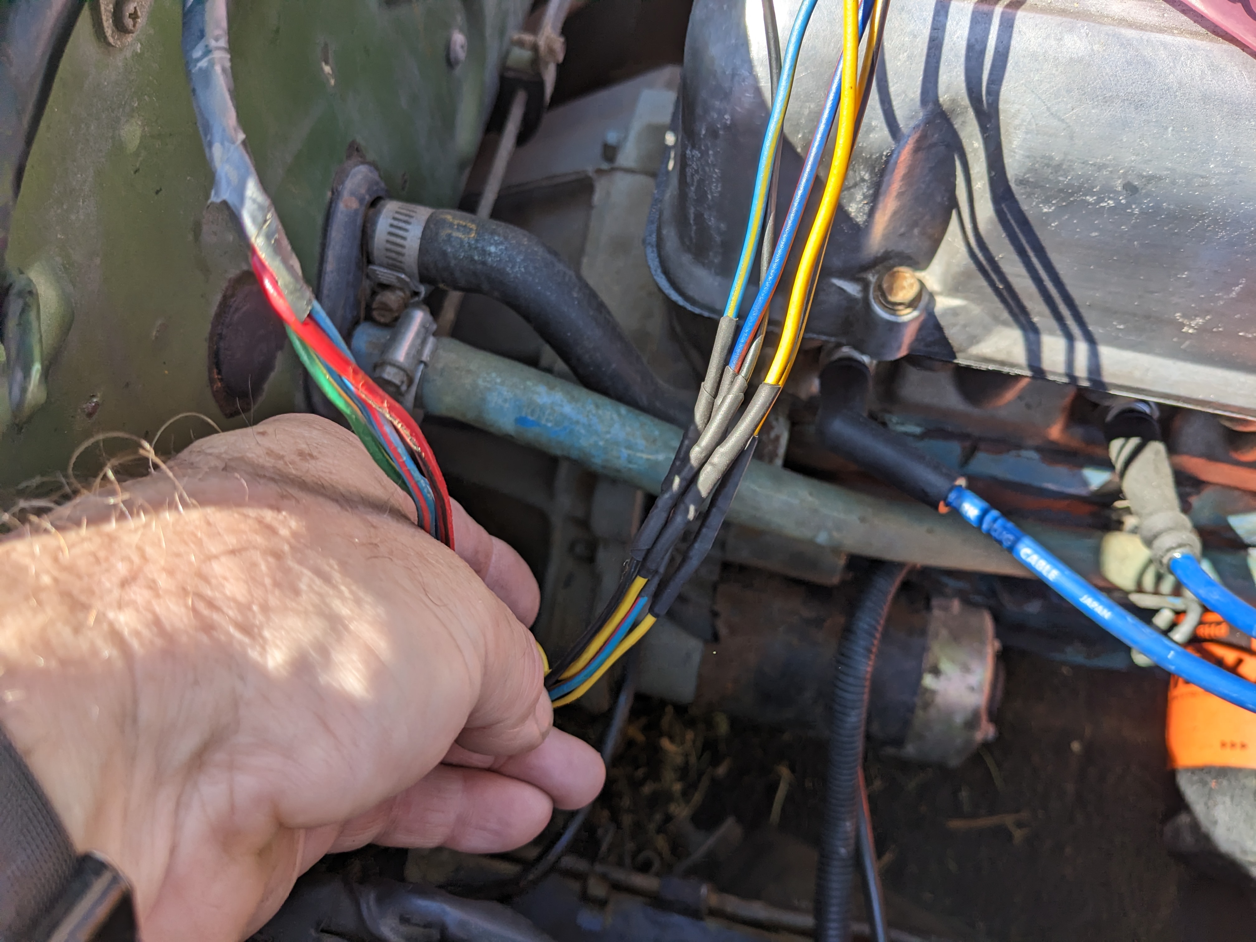
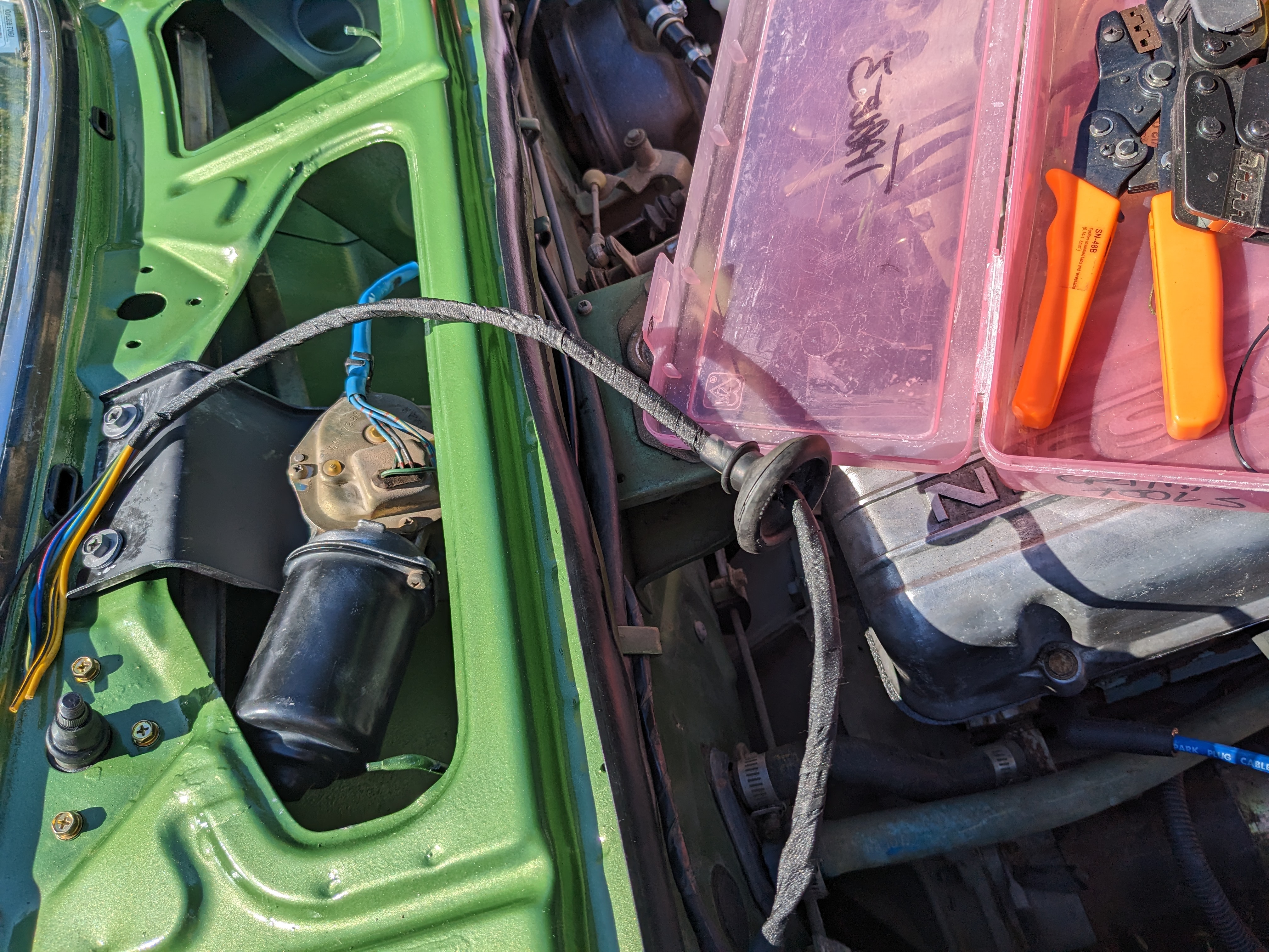
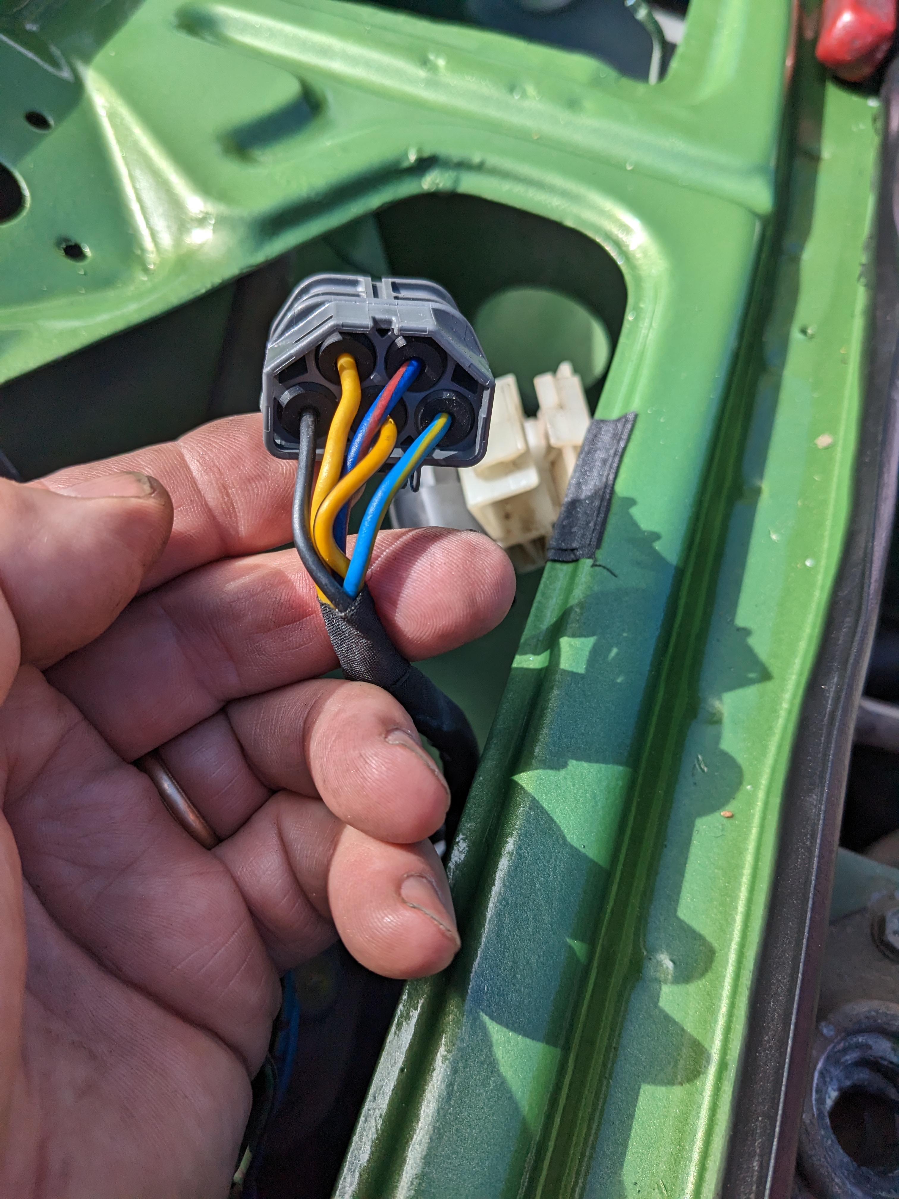
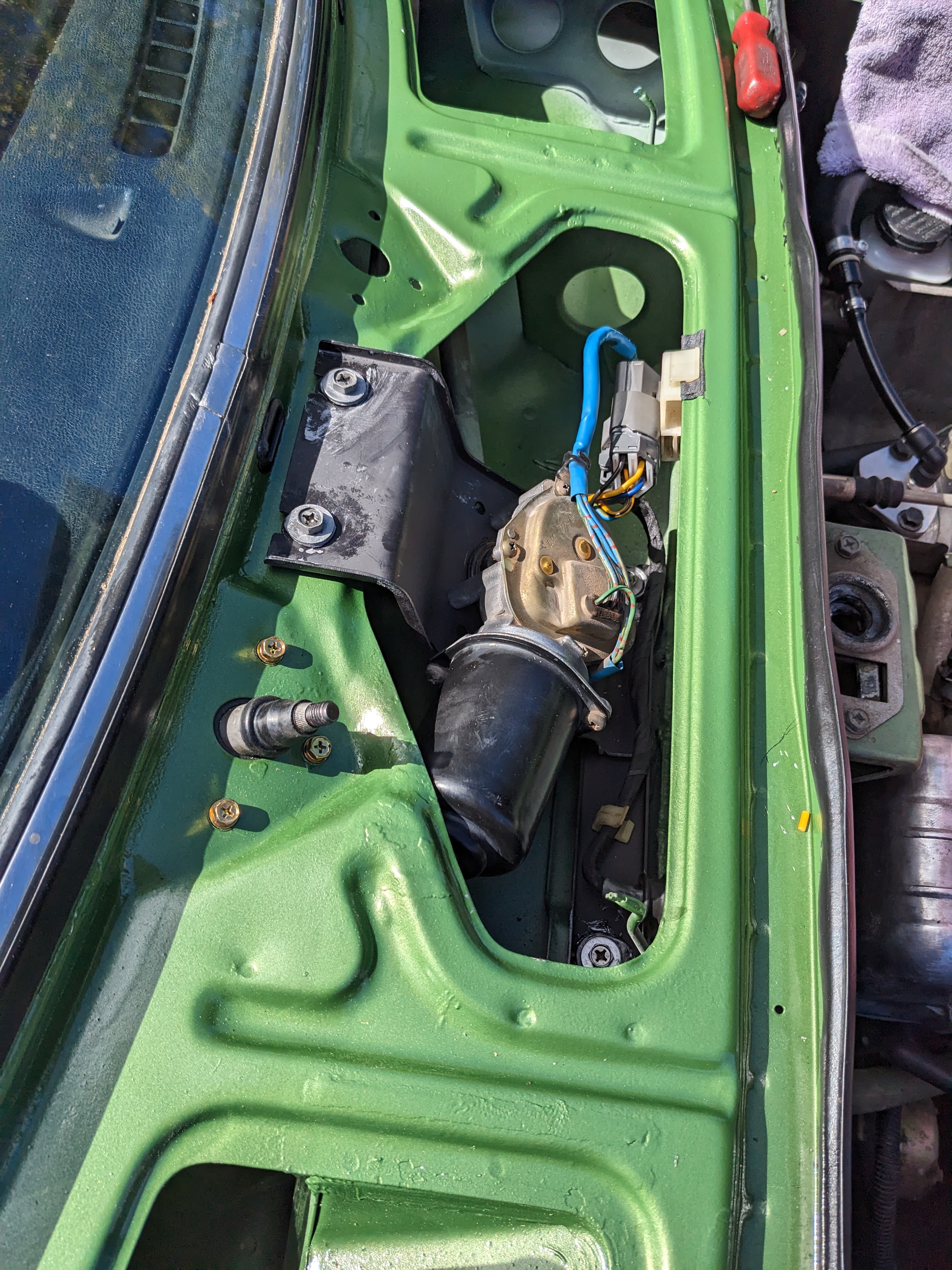
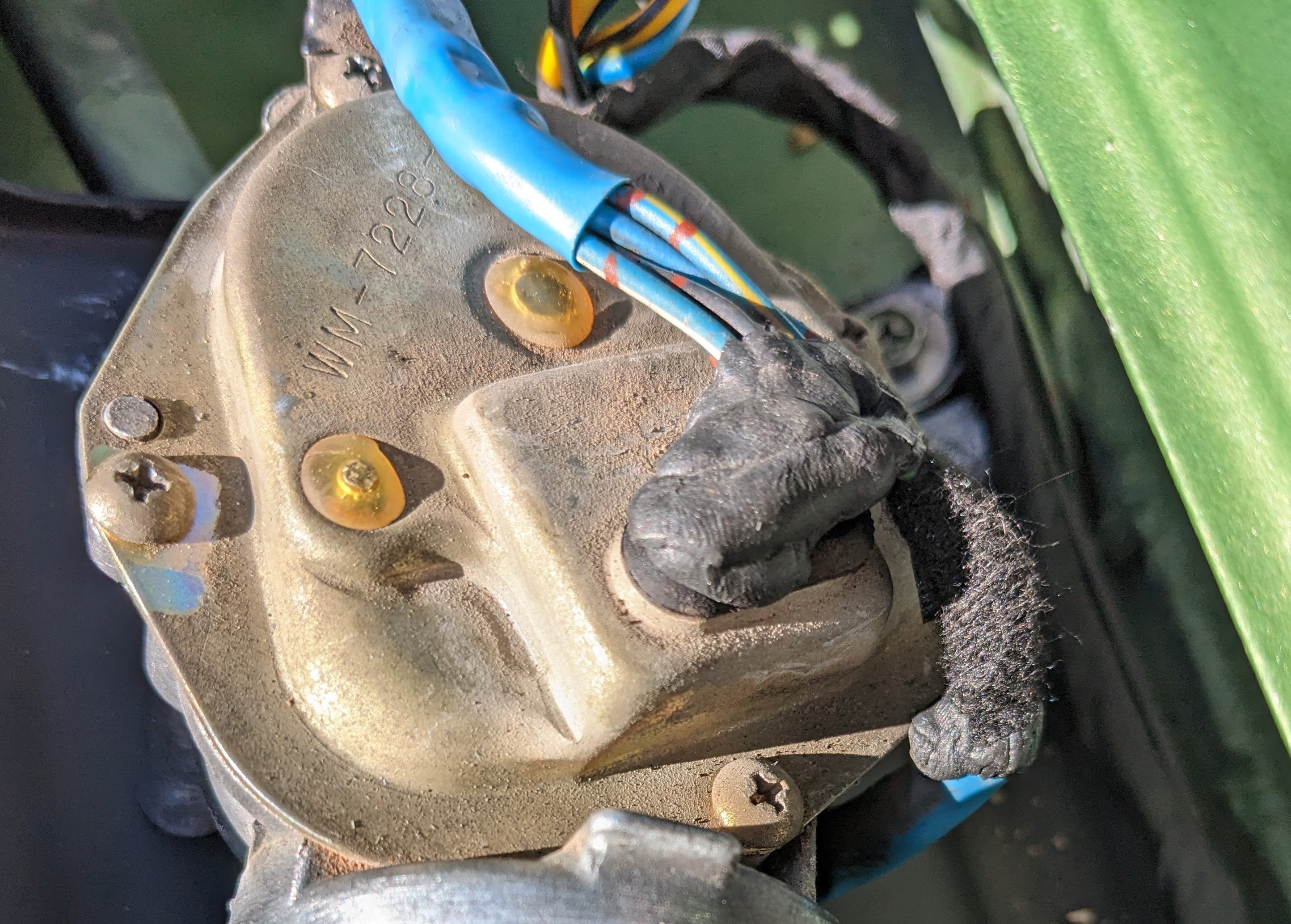
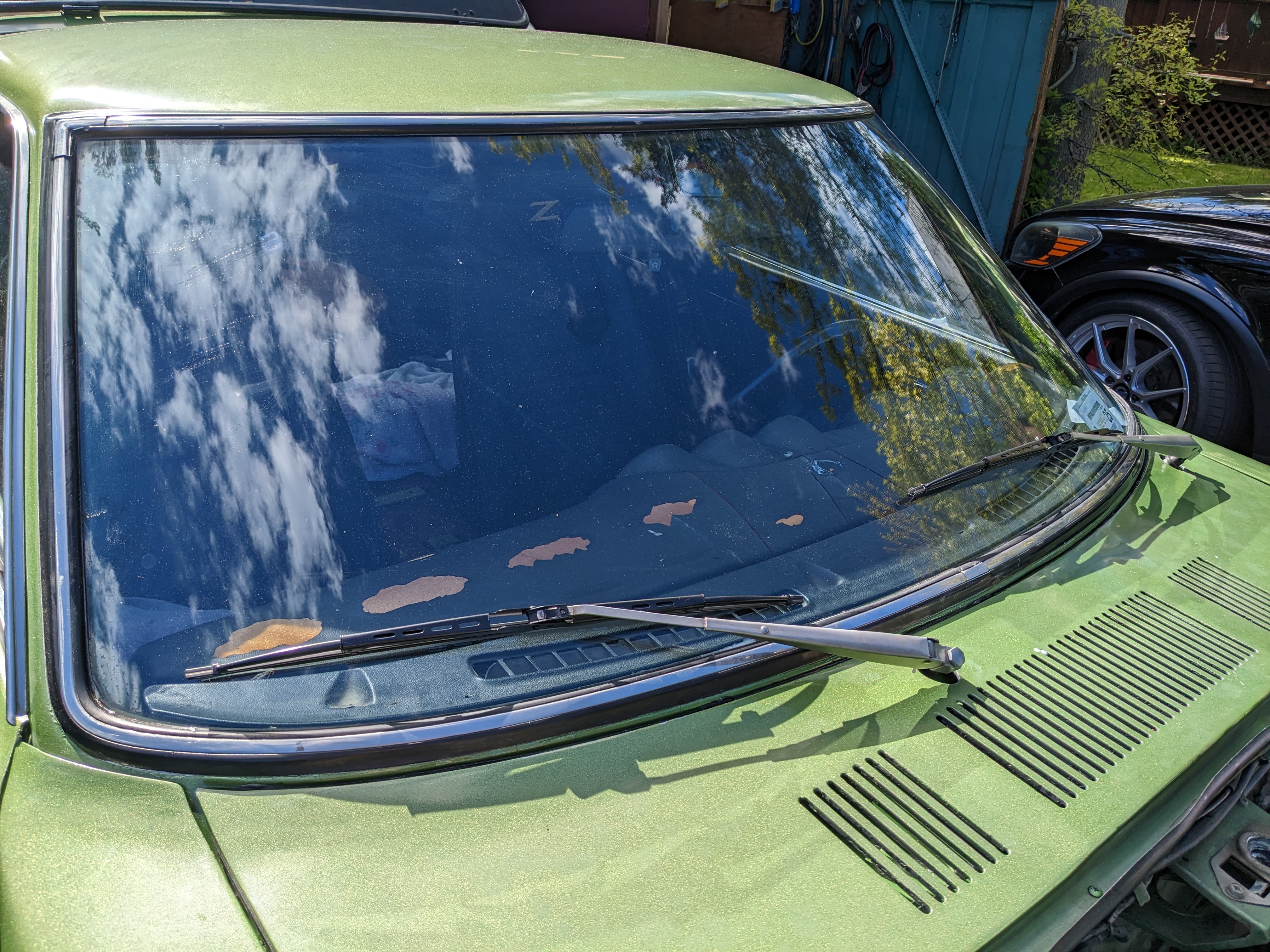
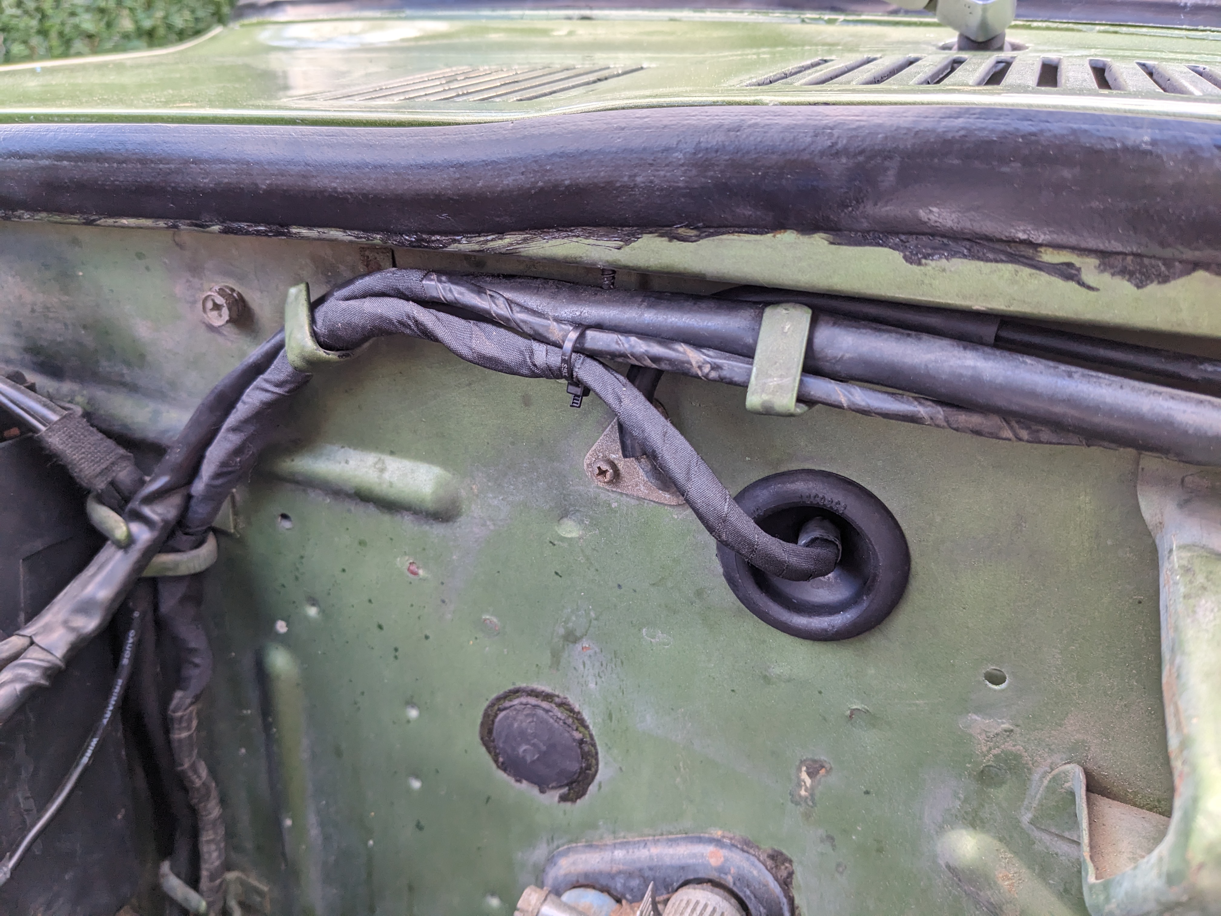
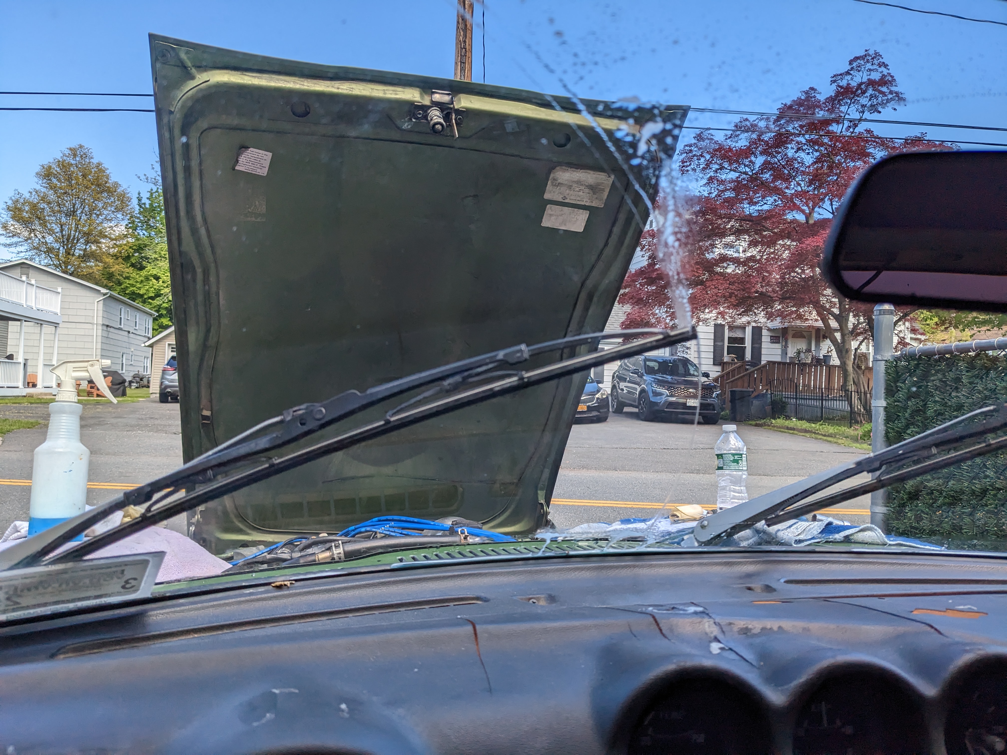
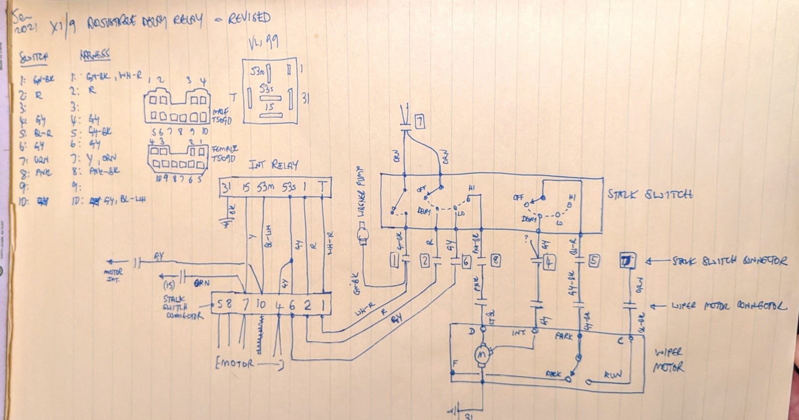
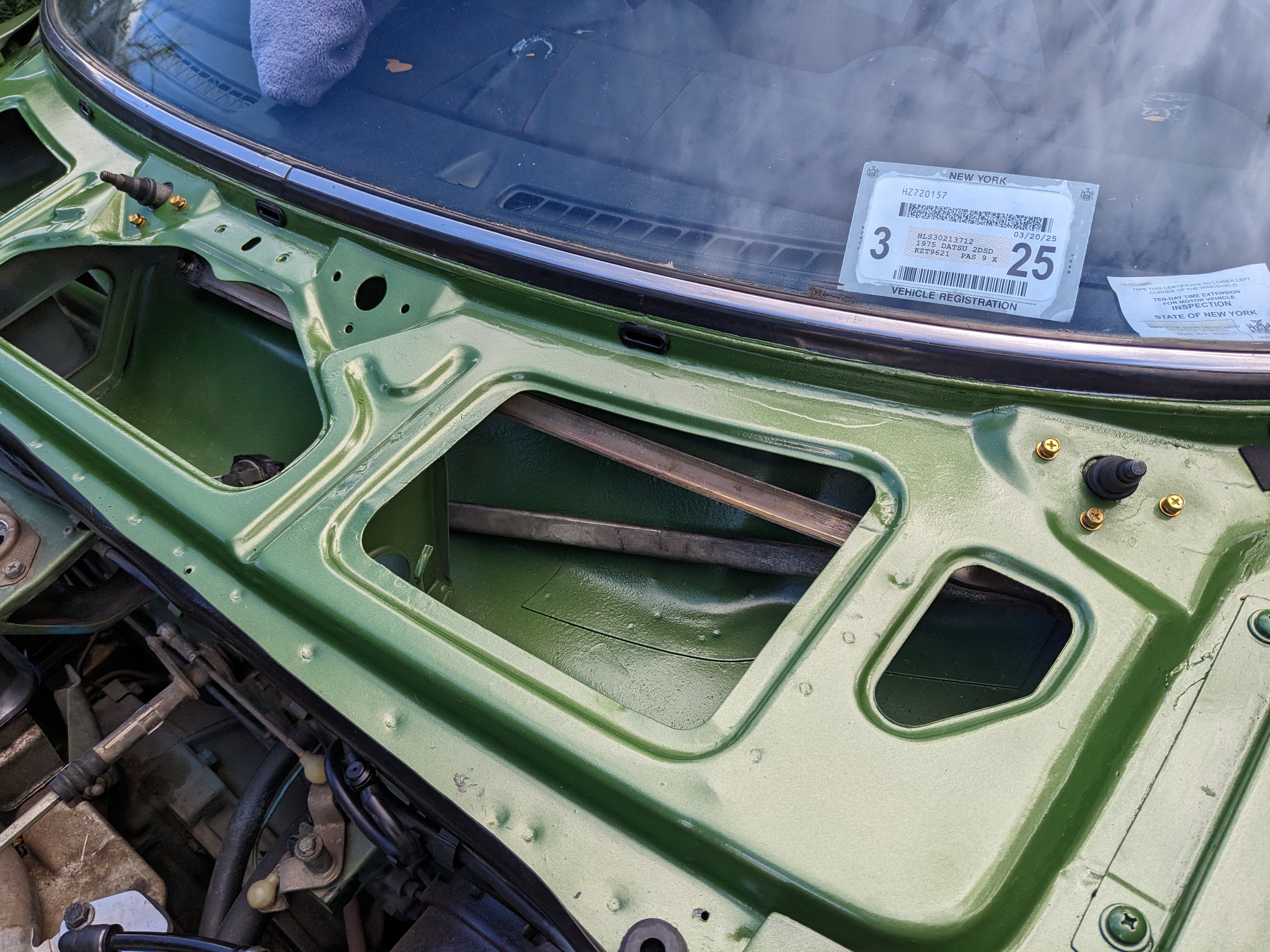
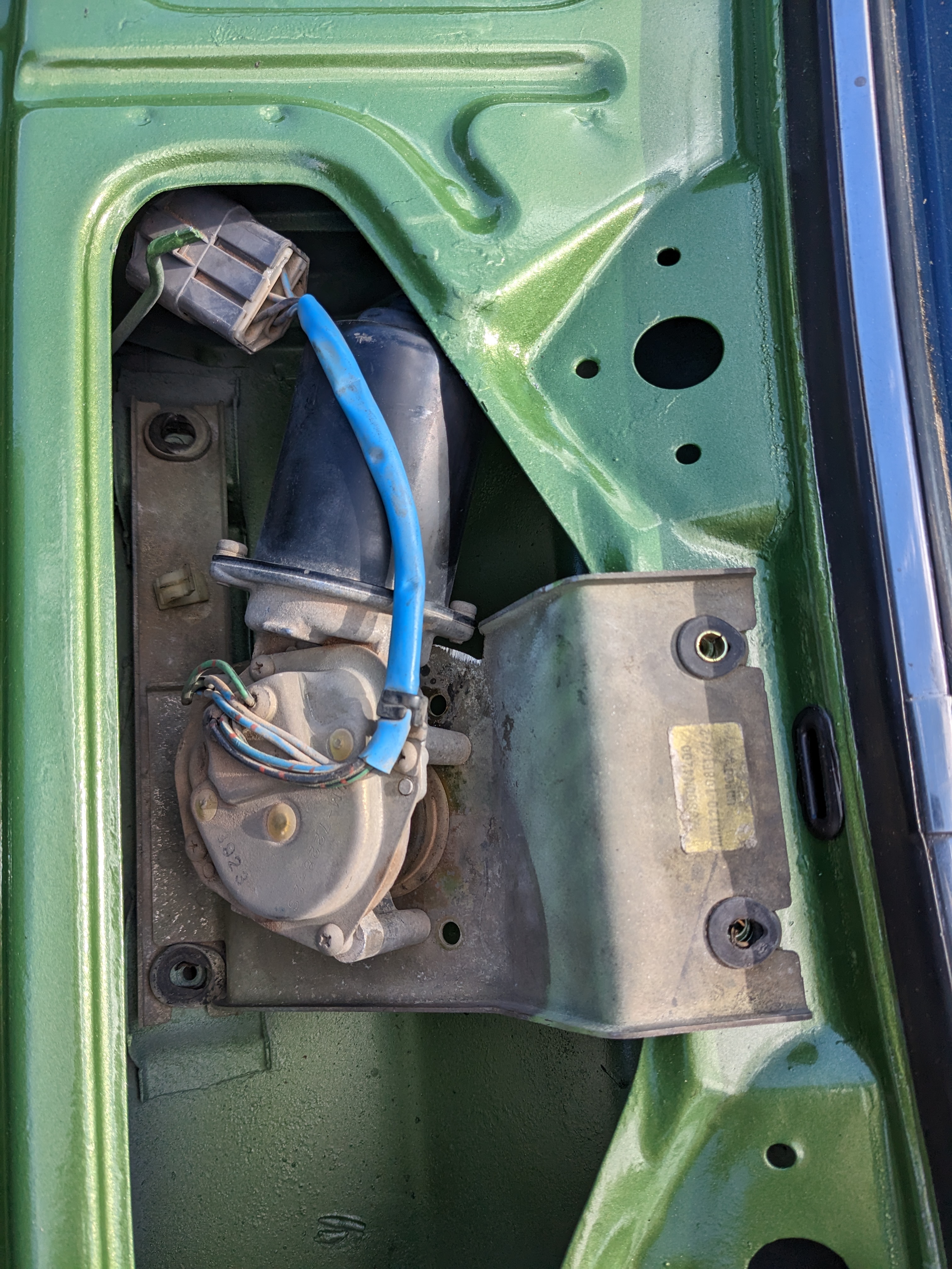
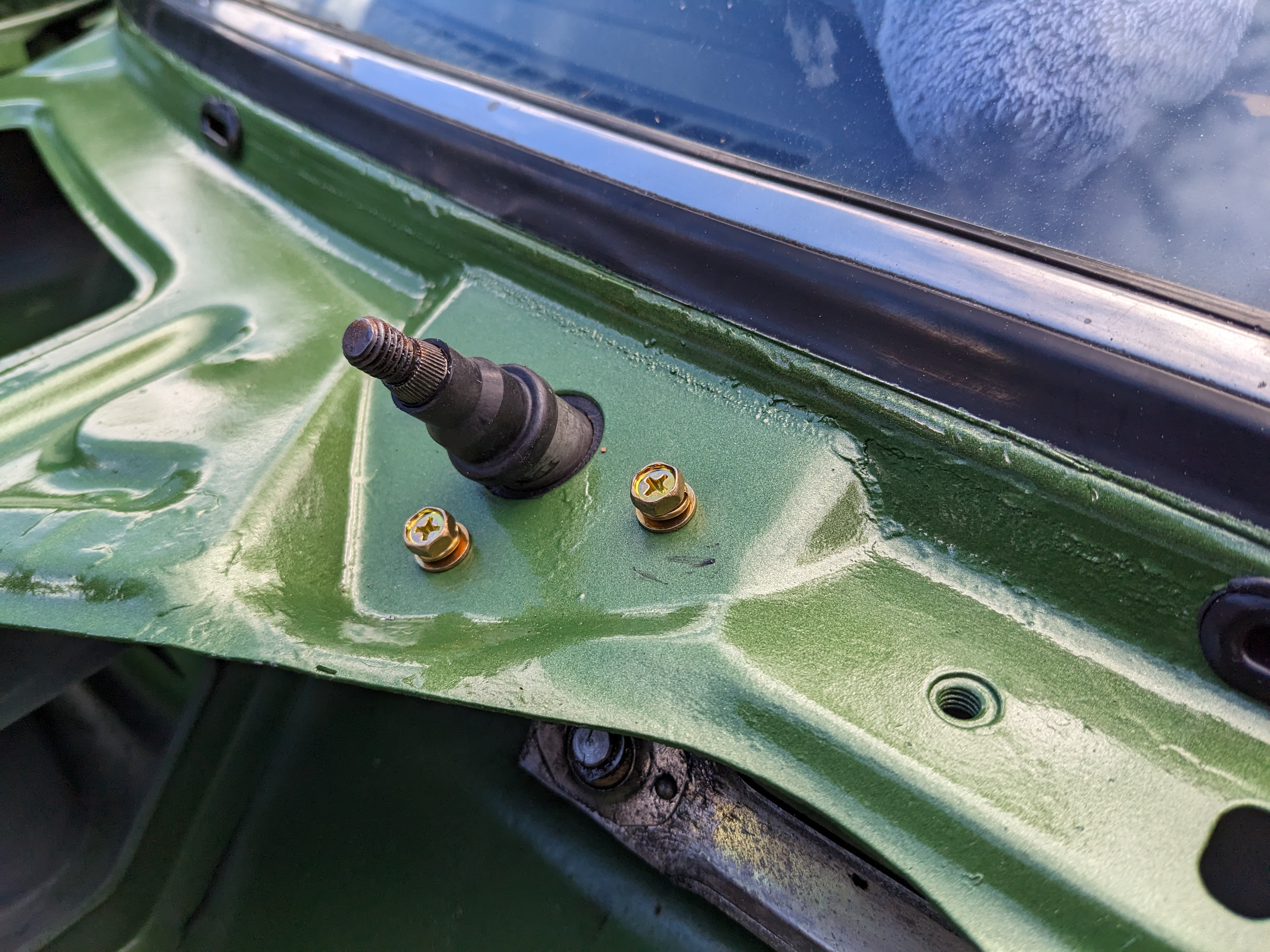
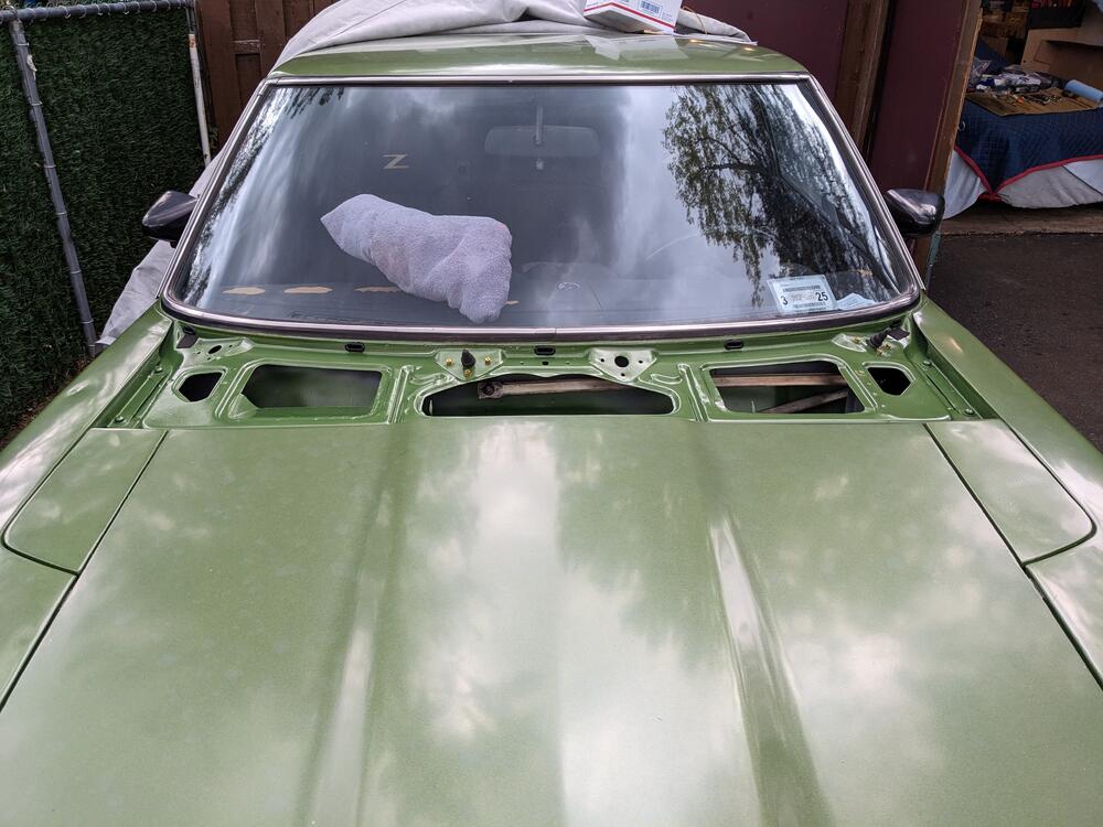
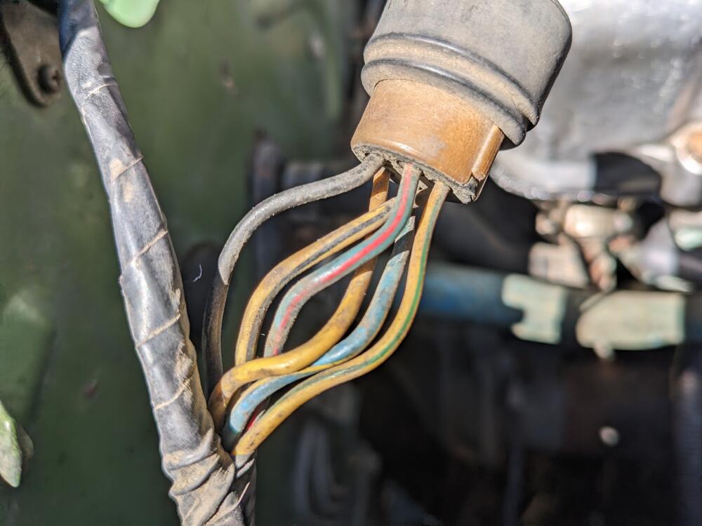
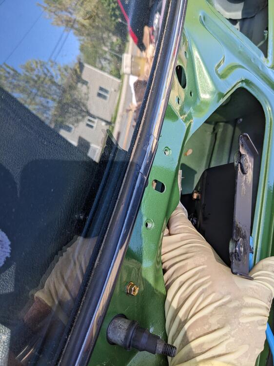
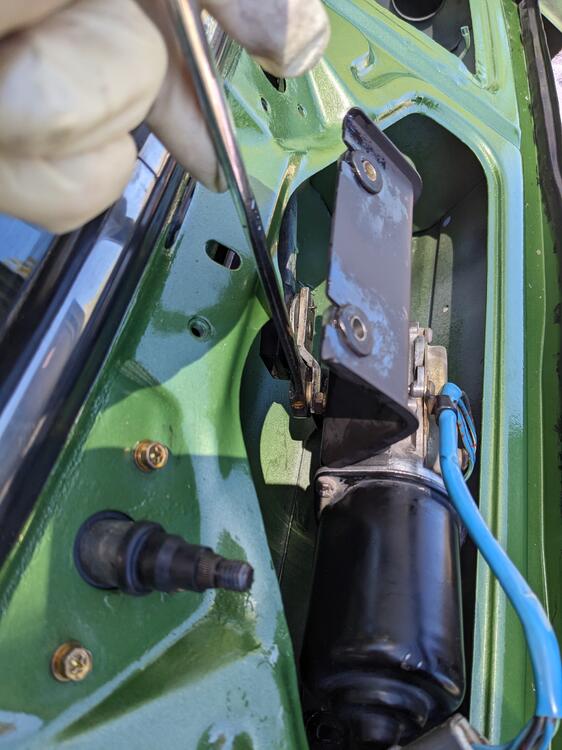
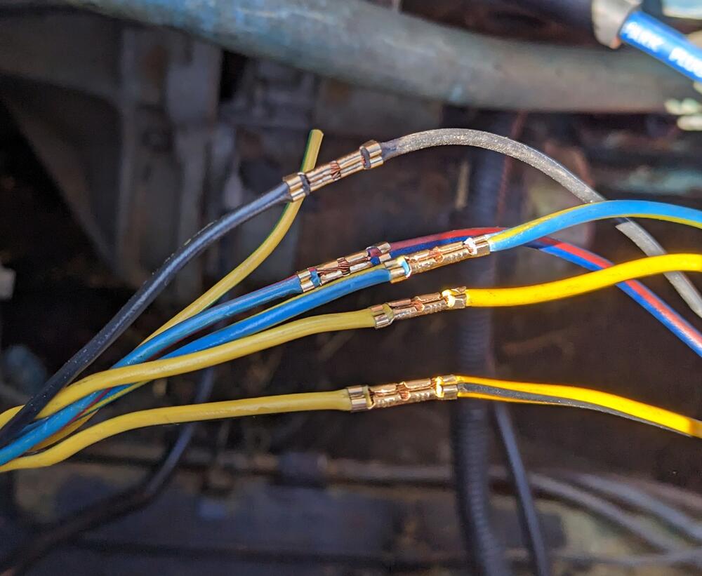
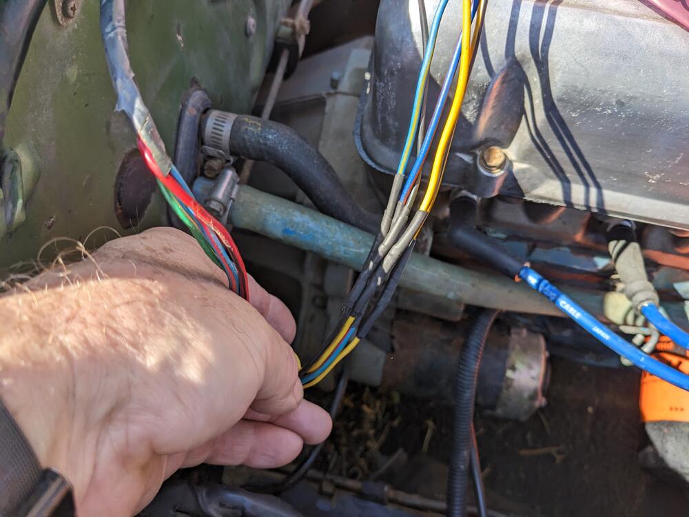
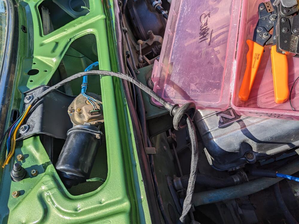
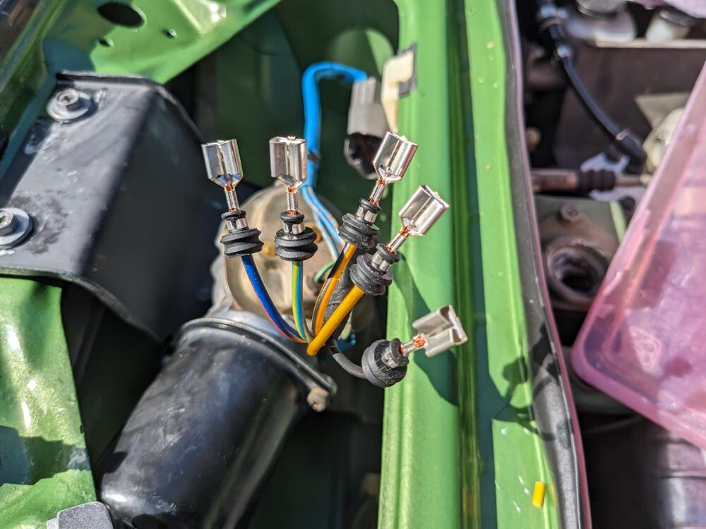
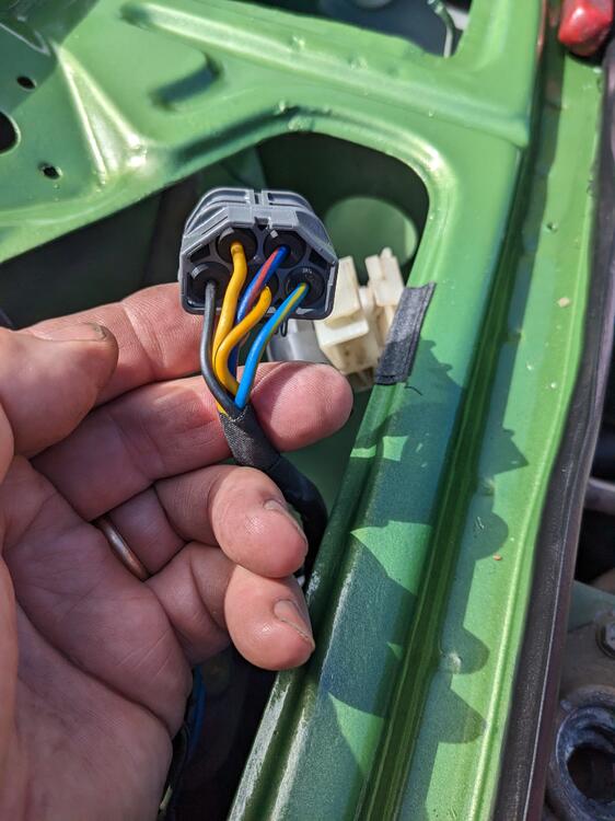
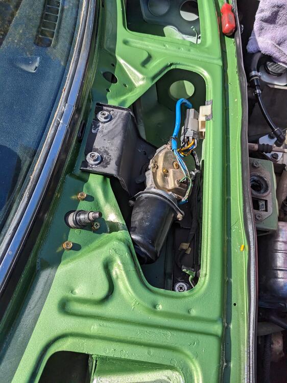
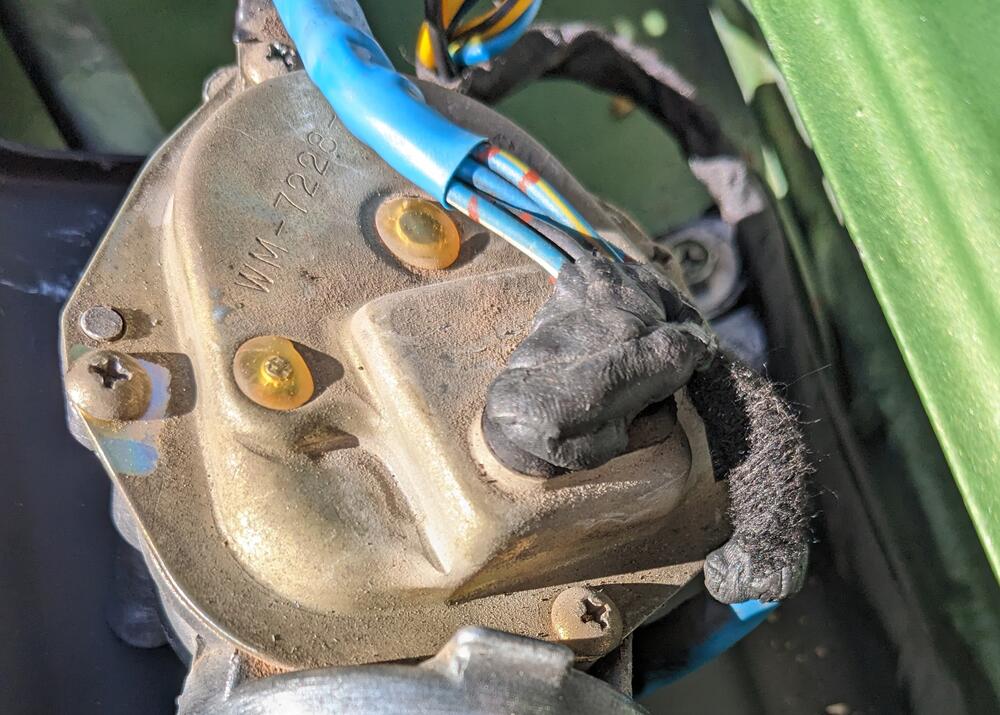
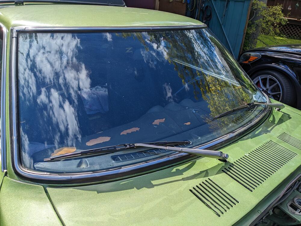
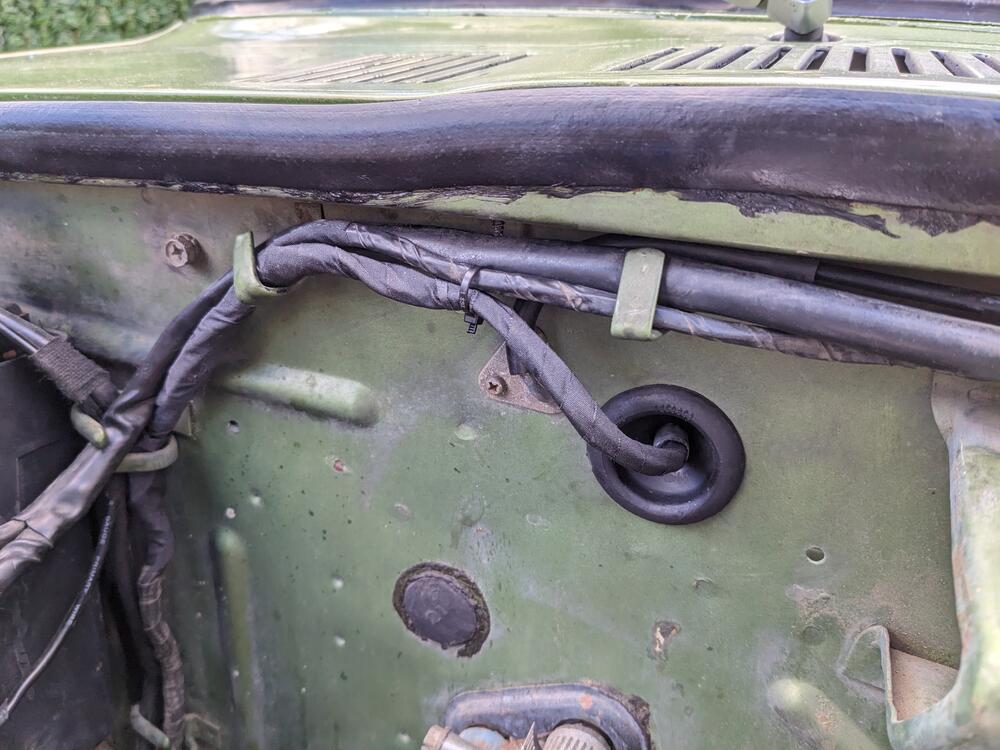
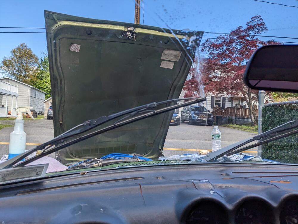
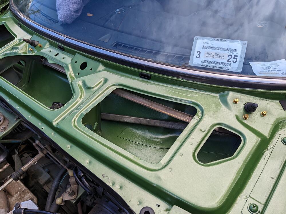
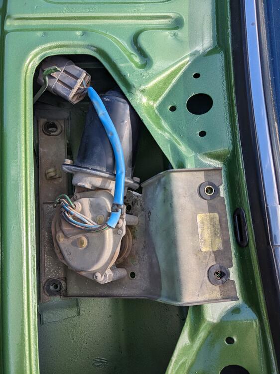
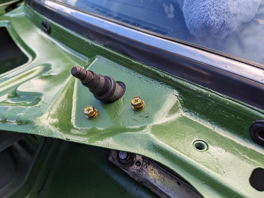
Got the bracket & motor back in the cowl, and rewired for the Honda Motor. I found that one hand can be fit behind the bracket from the right side to get the linkage arm nut back on the wiper motor. I decided to cut off the Datsun connector as those small pins just seem iffy for the load of the wiper motor, given their antiquity. I added lengths of same color wire to extend the stock harness through the cowl, used a Volvo firewall grommet, and then added the Honda (Yazaki 58XS) connector and female pins. BLK, BLU-R, Y,Y-BLK, BLU-Y. Y-G is unused. Solder joints are a bad idea - so I bought a large number of crimp splices some time back. Color-keyed wiring came from my old 80's X1/9 parts car. I removed the entire dash harness before junking it. double shrink wrapped I noticed that there is extra weather-strip glue under the seal - I'll have to get that off I attached the wires without the harness first, to just check the mapping from Datsun to Honda indicated in the earlier post The wipers worked as they should - interval, low and high, parks as it should, so I put the wires into the connector Moved harness routing over to the left & clipped it to the cowl lip Put some butyl over the harness feed throughs, since I don't have the plastic sheath for the whole affair arms & new 18" blades installed checked the washer nozzle adjustment
-
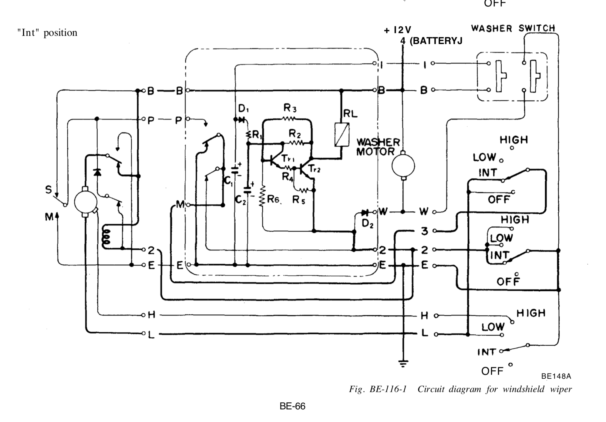
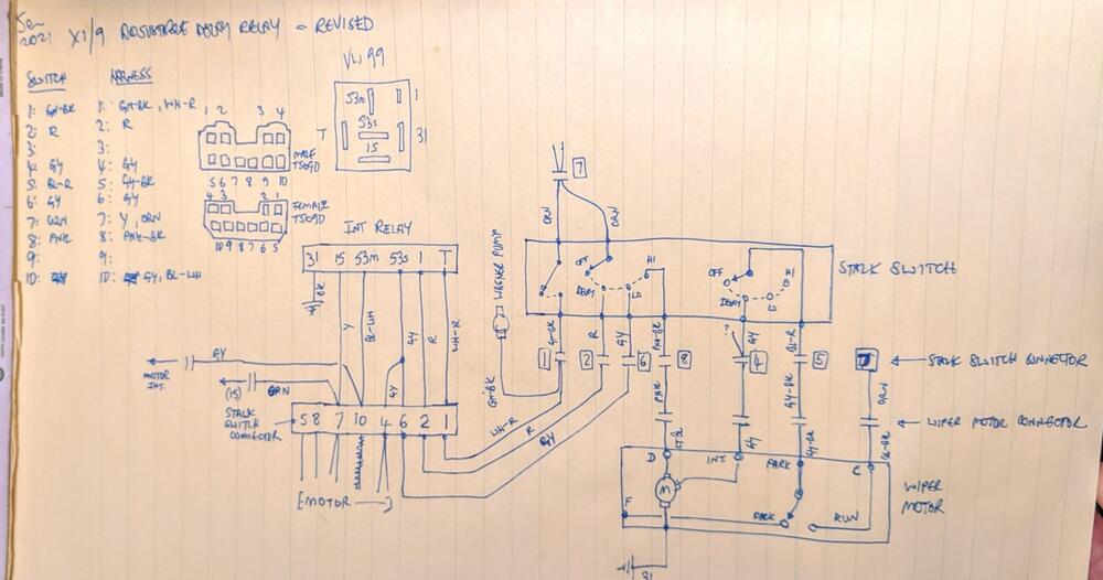
OK - I'll pay attention to that - it appears that B & E pass through the relay in the diagram, so I'll have to pay attention to the actual connections at the relay. What I have to do is overlay the Nissan diagram with either the Volvo or Fiat ones I made to figure out which connections correlate, since they all use different markings on the column switch & relay terminals
-
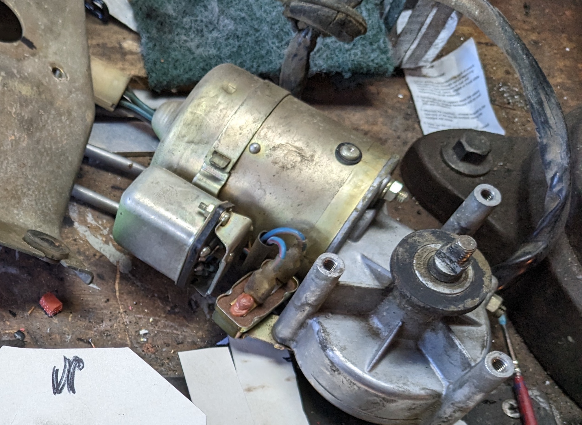
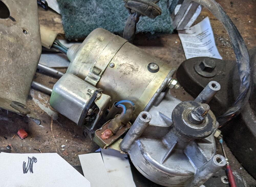
@SteveJ - thank you for your time - that does save me some back & forth 🙂 So, just to clarify, the 'relay' on the motor is considered an integral part of the motor as far as the diagrams go, they serve as the switching component (illustrated in the diagram above) built into most later wiper motors.
-
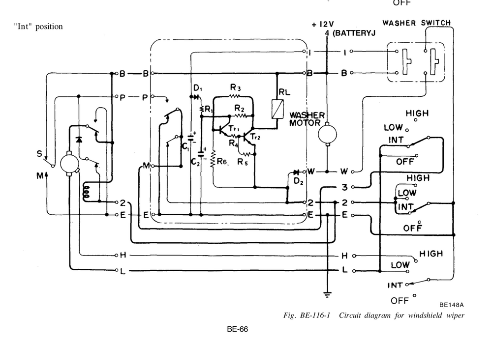
Thanks for the input, Steve. The diagram is pages 66-68 in the BE section (75 FSM) interval sequence. Interval relay shown in center, no indication of the extra parts on the wiper motor There is no need to m oddity the switch. All one needs is to set the switch to interval, turn it off, turn it back on after desired number of seconds and the relay holds that time lapse. I just have to figure out how to mesh the Bosch style relay connections with the Nissan panel, removing the Nissan relay
-
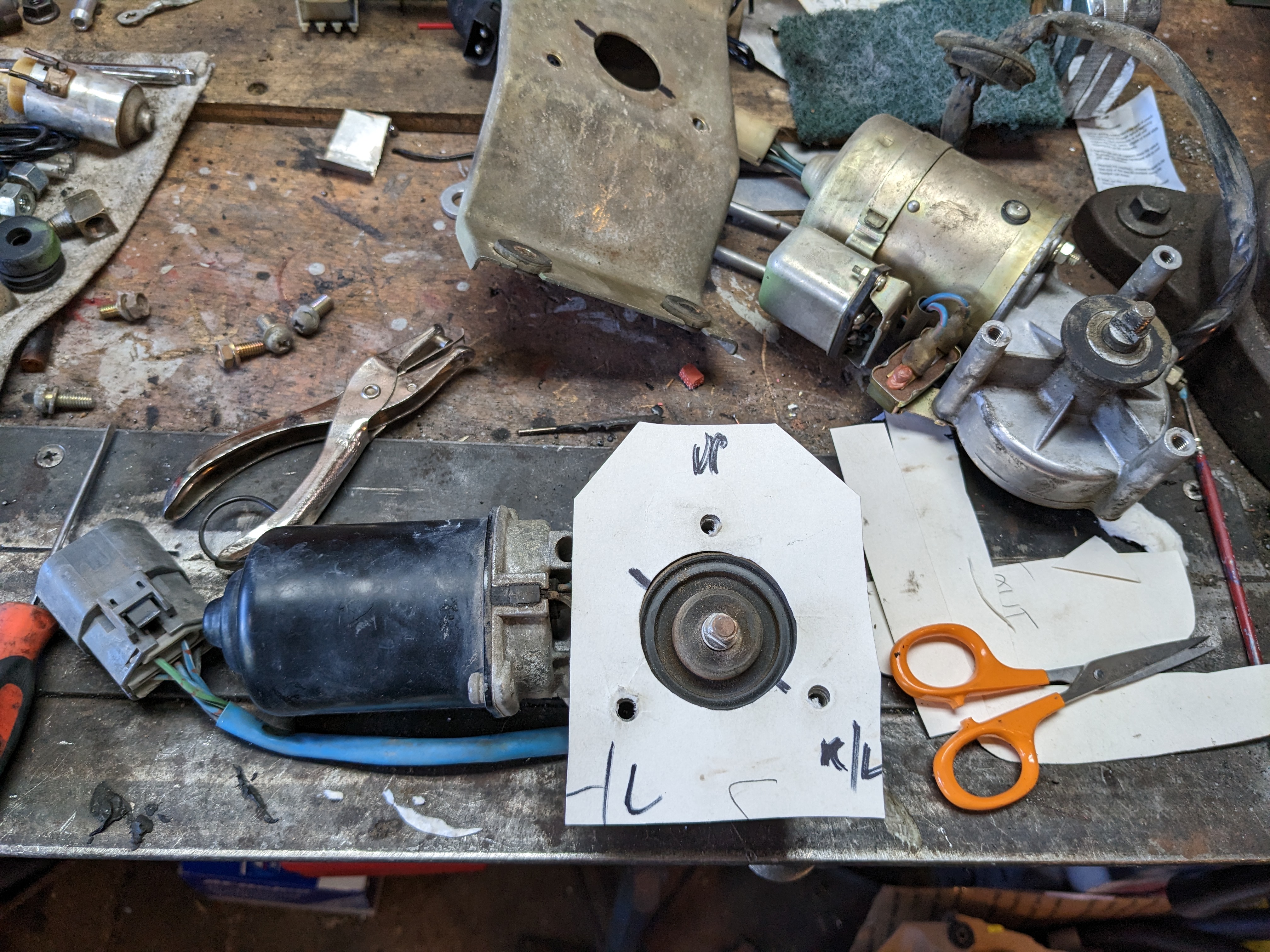
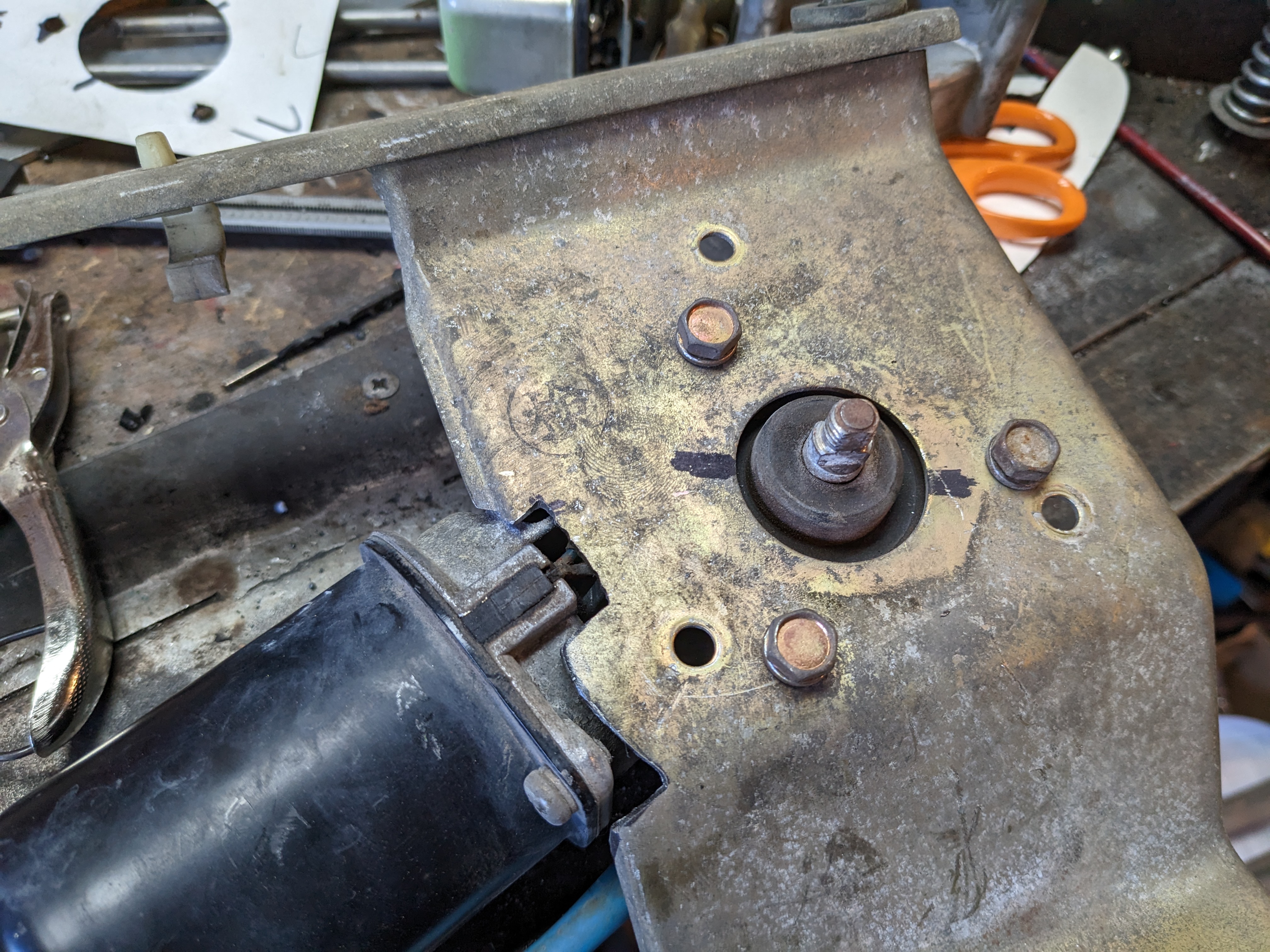
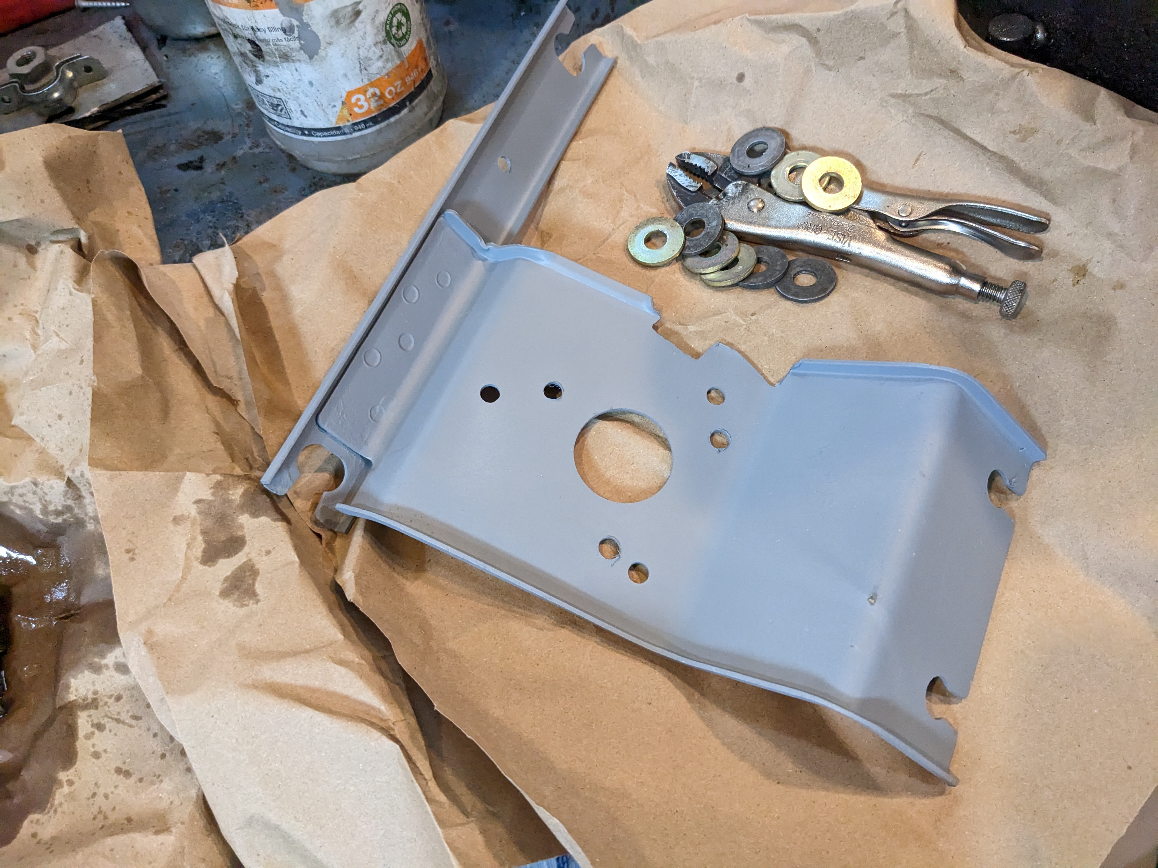
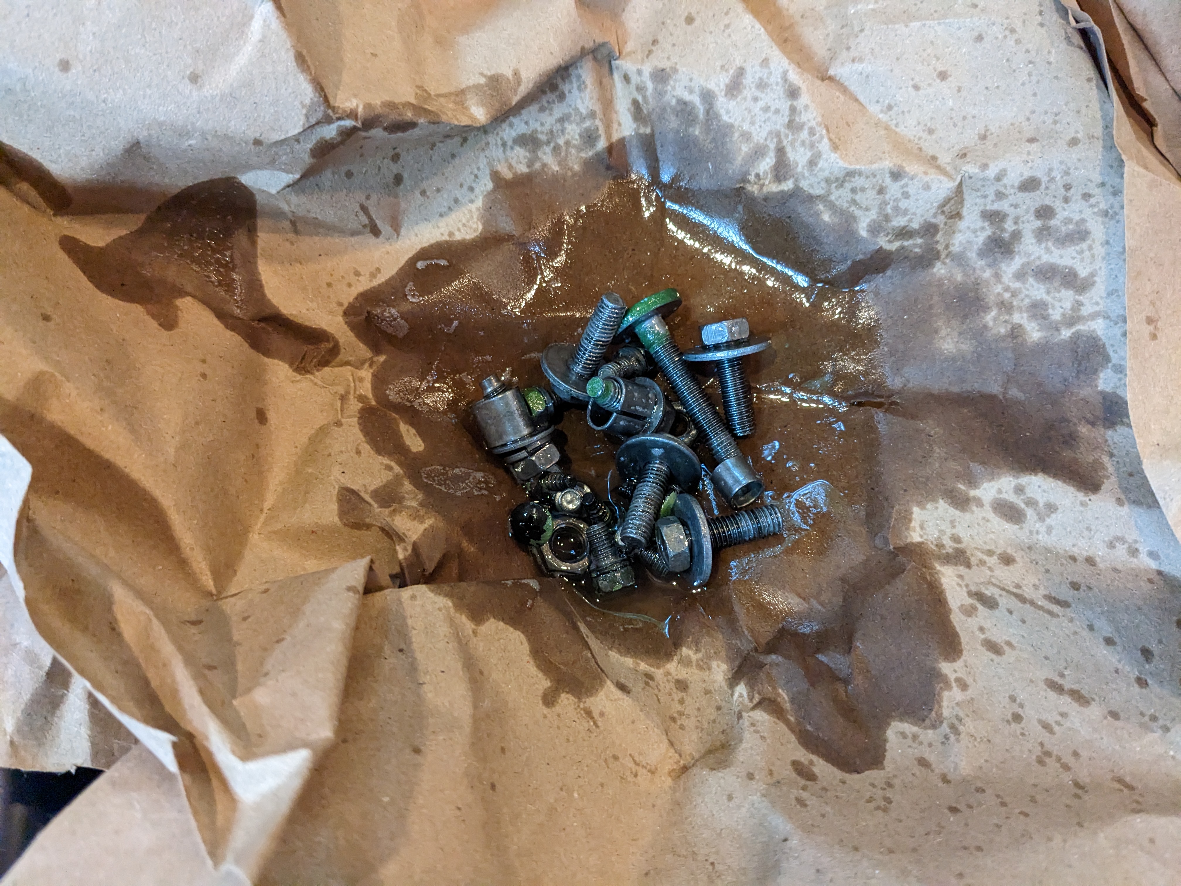
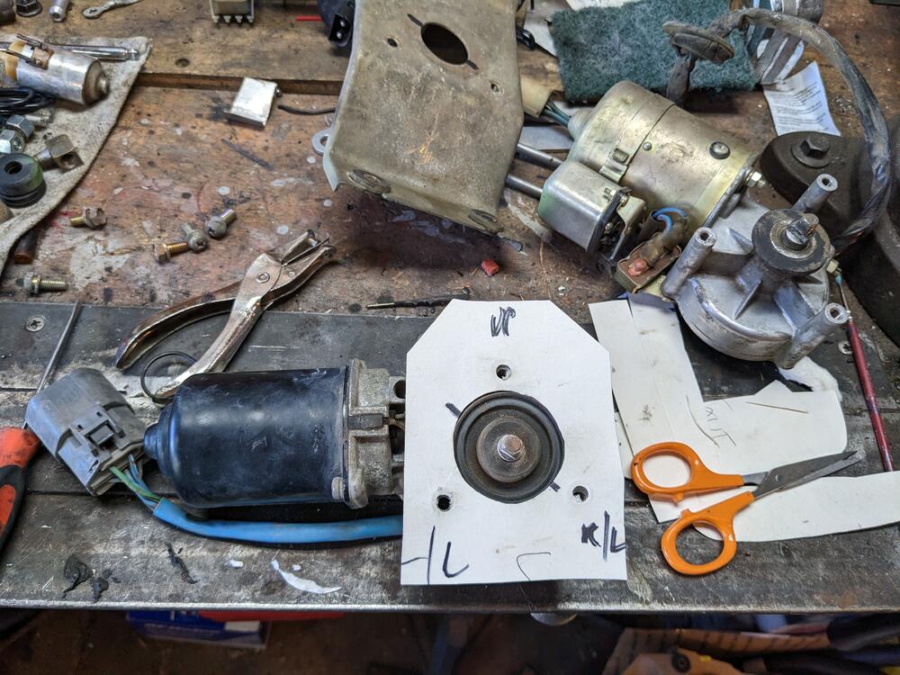
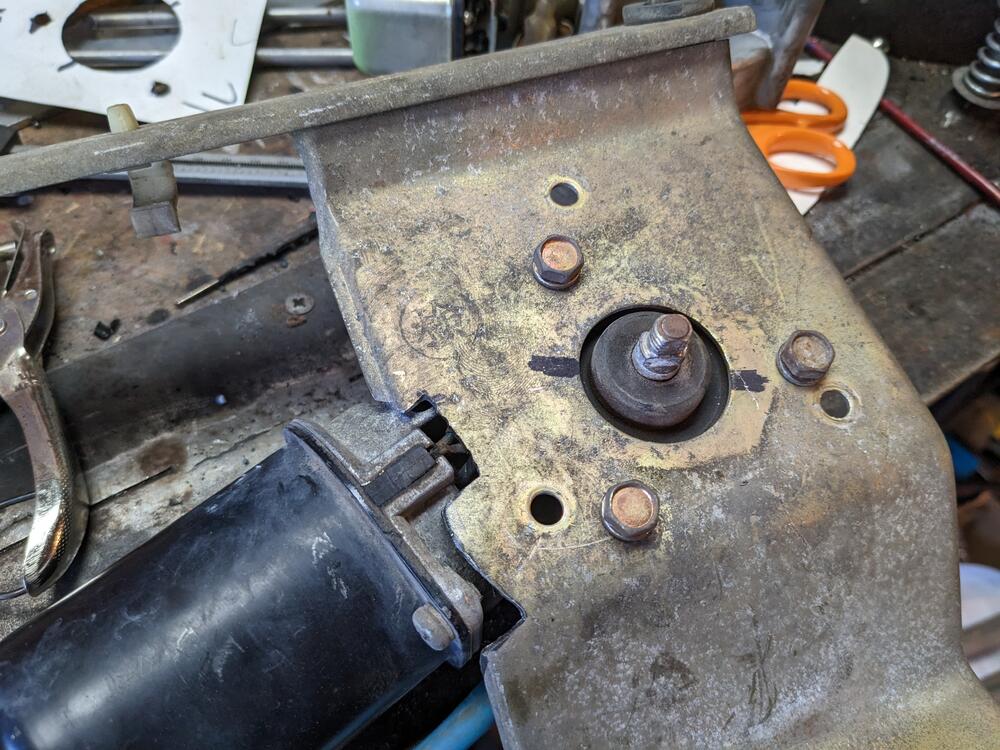
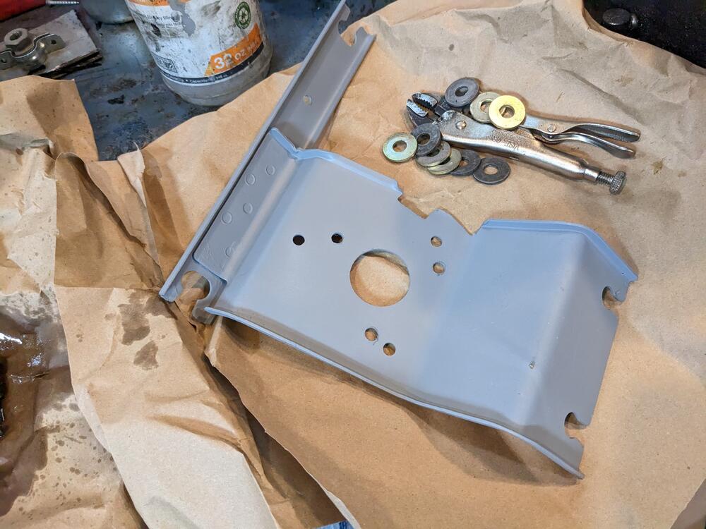
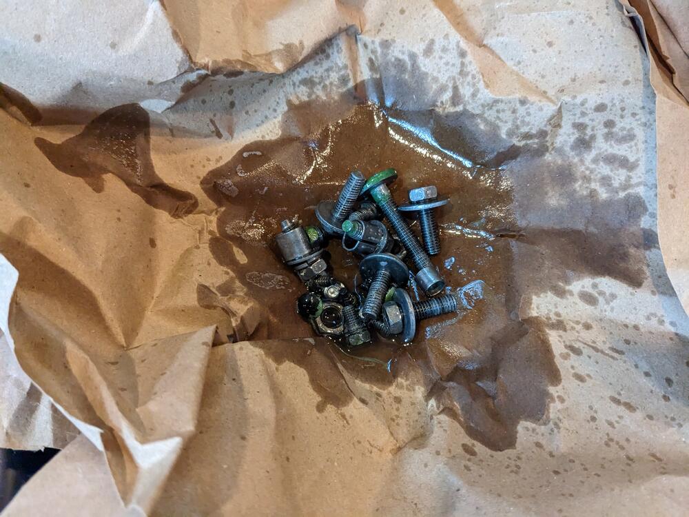
Made a template for the wiper motor mount & drilled & cut the Datsun mount bracket to fit. I offset it so the park position is a close match to the original testing placement again - clears the cowl OK - no contact here bracket etched & primed hardware all prepped as well I put the linkages back in with the base seals and new caps, but I'm assuming I'll have to remove it & attach to the bracket & motor first - I was not able to separate the original in -situ. Any comments on that aspect?
-
The one I bought off eBay (identical to ZcarDepot's image) was off a 98 Acura Integra (complete with linkage for $42), and apparently fits 96-98 Integra and 92-95 Civic also