cgsheen1
Free Member
-
Joined
-
Last visited
Everything posted by cgsheen1
-
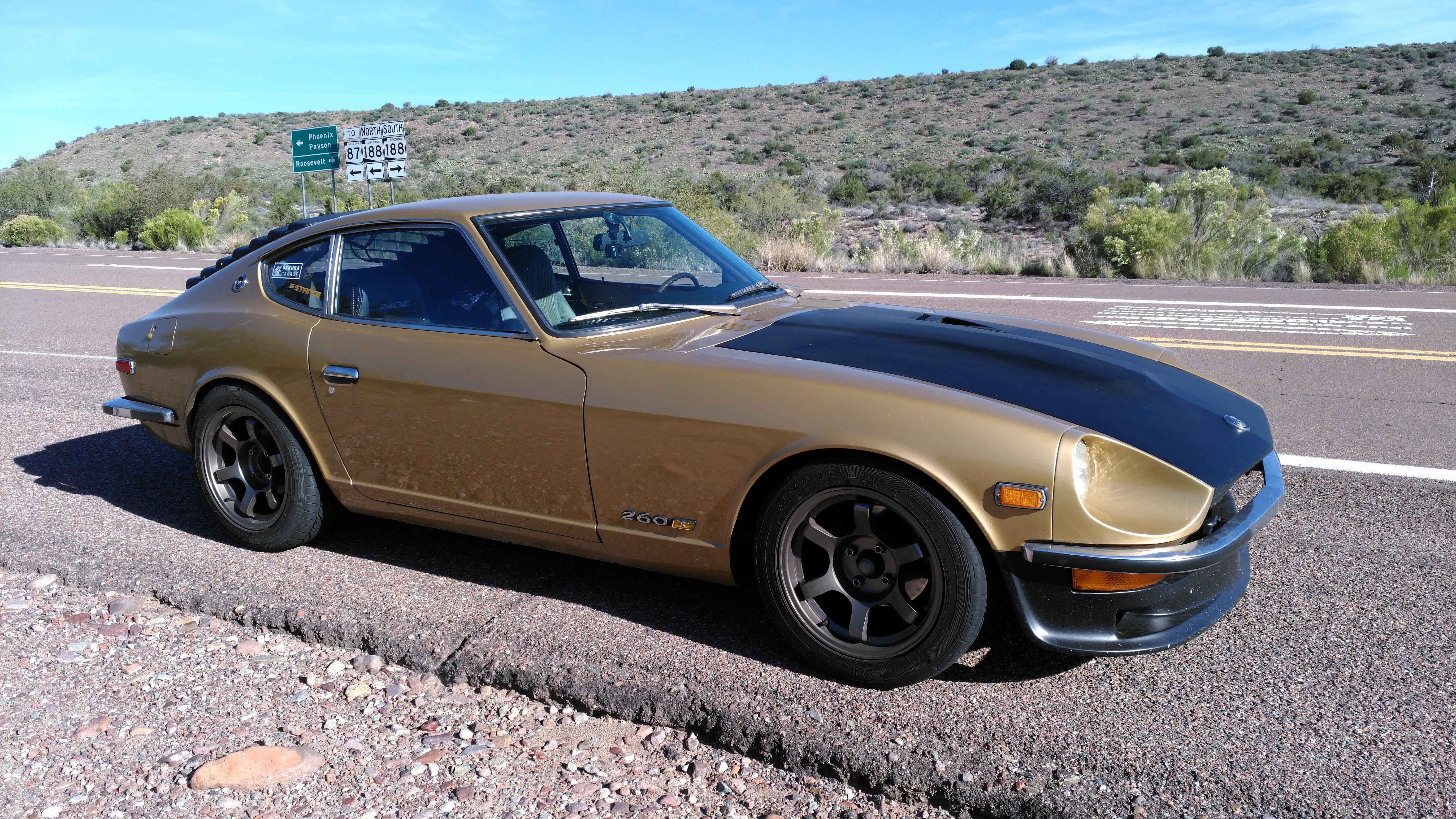
 Had a Champion, worked a bit better than stock I think but found a much better solution with a 240Z KOYO radiator. Been using the KOYO with my intercooled, turbo-swapped, (early) 260Z with factory A/C, here in PHOENIX, Arizona (not name dropping, just emphasizing the HEAT factor...) for a few years. In my estimation it's much better than the Champion I had - or Mishimoto radiators I've seen in some Z's here in Phoenix...
 -
Grab a torch - propane will do - and melt the body lead out of that section. That'll give you a better idea of how that sheet metal is shaped and spot welded together. There will be body lead in various places all up and down that pillar. The lead will probably have saved the sheet metal up near the window flange - and may give you a good clean section to weld to at that end.
-
But if you look at the diagram, the G/W gets Battery Voltage in the START position of the IGN Switch. (The circuit provides a bypass of the Ballast Resistor when cranking the engine for start - once started the juice goes through the Ballast Resistor for normal running operation) SO - don't leave the G/W dangling where it could cause a short... could have done that in one post - but I'm old...
-
Very good idea with one caveat - the stock wiring is "50 how many" years old and could be pretty oxidized (engine bay). My OCD would be "new gauge... OLD wire? Naw...". Your mileage may vary.
-
(this is for anyone else interested in a little information about some specifics that you raise:) 1. NONE of the above are "Coil - ". (Stock config = Coil "-" is connected to the points output of the distributor. So, new wire from the Coil "-" to your new gauge...(it will be a 2nd wire connection as the Coil "-" needs a "signal to fire" from points or an electronic ignition unit as well - your new gauge is just tapping into that signal)) 2. You don't necessarily need to jumper any of the wires in that connector, but you need to understand the coil wiring to decide whether to JUMP or just ABANDON the G/W and B/W in the connector pictured above. The stock circuit goes like this: IGN SWITCH -> B/W -> Ballast Resistor -> G/W -> Tach connector -> Loop on back of Tach -> Tach connector -> B/W -> Coil "+". The coil gets power at IGN ON through this and the Tach "senses" the flow of electricity to the coil. If you're replacing the stock Tach, the re-route of the B/W back to the Tach is not necessary - the B/W and G/W to that connector can simply be ignored (abandoned). SO - the B/W that goes to the Ballast can be connected to the Coil "+" - either through the Ballast (by removing the G/W and running a short wire from there to the Coil "+") OR bypassing the Ballast and connecting the "ballast's" B/W directly to the Coil "+" instead - IF you no longer need a Ballast Resistor in the circuit. note: I think it's better to abandon and get all that extra wire (and added resistance) OUT of the power circuit to the coil... BTW, the other two wires in that connector: Black - is a Battery Ground. R/L is gauge lighting - it's listed in the wiring schematic as "IL". So Black is the power ground for the Tach - the Tach gets power (battery voltage) from a Green in another connector.
-
Awesome.
-
Or a new flare on that tube and maybe a new flare nut. I'd venture a guess that it didn't go 6 years without any leak at all - probably just one that was slight and unnoticed... (just like many plumbing leaks)
-
It's quite amazing the problems in the plumbing world that arose with the change of season. Especially when the atmosphere went from warm to cold...
-
Automotive upholster... I think the best tool for cutting foam is a hotwire cutter but that isn't for the faint of heart.
-
The FSM describes how to adjust the horn sound and its actually very simple (screw on the back with a locking nut). Not saying they'll sound like a Jag, but altering the way they sound is possible. I believe each horn is set to a different tone.
-
There is a point where the adjusters will cease to tighten. If they're working properly, they shouldn't be the cause of a sticky drum removal. There are other factors that could be the cause. IRL the drum shoe friction material isnt that thick and they don't see that much use so there really isn't that much re-adjustment needed over time. I daily drive my 260 and have changed shoes once in 14 years. After you have them set properly you won't notice much if any park brake handle lock position change.
-
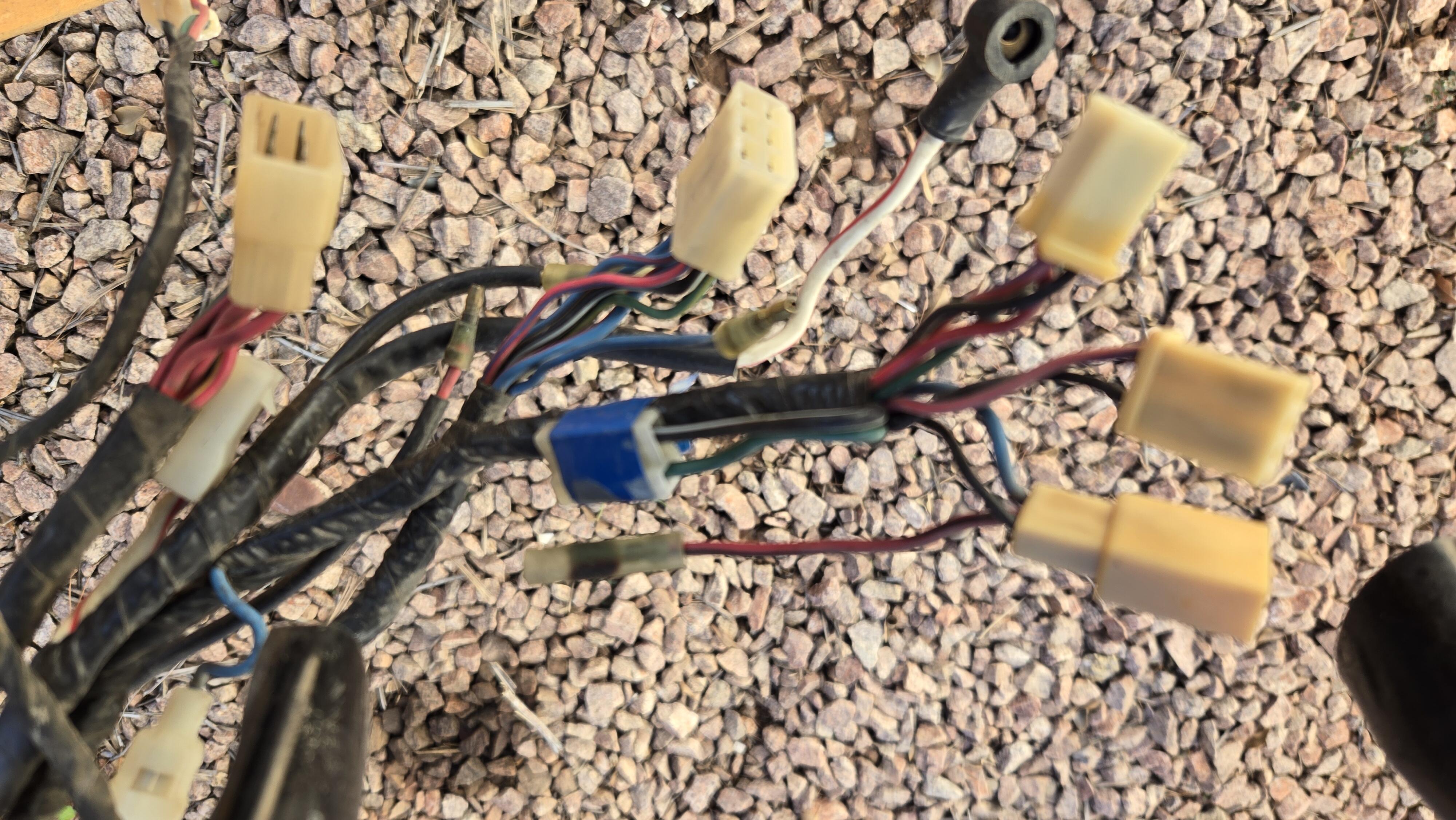
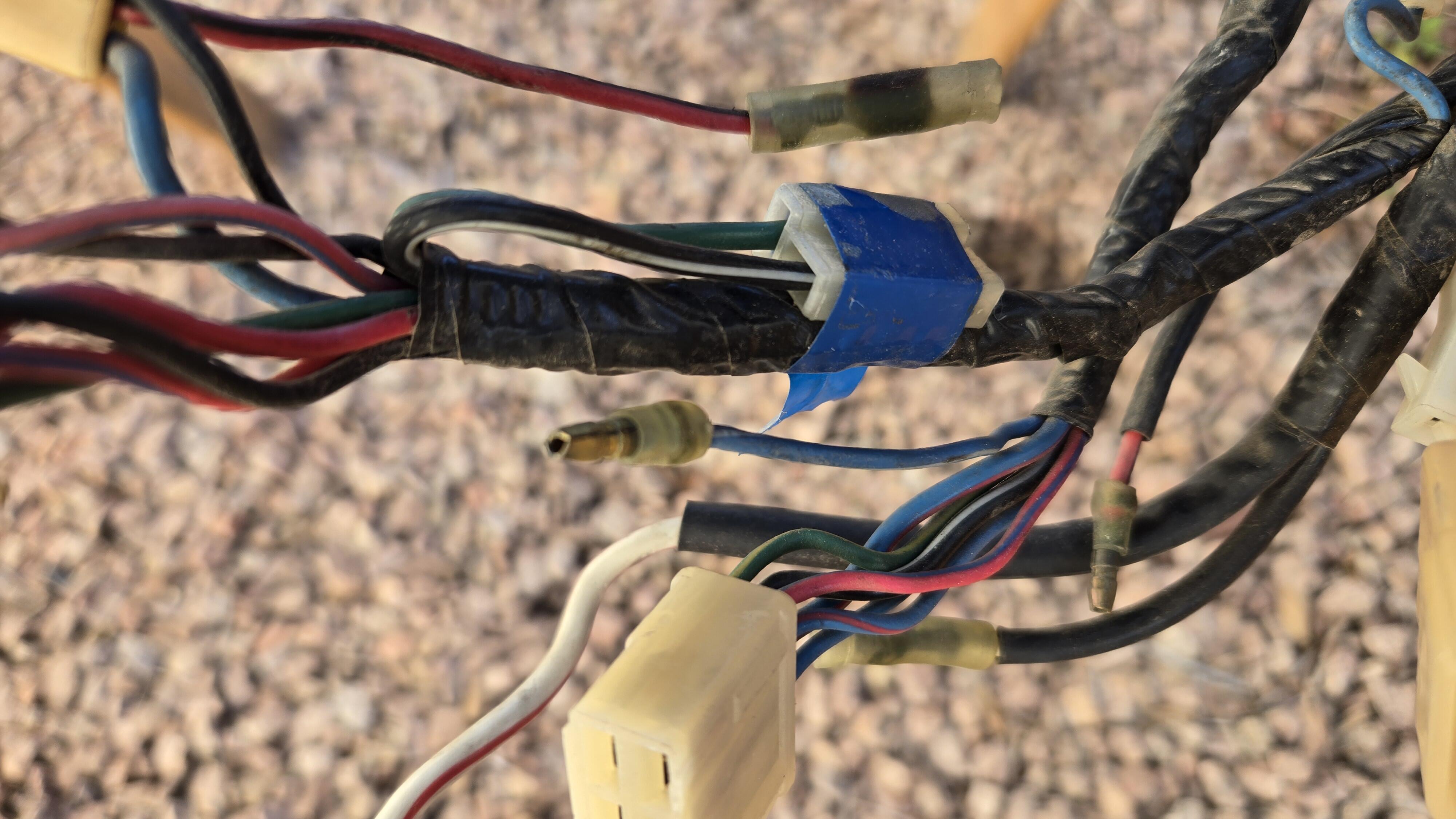
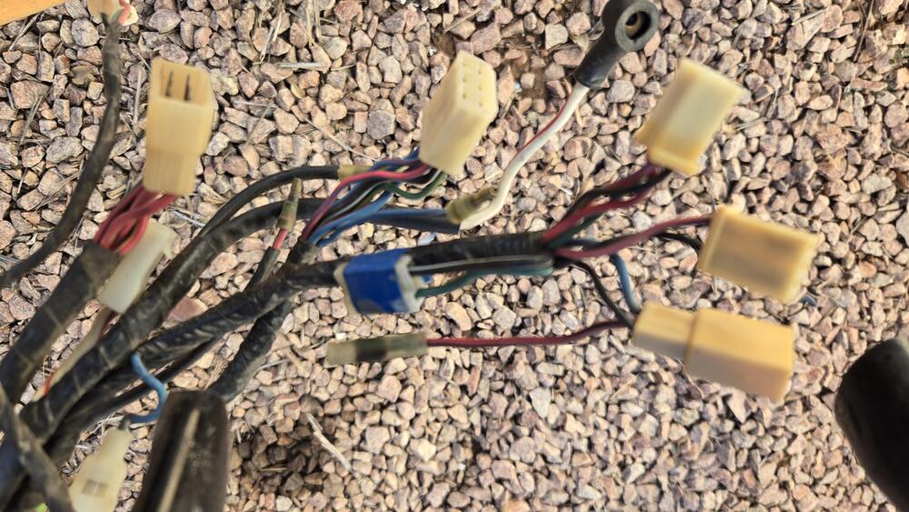
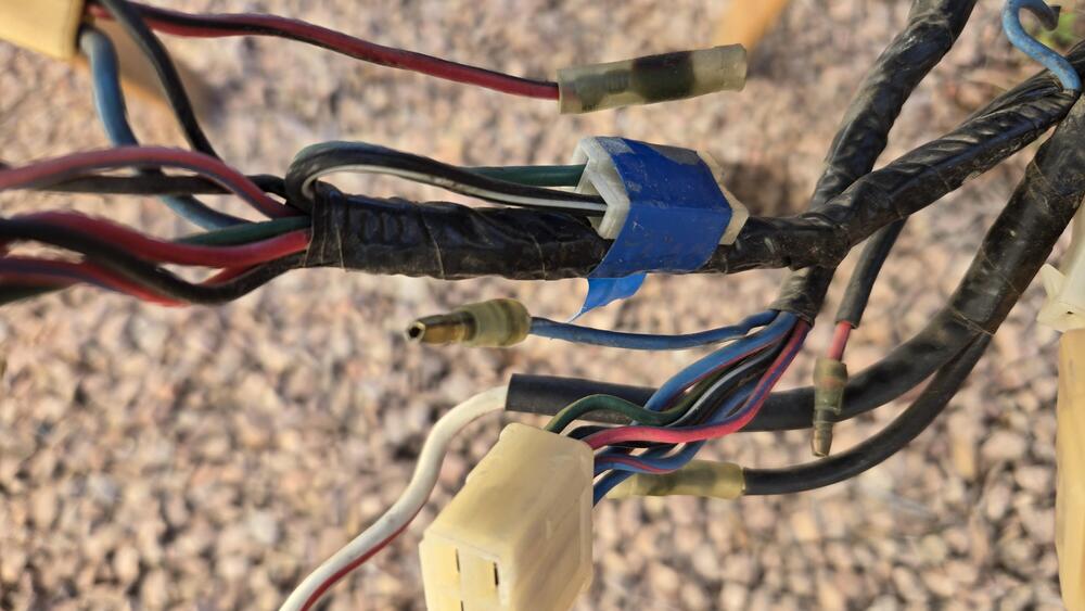
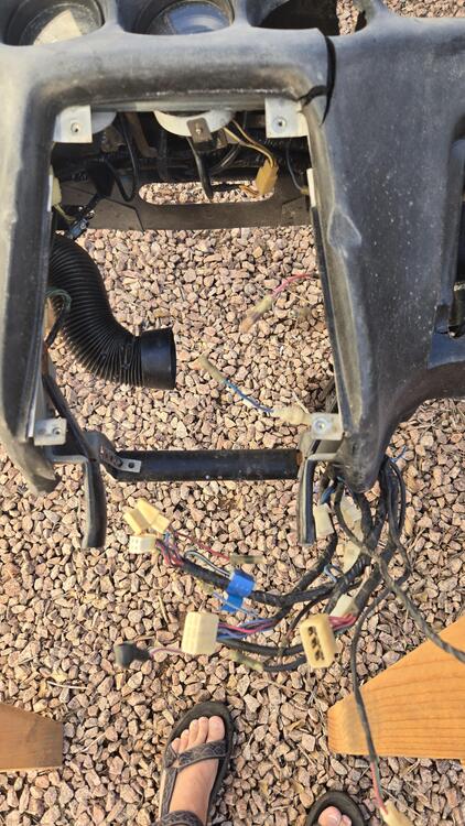
Sorry, this 240Z dash is not in the car but here are pictures of the dash wiring and the unused connector that could deliver power back to a fuel pump. The wiring comes down the right side of the heater slider assembly with all the wiring to the fuse box and center console connections.
-
🤣 OMG... I used to do that... Thank goodness I haven't seen a phone cord in decades!
-
The cup or the embossed piece holds the spring and the small hole keeps the pin centered. I'm sure you've seen a spring that has slipped to one side - now you have spring steel that is potentially causing wear on the pin and backing plate due to it's abnormal position.
-
Don't forget the 2 rubber plugs underneath the back side of the hatch...
-
The 20amp fuse referenced in the schematic is probably part of the assembly under the dash (in the vicinity of the fuse box) that Nissan used in the cars that actually had an electric fuel pump from the factory. The "fuel pump connector" under the dash - a 2-pin female with a Black/White and Green wire - may well have been tied together with wiring that included a 20amp fuse. Probably not a bad idea to include the fuse with an impact sensor while you're connecting those to enable power to the fuel pump wiring already in every 240Z body harness. (and again, the reason the electric fuel pump wiring as referenced in the schematic wasn't allowed in the US is the LACK of a "safety mechanism" to stop the fuel pump operation in a collision)
-
My OCD would have me doing both the same BUT I doubt that it would actually matter. The real purpose of the pins and springs is to keep the shoe in place while you get the drum back on and to provide some anti-chatter.
-
The aftermarket hardware kit at O'Reilly's has 8 of those retainer washers rather than 4 retainers and 4 cup washers. One on each side of the spring to keep it centered and in place - would work.
-
That's larger tubing than stock so you won't have any problems. Stock supply is 5/16 and on the 240's return is two pipe sizes smaller I believe. The 260's and 280's got a larger return that's one pipe size smaller than supply. My L28ET runs well with the stock 5/16" supply and 1/4" return. Hard lines and electrical harnesses are the first things that go in when Z is put together. Fuel lines snake from very front to beyond the rear suspension. Portions of the rear suspension are not that difficult to get out of the way.
-
Not a "snark" - just a sigh from a bona fide Turbo Swap and EFI Enthusiast... Always have been and never apologetic. And although I sigh, I never fault anyone else's decisions concerning their own vehicles. A comment is just a comment, everyone has their own opinion, and some have greater experience in a certain sphere than others.
-
-
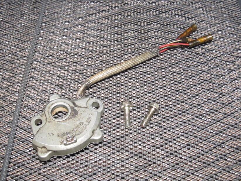
Yes. Gasket and heat shield in one goofy thing..
-
I used aluminum aircraft rivets - and like your pop rivets, I should have used a semi-tight washer on the squishy end. The sheet metal on the contacts is really thin. I also "re-squished" the (original) rivets on the bulb holders.
-
-
Posed the question on the interweb and got this "AI generated" answer but it lines up with the automatic transmission info in the 1976 280Z FSM: "The inhibitor switch on a 1973 Datsun 240Z automatic transmission is located on the transmission itself. It is typically found on the right side of the transmission, where it controls the circuit for the reverse lights and the starter interlock system. The switch is responsible for ensuring the car can only be started when the transmission is in Park or Neutral, and it provides a closed circuit for reverse when the transmission is in reverse. For a 1973 model, the switch is specifically designed for automatic transmissions and is not present on factory manual transmissions." (We've had A/T Z cars in the shop and swapped out auto transmissions for manual transmissions, but I honestly don't remember the wiring at all.) The electrical schematic has it wired with 4 wires: B/Y, B/Y, RB, R. (B/Y for the start circuit and R & R/B for the reverse lights) The other relay in question is called "Seat Belt Relay" on page BE-2 of the FSM. Refer to "Fig. BE-1" item 17 "SEAT BELT RELAY (A/T MODEL ONLY)". The FSM shows that with 6 wires (as does the schematic - but the schematic does not label it "seat belt relay"): B/Y, B/Y, B/Y, B, G, G. (B is shown on the schematic as the GND symbol). BE-2 of the FSM shows the seat belt relay mounted on the firewall. Others, in other forums, do describe it as the "K-18". Those are the only ones I see related to the start circuit - I don't think the black box under the glove box should be involved. (Is it the ACC Relay?) And there's a post on ZCAR.COM: https://www.zcar.com/threads/not-the-inhibitor-relay-topic-again-1973-240z.424554/