Namerow
Community Member
-
Joined
-
Last visited
Everything posted by Namerow
-
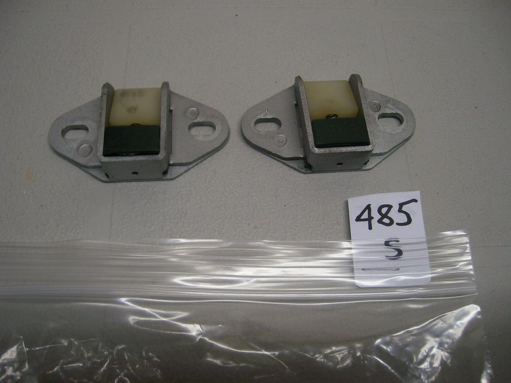
Your photo is a great illustration of how (and why) these parts failed in regular, daily-driver service... 5 years of driving x 1 drive/day x 1 up-down cycle/drive = 7000+ flexes through those two narrow webs of spring steel. Add additional cycles for further use by new owners over some/all of the next 35 years. 'S-N-A-P'! A junkyard piece may have already exhausted a good part of its useful life, so if you're planning on keeping your car and using it a lot, it might be a good idea to grab a spare for the driver's side door.
-
I recommend that you not use Permatex spray adhesive (a common offering in auto parts stores). Use, instead, 3M #08088. I have found that the Permatex product 'gives up' with time. I've had much better results with the 3M product. Also: You will find that some contact cements aren't compatible with foam. Because the heater box is something you will hope to never need to remove from the car again in the future, you do not want to discover months down the road that your new flap door padding has started to peel off.
-
@kats Thank you for investigating. This is the equivalent of about US$400. When compared with the current price for a rebuilt unit -(US$200), that seems a reasonable price for a comparable-design, new-old-stock Nissan part. As you note, however, only the internal parts are useful for the owner of an S30. If you have the time, would you please ask your Nissan parts source whether either of the original re-build kits for the S30 MasterVac are perhaps still available? They are: KIT-A REPAIR FOR MAS - 47210-E4625 KIT-B REPAIR FOR MAS - 47210-E4626 (includes Kit 'A', plus the plunger, check valve, and filter-silencers) According to the manual, these kits were designed for use only with S30's produced up to Aug. 1971. There is only a small possibility, I know, but I think worth investigating.
-
Maybe @katscould do some checking for a source in Japan?
-
@zcardepot.com Interested in pursuing the possibility of approaching Cardone, or similar, with a proposition like this?
-
IIRC, Steve Nix took a pass on replicating this piece because it's a safety-related item and would expose him to liability in that one failed in service. Other low-volume parts casters will probably feel the same way. The big parts rebuilding operations seem to have access to a source (although perhaps only because they purchased in volume from Nissan Service Parts years ago when the Z's were still 'current' and are now just working down through their inventory). Seems questionable whether a rebuilder like Cardone would be willing to sell just the diaphragms -- even in a lot of a couple of hundred -- because it would be undercutting their primary business. Still, maybe somebody like zcardepot.com might be willing to approach Cardone's business office with just such a proposition ("Sell us a hundred of the diaphragms and we'll carry your full rebuilt units in our catalog, too.')
-
240260280 posted a detailed, DIY mastervac rebuild article on the old AtlanticZ website several years ago. Have you seen this? (I can send you a copy). He used RTV sealant to repair the diaphragm -- apparently with good results. My guess (valued at 2 cents) is that 95% of the vacuum failures are due to cracking of the diaphragm, rather than failure of the poppet valve. The extent to diaphragm issues are accompanied by leakage from a corroded pushrod is probably related to whether the car lived in the salt-belt or near an ocean. According to 240260280, the pushrod problem can be somewhat easily remedied.
-
I had mixed results trying to remove scratches on some side windows. They appeared to have been made by PO's trying to scrape off ice using some kind of metal scraping edge*. I was using a bench-mounted buffer and an aggressive buffing compound. Glass is hard. If it's been deeply scratched by a sharp metal edge (like a wiper arm when the rubber blade gives up), don't expect miracles from what is essentially industrial-grade toothpaste. That said, there are materials harder than glass (diamond dust comes to mind). If you can find and afford whatever that compound might be -- and I'm sure it's out there, somewhere -- then it might solve your problem. In the end, though, my guess is that a new windshield will be the better solution. (* If you live in Canada, you'll know that there's a certain kind of desperation that sets in when it's below 0 degrees F, the wind is howling, it's snowing hard, you need to get to work, and your windows won't go up or down because there's a layer of ice gluing them to the weatherstrip).
-
My point, exactly (and a very nice piece of fab work by our friend in Ft. Saskatoon). Try replicating the overall panel with pieces of 'box board' (aka packaging from a grocery store frozen pizza), using masking tape to hold the pieces together. The box board will only be happy bending in one plane (kind of like 18-gauge steel). Might take a few tries to get down to something you're happy with, but pizza is cheap (and goes well with beer). Also worth remembering something the you, yourself pointed out at the beginning of this project, that being that nobody's going to see this panel after the car is finished and on the road. All you're aiming for is a something that's structurally sound and fits. Applauding your work from the sidelines.
-
It's been pointed out by many that it can be a lot more fun -- on public roads, not a racetrack -- driving a low-limit car at its maximum, rather than being frustrated or intimidated by a high-capability that can't be used to its capacity. An MG-B or TR4 driven to their (meager) limits can be just as entertaining as diving into an off-ramp at 80mph in a performance car while only using 80% of the car's real capability. Fat tires look great, but they don't necessarily add enjoyment.
-
You're a confident welder. Maybe you should stop trying to think about forming difficult shapes from a single piece of sheet. Yes, it can be done... but do you really want to go down that path? How about forming smaller sections and then tacking them together?
-
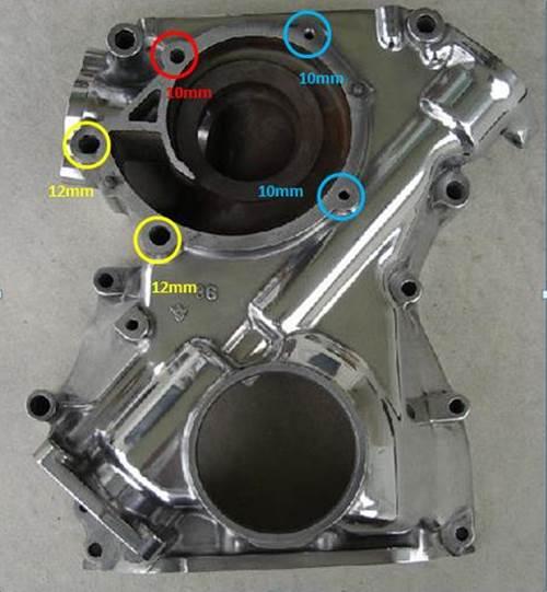
I wonder how many thousands of Z's suffered from this particular affliction. The problem bolt is the 10mm (M6) item located at the 10:30 position... x I think that innocent-looking bolt head probably fools a lot of first-timers because it conceals the fact that the hole in the timing cover is just a pass-through, with the bolt actually threading into the front face of the engine block. That means there's an inch or so of freestanding length sitting proud of the block face -- permitting just enough wind-up under wrenching torque to trick you into thinking that the threaded part is starting to move. And then.... 'SNAP'. Just for fun, I simulated the set-up by locking a 10mm bolt (6mm shank) in my bench vise and then using an old-style torque wrench to see how much torque it would take to snap the bolt. I located the start of the threaded section right at the face of the vise jaws, with the 1-1/2" unthreaded length sitting about the jaws. IIRC, the bolt broke at under 10 lb-ft! . I was just using a hardware store bolt, but I don't expect that the Nissan OE bolt would offer much more than double the strength. So the threshold between, 'I think it's moving' and 'uh-oh' is about 15 to 20 lb-ft. If the bolt was infinitely strong, I'll bet it would take 30 - 40 lb-ft to break the frozen threads free. So it looks like a losing proposition if your only solution consists of leaning on the wrench just a little harder. Just for comparison's sake, the bolt torque reference chart for ISO fasteners that's included in Wick Humble's 'How to Restore Your Datsun Z-Car' indicates that the recommended tightening torque for a Grade 4 (per the OE Nissan item) M6 bolt is just 2.5 lb-ft! (and only 6 - 8 lb-ft for the heavy-duty, Gr. 9 version). The L-Series FSM is notably silent on recommended tightening torques for these types of secondary fasteners. What a contrast! Install = finger-tight. Remove = beyond snapping point.. The two other 10mm bolts have their own problems. Just like certain other bolts on the L-Series engine, you have a steel bolt threaded into an aluminum casting, so internal corrosion sets up because of the dissimilar metals. I've had good luck with these timing cover bolts on two different engines by using a small, handheld impact driver and a medium-size mechanic's hammer. Just takes a bit of patience (along with removing the radiator).
-
I discovered the SAE thread anomaly, too. I can't remember what I used as the puller cross-piece (maybe my generic steering wheel puller), but my recollection is that it really didn't take much force to make the harmonic balancer free up. I'm pretty sure I just used hardware-store grade bolts. Why not give it a try before you get too worked up about trying to find high-strength bolts? The balancer is a tight sliding fit, but not an interference fit... ... unless there's been corrosion at work.
-
PM me and I'll send you contact details for the specialist I hired. He caters to dealer service department jobs and is extremely competent. Golden Horseshoe coverage. Price is reasonable for job-done-right.
-
Good summary of Z buyer mentalities. Nissan put a lot of improvements into the 280Z's design, delivering a car that was a lot better daily driver than the original 240Z... and that was what was needed to hit the target market of the day. Unfortunately, those improvements don't really matter to buyers of a 40-year-old 'classic car'.
-
I believe this is probably related to rear-end collision protection (and maybe also protection from electrical sparks). It might also have to do with protection from shifting cargo in the hatch area. Or all of the above. Safety considerations were pretty thin when the original S30 design was laid down in the mid/late 60's. They ratcheted up significantly throughout the 70's. Consider: A tank sitting behind the rear wheels that's filled with fuel vapors, connected to the fuel tank by cloth-covered rubber hoses. Did any other cars of the era use this particular placement for the vapor recovery tank? For possible clues re manufacturer's motivation, see: Ford Pinto.
-
These dampers get added when a manufacturer discovers an unwanted truth about their drivetrain after it's too late to come up with a more elegant solution. And you know how car companies hate adding invisible items to a vehicle that don't add to the profit margin, so there has to be a substantial problem before they'll add something like this. When I worked with a manufacturer (who shall remain nameless) on the public launch of one of their prestige-class models ten years ago, I found a very similar device attached to the rear diff casing on the versions with the optional AWD powertrain. And this was well into the era of CAE, FEA and computer-driven lab-baseddrivetrain testing. I expect that the usual issue is a buzz or drone at a key highway cruising speed. An 'enthusiast' owner, of course, may never notice the issue.
-
Try Vintage Connections (west coast) and Eastern Beaver (east coast, IIRC). They'll be your best bets (esp. Eastern Beaver, who sources from Japan). Otherwise: If you need to be original-equipment: There are dozens, if not hundreds, of rusted out Z hulks that are waiting to be your parts donor. If you don't need to be OE: Either Motorsports Auto or Z-Car Depot (maybe both) has a headlight connector kit available and is waiting to receive your order.
-
Why don't you just go to Z-Car Parts of Arizona for these? They're quality parts vendor and basically located in your backyard.
-
I bought pair from a vendor called DatsunLandSoCal several years ago. They install with metal clips (from the underside, so not visible) rather than staples and I am very satisfied with the shape and dimensions, the appearance and the installation system. They sold at the time for over $50 for the pair, so not cheap. Unfortunately, the seller seems to no longer be in business. Somewhere out there, there might be a roll of this rubber, waiting to be put to use. Where is it?
-
Here's a picture of that tool, copied from 240260280's rebuild write-up on the old AtlanticZ website. A pragmatic solution (and environmentally sustainable, too!)

-
I was reading this thread out of idle interest and decided to check out Jim's recommendationre the EZ-Clip hose fittings. Look's like a great solution for aftermarket AC installers. Check out this Eaton Corp. video for details... http://www.eaton.com/Eaton/ProductsServices/Hydraulics/HoseHoseFittings/TransportationHoseProducts/ACRefrigeration/ezclip/index.htm
-
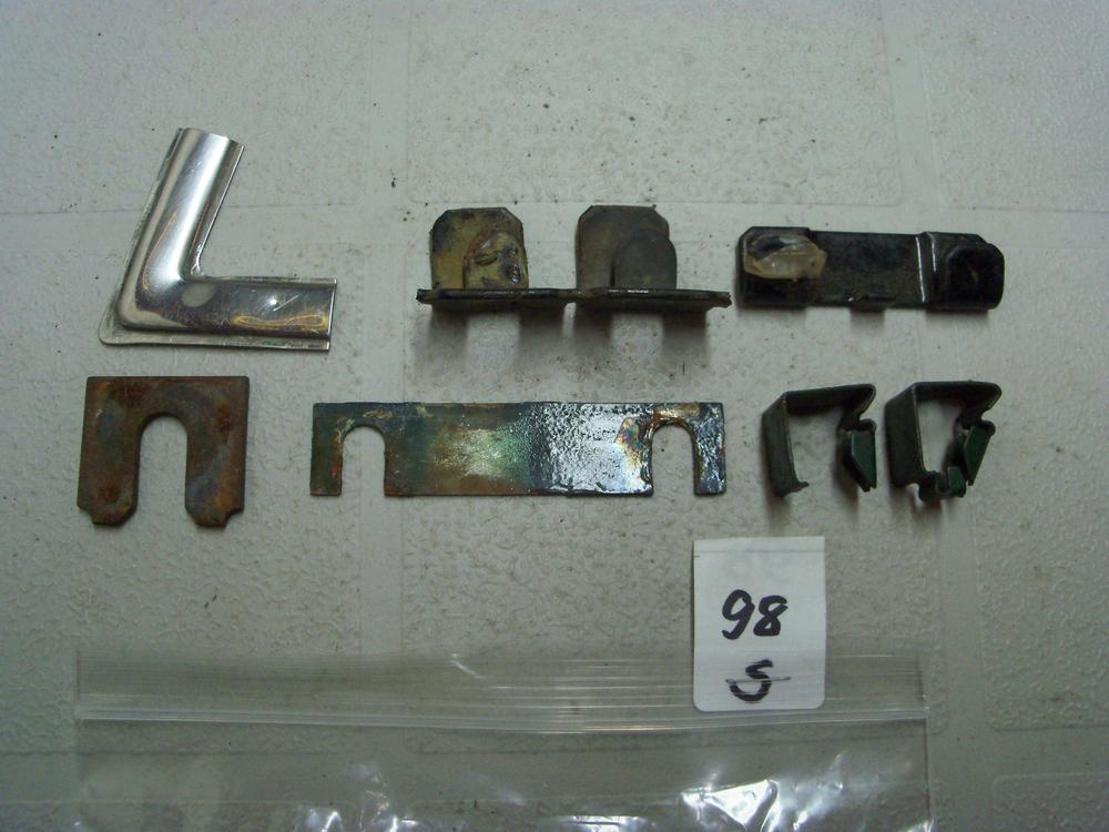
Among all of the assorted little bits of hardware that I've accumulated over the years is a 'slotted' shim plate (lower row, centre, in the photo below). I could never figure out what it was intended for... until now! If you find that you need something like this, it shouldn't be that difficult to to make up a pair from some sheet stock. Maybe make two or three pairs, so that you can stack them. If you go with metal, rust will be an issue so brass would be best (if you can find it this thick). It might be easier and better, though, if you make them from 1/32" or 1/16" clear plastic sheet stock. A little more fragile for installation, but easier to fabricate and zero rust issues. A quick cruise of your local hardware store's shelves should turn up lots of items that could be used as material donors.
-
If the locating pin on the old control arm was bent, you may want to check for frame damage back there too. Look for a wrinkled wall on one of the reinforcement 'ribs'. At some point in its life, the car may have slid off the road and smacked a curb with the rear wheel (easy to do in the snow). Probably a separate incident from whatever caused the frame twist up at the front. Hopefully, it just bent the LCA pin. Maybe somebody else who's seen similar LCA damage like this can comment.
-
Here you go...