
Zed Head
Community Member
-
Joined
-
Last visited
Everything posted by Zed Head
-
You didn't show that you confirmed that you had power to the coil's + terminal. With your previous smoke show maybe you damaged the coil's power circuit. The ZX "match boxes" do go bad.
-
It's in the BE chapter of the FSM.
-
-
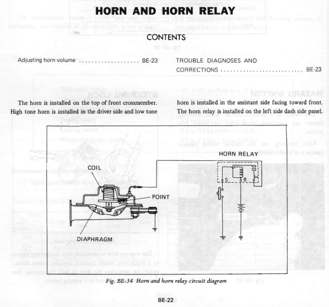
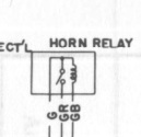
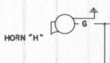
I couldn't post on your post about downloading the diagram. So I picked this one. I doubt that 7tooZ will be bothered. There's another diagram in the BE chapter that supports what TerrapinZ shows. Kind of weird that they don't just run all of the power through the horn button.
-
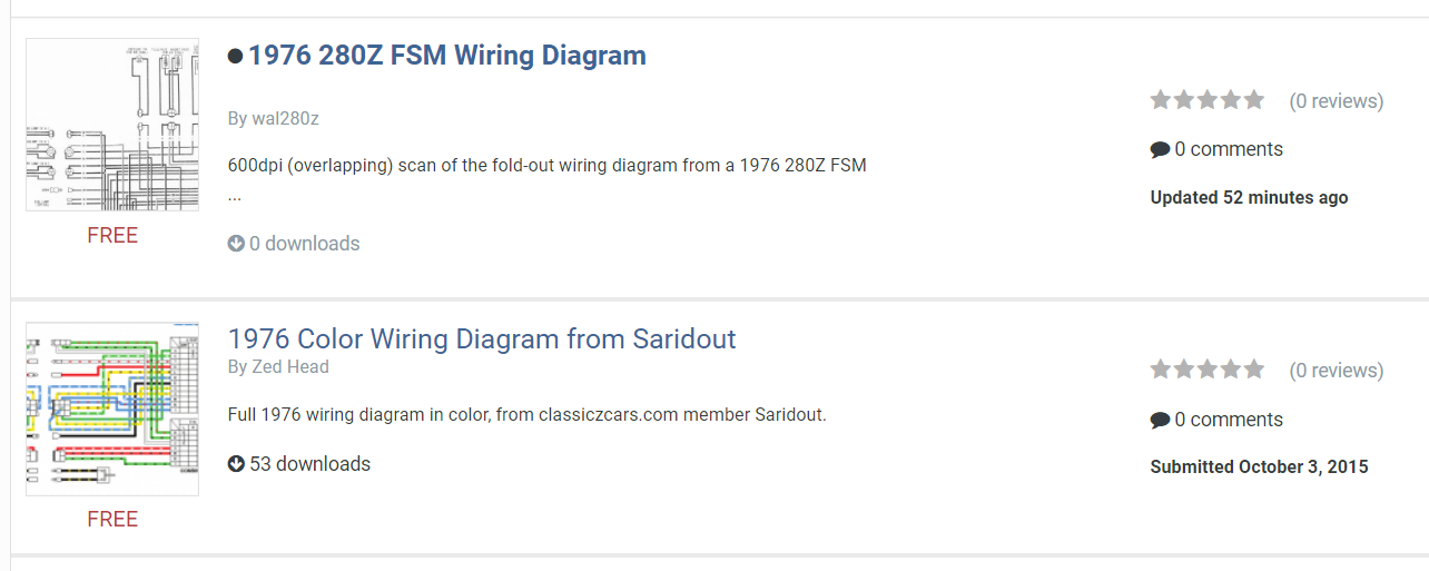
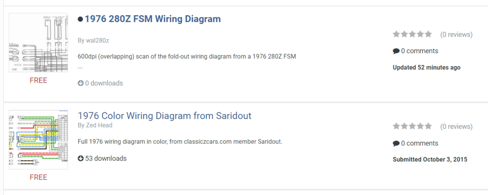
Wayne, Saridout produced a color 1976 diagram quite a while ago. Is it different than the black and white one you just uploaded? We seem to have some confusing redundancy in diagrams and FSM's. For example, some of the 77 FSM's appear to actually be 1976 FSM's. That's why there's a "take II".
-
-
-
-
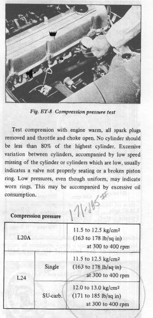
Have you been driving it or has the car been sitting? The FSM has specs. and procedure. The gauge can affect the numbers, but the range variation is what's important.
-
-
Who is Wayne? Don't know everyone's name. The red versus brown controversy has been around for years, at least ten. Even more confounding is the internet data out there that suggests that the smaller brown 0.3 mm^2 link is actually a thicker red link capable of more amps, 0.69 mm^2. The advice is often used for people switching to Maxi-fuses. Nissan stuck with brown through many years of FSM. Somebody decided it was a thicker red link years ago and that advice has been used and abused since then. Notice that there is no Brown in the web-link below, and Red appears from nowhere. There's no Red in any of the FSM's. Either Nissan chose the wrong color and the wrong cross section, and never fixed it for many years, or somebody made a mistake and never corrected it. I've been bringing this up ever since I joined the club. http://www.atlanticz.ca/zclub/techtips/fusiblelinks/index.html
-
-
Looks like you pasted questions from another forum in to this one. Looks like you'd like to restore it to a Type A transmission. By "bend" I meant heat the lever using a torch and bend to a shape that doesn't require any metal cutting. Many possibilities. Here's a couple of old threads on it that are pretty good.
-
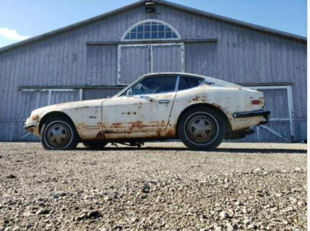
They have a pretty cool barn though. Snohomish is in the wet part of Washington. It was probably back in a corner...
-
Depends on what you mean by "sort it out right". There is no 7/71 Type B console. There are other ways to get the Type B to work with all of the original Type A parts. The most effective seems to be bending the shift lever.
-
It has an automatic transmission. Booooooo.....
-
A hard freeze could probably do that. "Freeze" plugs aren't really there for freeze protection.
-
Can't tell where you checked for vacuum. Is it possible that the check valve is in backwards, or that something is blacking vacuum from the booster body? Or maybe something is bound up in the booster itself, not letting the vacuum do its thing.
-
-
If you disconnect the hose there, there will be no fuel flowing through the FPR. Take the FPR out of the flow path to see if it is clogged. You'll have fuel flowing only through the rail.
-
You must have a 78 rail and FPR. So that takes out the connections between the rail pieces as the problem source, it's a one piece rail. There's only one connection left. If you still get 50 psi from that spot there's something clogging the rail. If pressure drops the problem is in the FPR. That's one crusty looking FPR.

-
Couldn't tell if it was smoking because the key was on or because the battery was connected. A better way to test the wiring before connecting the battery is to measure resistance between the positive cable terminal and the negative cable terminal. A short circuit will show up as low resistance. Then you can go wiggle and disconnect various circuits until the short circuit is found. You can do the same when turning on the key. All circuits should have some resistance.
-
A lug nut on the threads will give you something to hold on to for spinning. Same pitch and size.
-
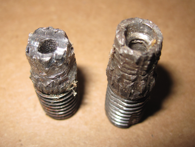
The thoughts above were developed while I was working on my own spindle pins. I found that the area in the bore of the casting around the lock-pin was deformed, as well as the spindle pin in itself. A rat tail file will clean up the bore.
-
You don't need a precision fit, as Dave WM says. Making it looser is probably actually bad for it in the long-term because it gives it more room to flex in the bore, concentrating load on the lock-pin area. The purpose of the very tight fit and the lock-pin is to make the pin become "one" with the casting. Ideally, once assembled, the pin does not move at all in the bore of the casting. An alternative view. If you can get it jammed in to where the lock-pin lines up correctly, you're done, essentially. Lock it down and call it good.