Leaderboard
-
Namerow
Free Member4Points1,551Posts -
conedodger
Free Member3Points12,513Posts -
emccallum
 Subscriber
 2Points428Posts
 -
Patcon
Subscriber2Points11,142Posts


Popular Content
Showing content with the highest reputation on 06/30/2024 in all areas
-
2 pointsI think the metal (on the trans tunnel) is dimpled and marked to cut out the area for a manual. Peel back the insulation and look closely. That trim ring looks right and its held in with phillips sheet metal screws. You are getting there!2 points
-
2 pointsI would start with the external tank, I believe. One less variable. Once it runs properly add the main fuel system and pray you get the same result2 points
-
2 pointsWhile I'm at it, here's my edit of the mini-schematic for the Combination Switch, corrected to reflect what I found in the actual layout of the wiring and contacts in the Combination Switch installed in my 4/70 car. I started with the mini-schematic that was part of large wiring diagram included with my car's Owners Manual ("20-Mar-1970 - 030300 - OM0E-0S30U2") and then made corrections... Note on the left side of the diagram that I have two columns of wiring colours: The left column indicates the colour of the wiring on the vehicle side of the Combo Switch connector. The right column indicates the colour of the wiring on the Switch side of the connector. 'SPD' = spade-type wiring connector 'BLT' = bullet-style wiring connector
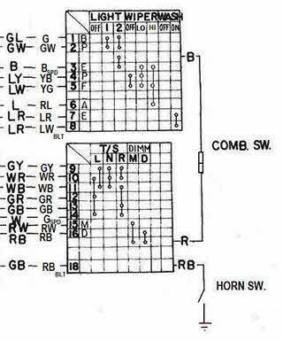 2 points
 -
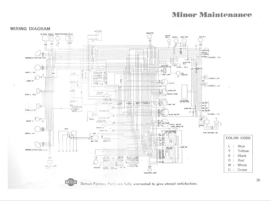
2 pointsSeveral years ago, I worked with your #2 schematic ("Datsun Factory Parts are fully warranted to give utmost satisfaction") and then added editing comments, using the wiring, connections, and devices in my car (unmolested 4/70 240Z) as my primary guide. See attachment #1. Back in 2015, CZCC member @EuroDat (Chas) did a beautiful job of creating a full-colour wiring schematic based on the specs for MY-1970 USA-Cda cars (see attachment #2). It addresses most of the issues that I identified in my own review. S30 Wiring Schematic - 70 240Z - B&W - 70 Owners Manual - Comments added for errors 7.pdf S30 Wiring Schematic - 70 240Z - Colour - Eurodat.pdf2 points
-
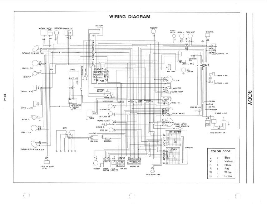
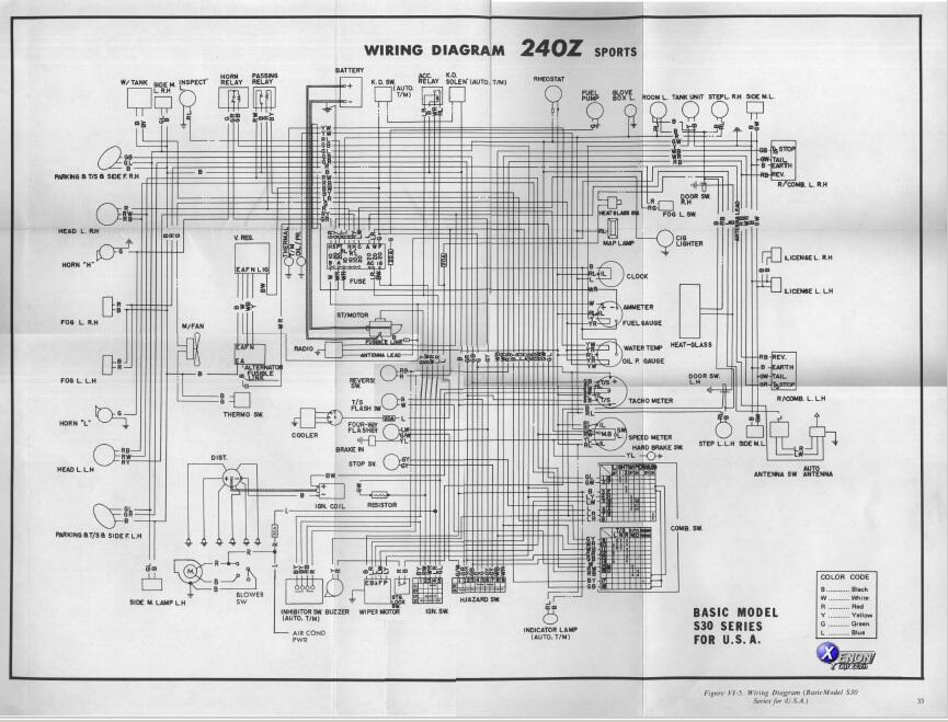
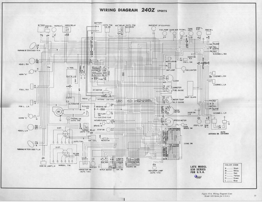
1 pointI've poked around looking for a wiring diagram for the early cars (1970) and haven't come up with anything really good. I've turned up five diagrams so far, and they all are questionable in accuracy. This is clipped from a 1970 owners manual: This is another version, supposedly from the owners manual: This is clipped from a 1970 Factory Service Manual - Body Electrical section: And here are two versions clipped from the Service Manual Supplement, which I believe came out for the 1971 model year:
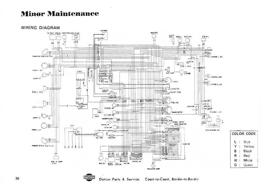
 1 point
 -
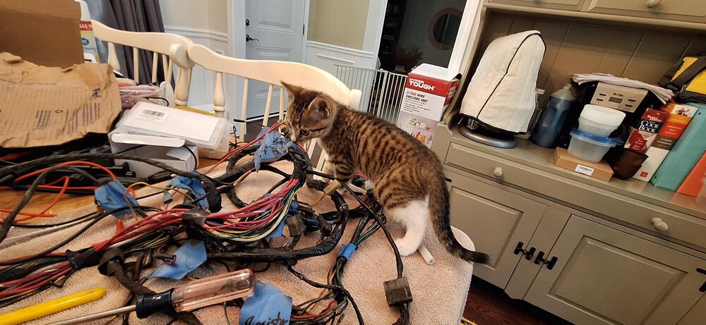
1 pointThe wiring work is getting inspected, and I've barely even started.
 1 point
 -
1 pointI will post how it comes out and $ info. He is away until next week. i am sending him some photos for pricing options.1 point
-
New gears and used gears will have different wipe patterns. That said, my 4.11 gear set is used. I should have taken a wipe pattern before I took it apart. Had I done so, that would be the reference I could be using now. I am going to assume that my 4.11 gear set should have a wipe pattern more like that of the stock diff I posted pics of yesterday, and attempt to start again with the .126" stock shim in place, but start altering the ring gear position to reduce the backlash. I'll see where that takes me on this trip of experimentation with wipe patterns.1 point
-
1 pointThanks! It depends on whether or not I make the dashboard wiring harness a blocker. If I don’t then I only need to jump some wires in the engine harness, make battery cables, fill the radiator, and bypass the heater. I have everything necessary to do those things, so I could theoretically finish all of that in a week. I also need to decide if I am going to fill the gas tank now or have the supply come from an external tank. Oh, and I need to get the transmission into neutral without having a shift stick, clutch cylinder, or clutch pedal in the car.1 point
-
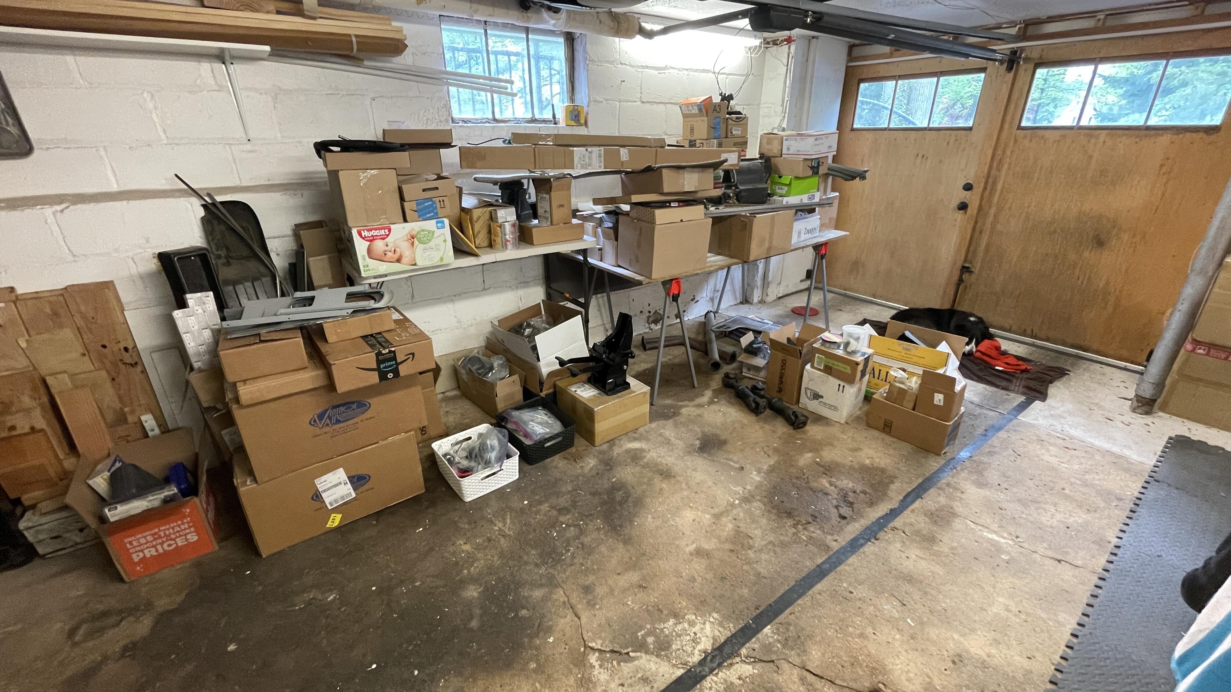
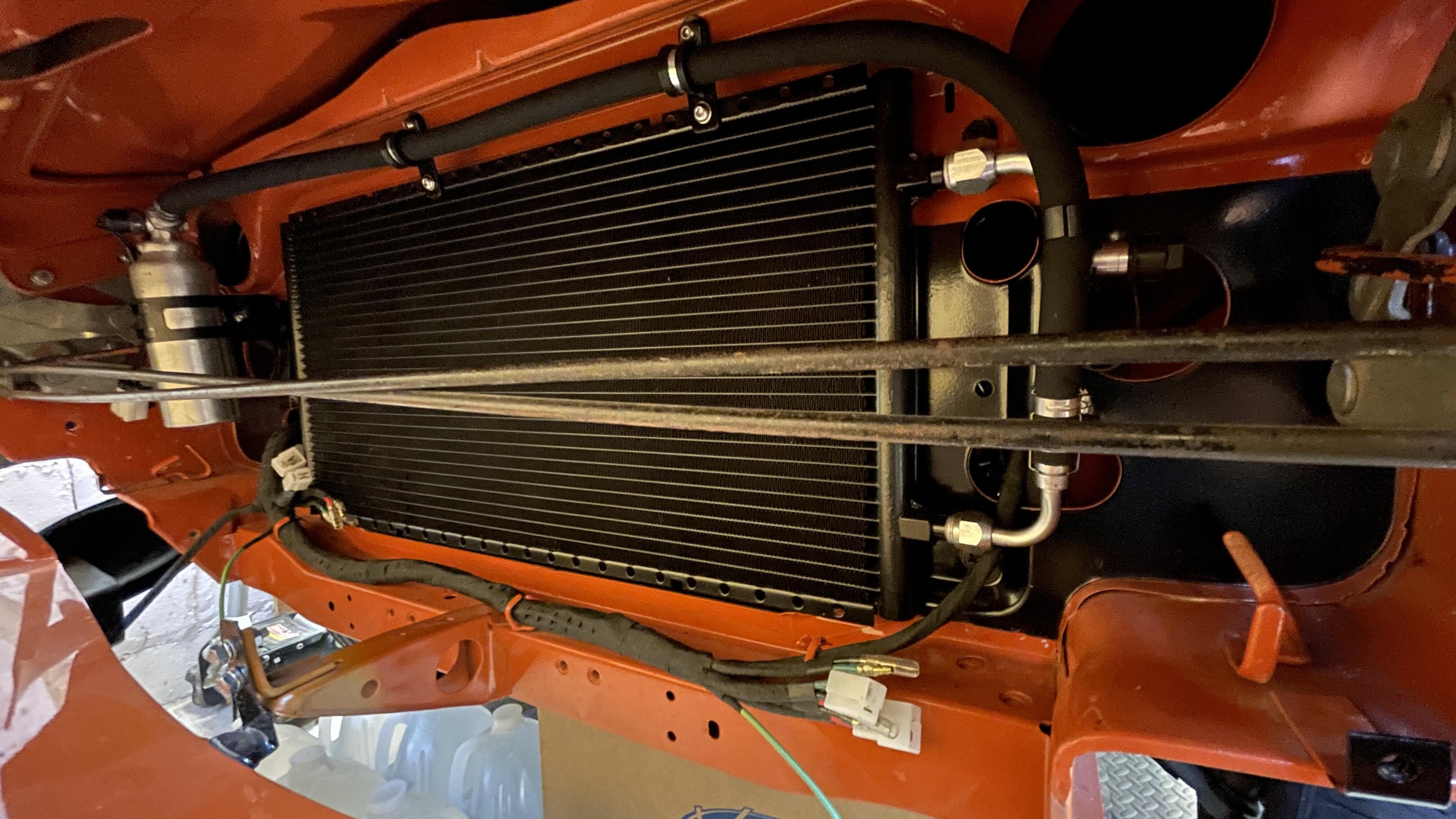
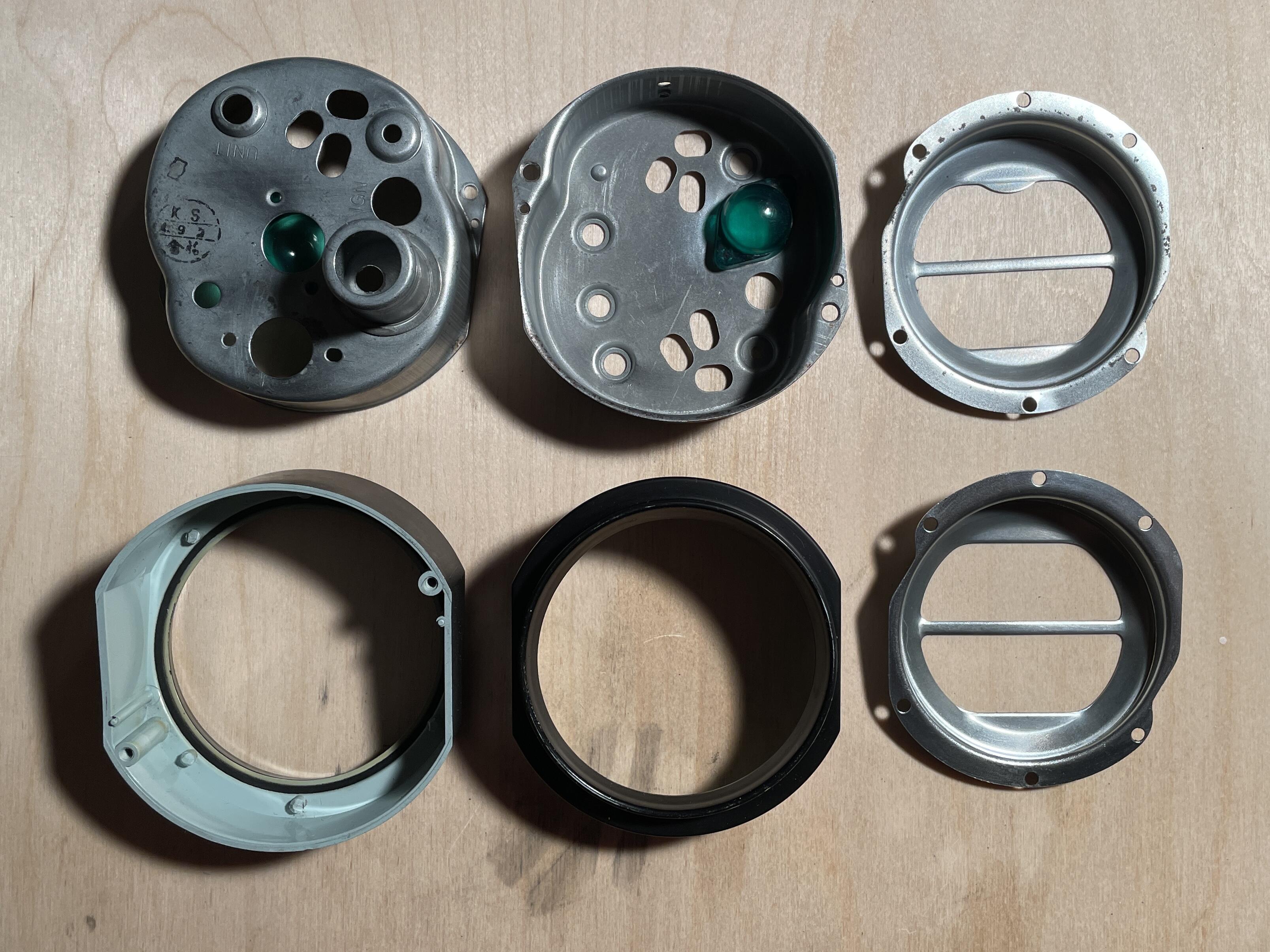
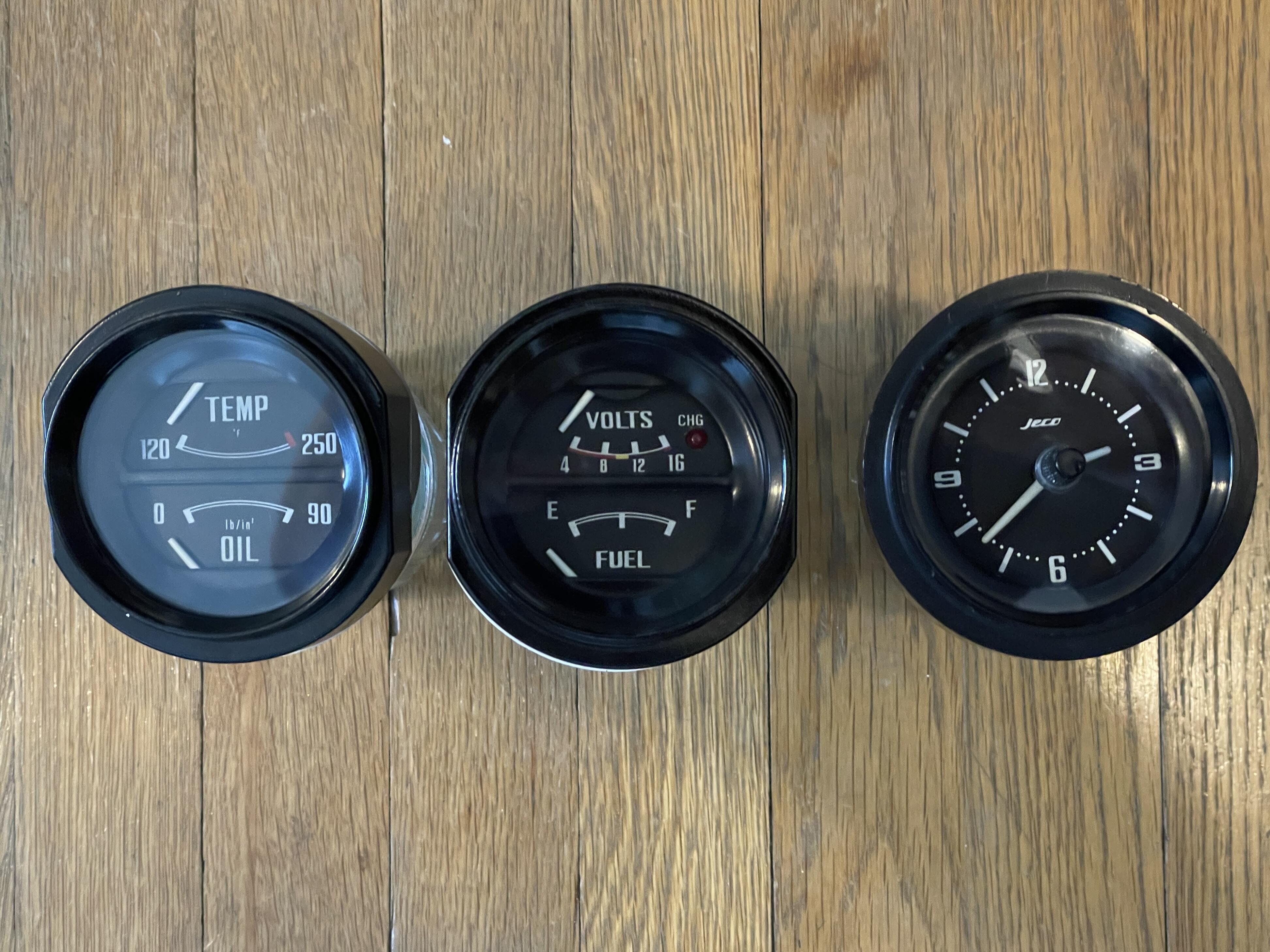
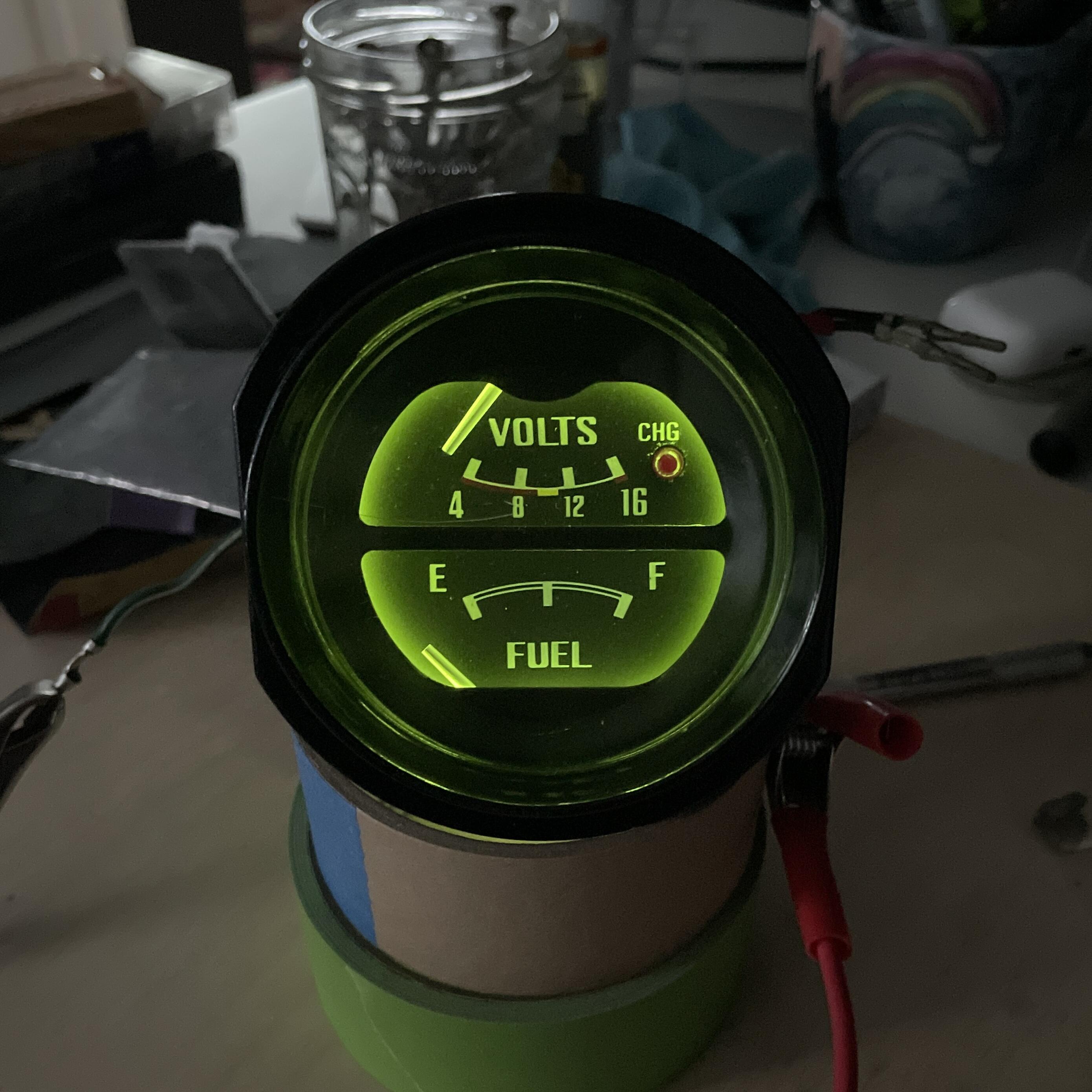
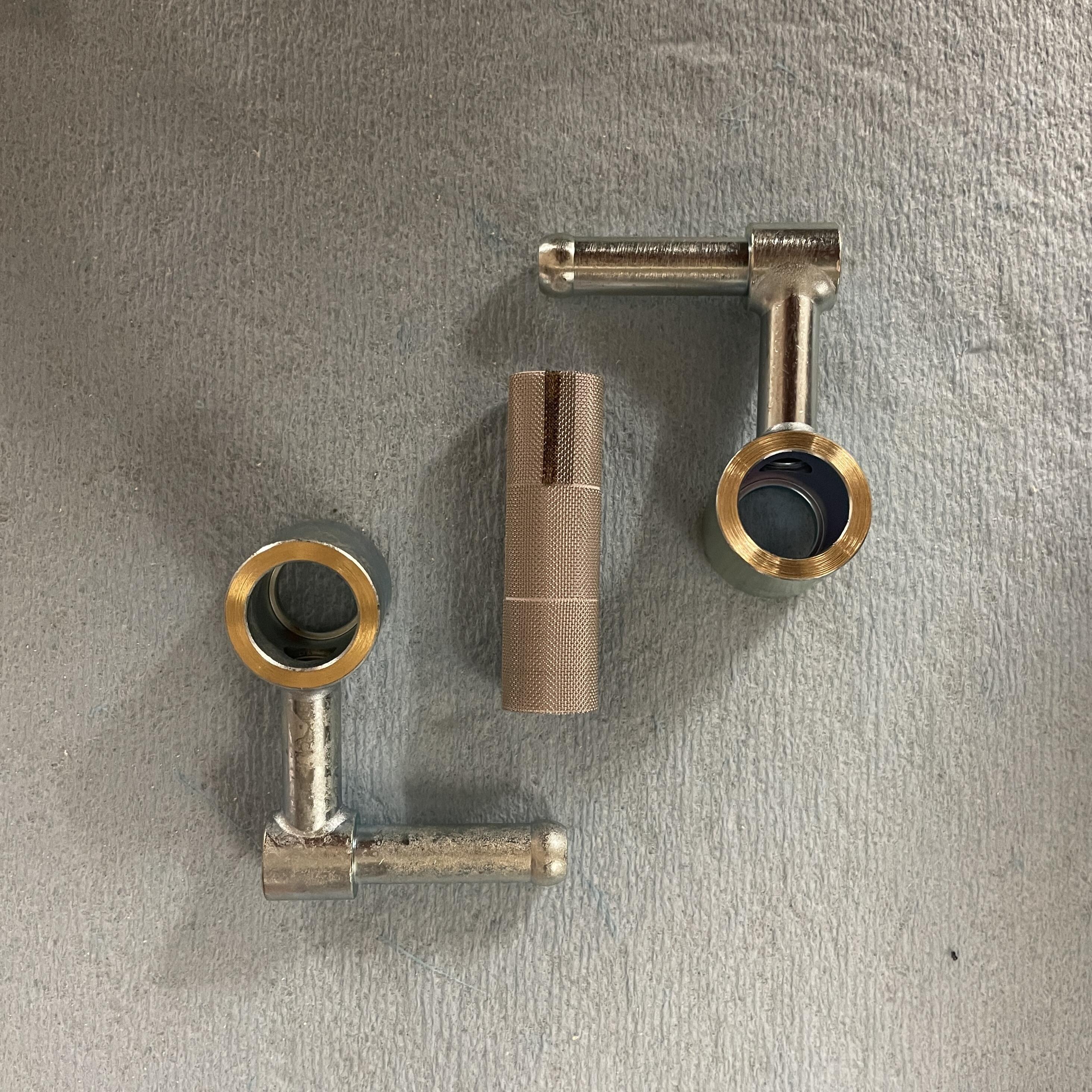
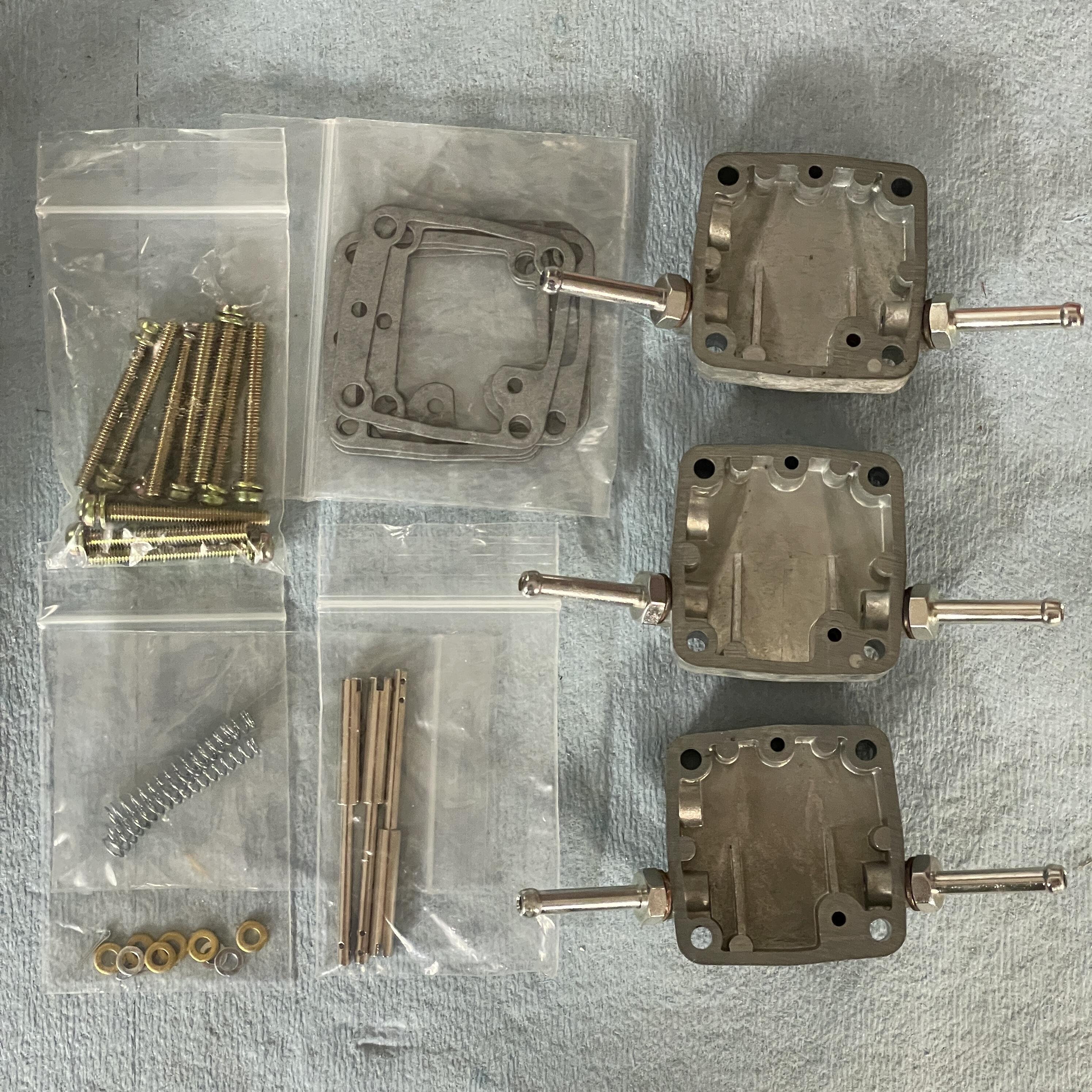
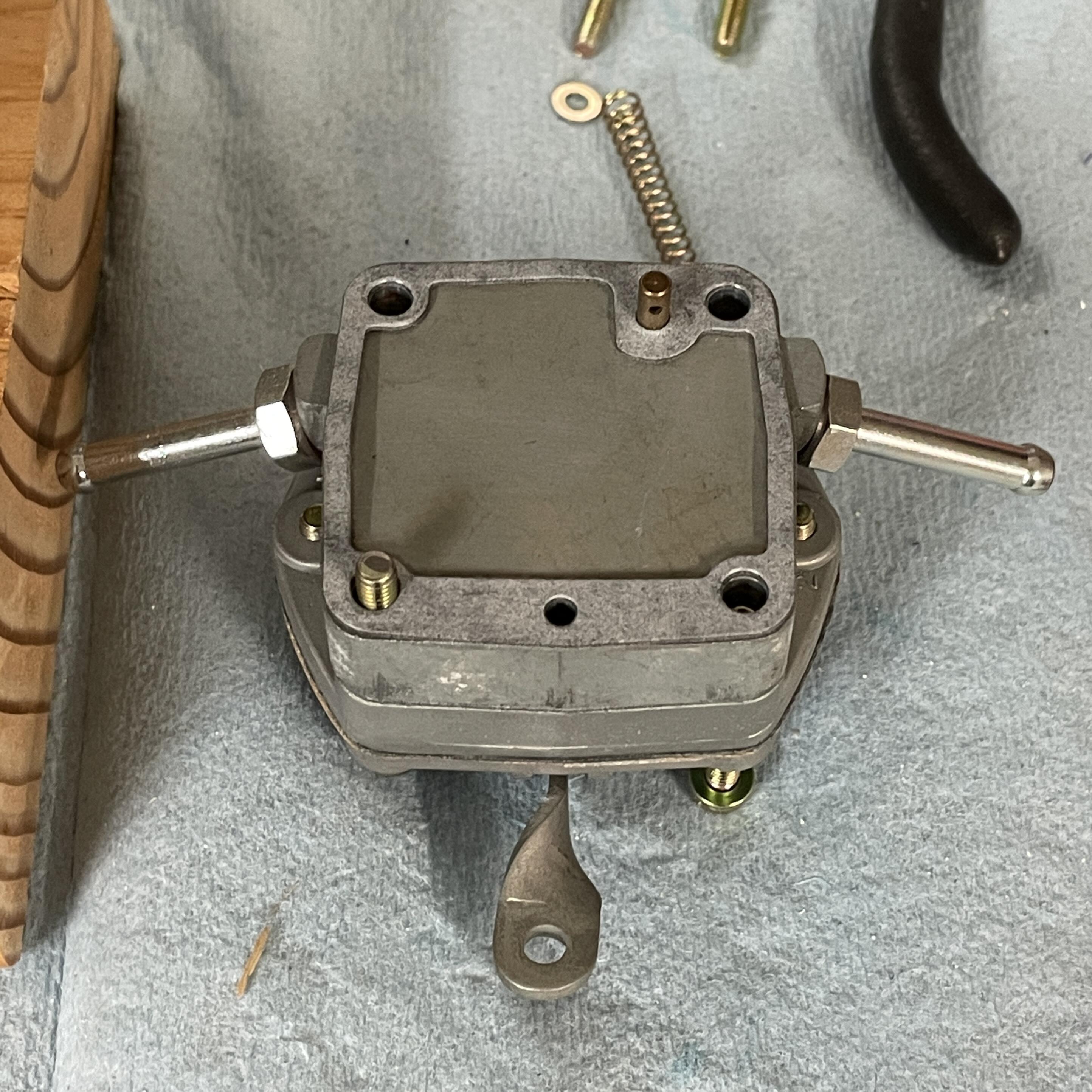
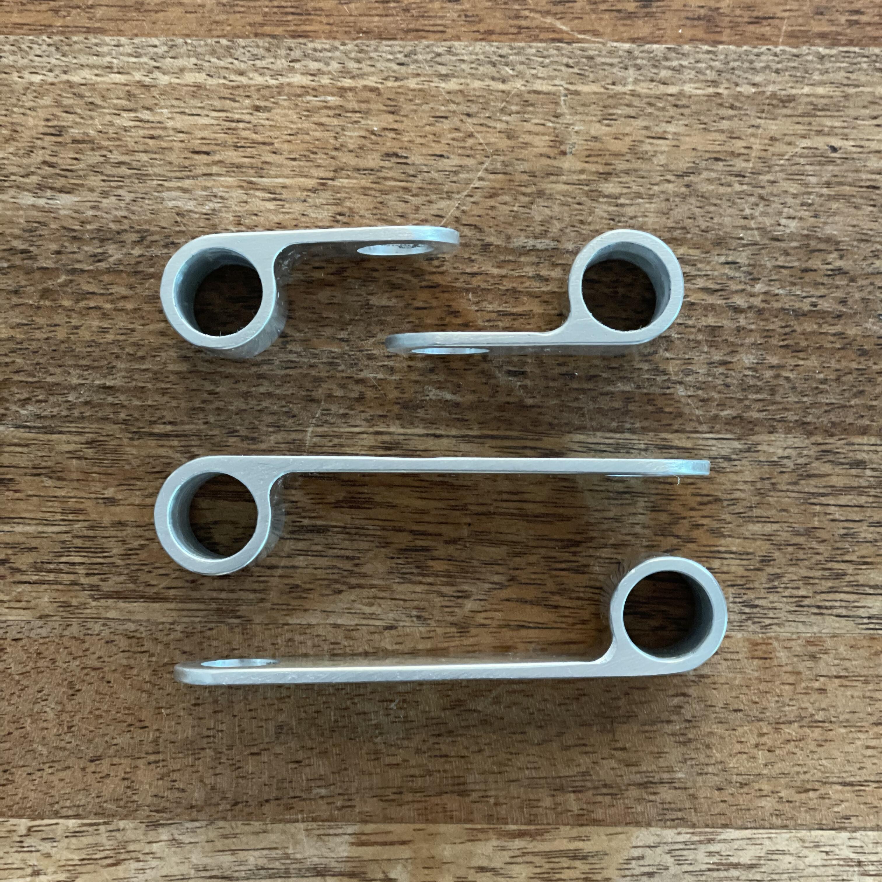
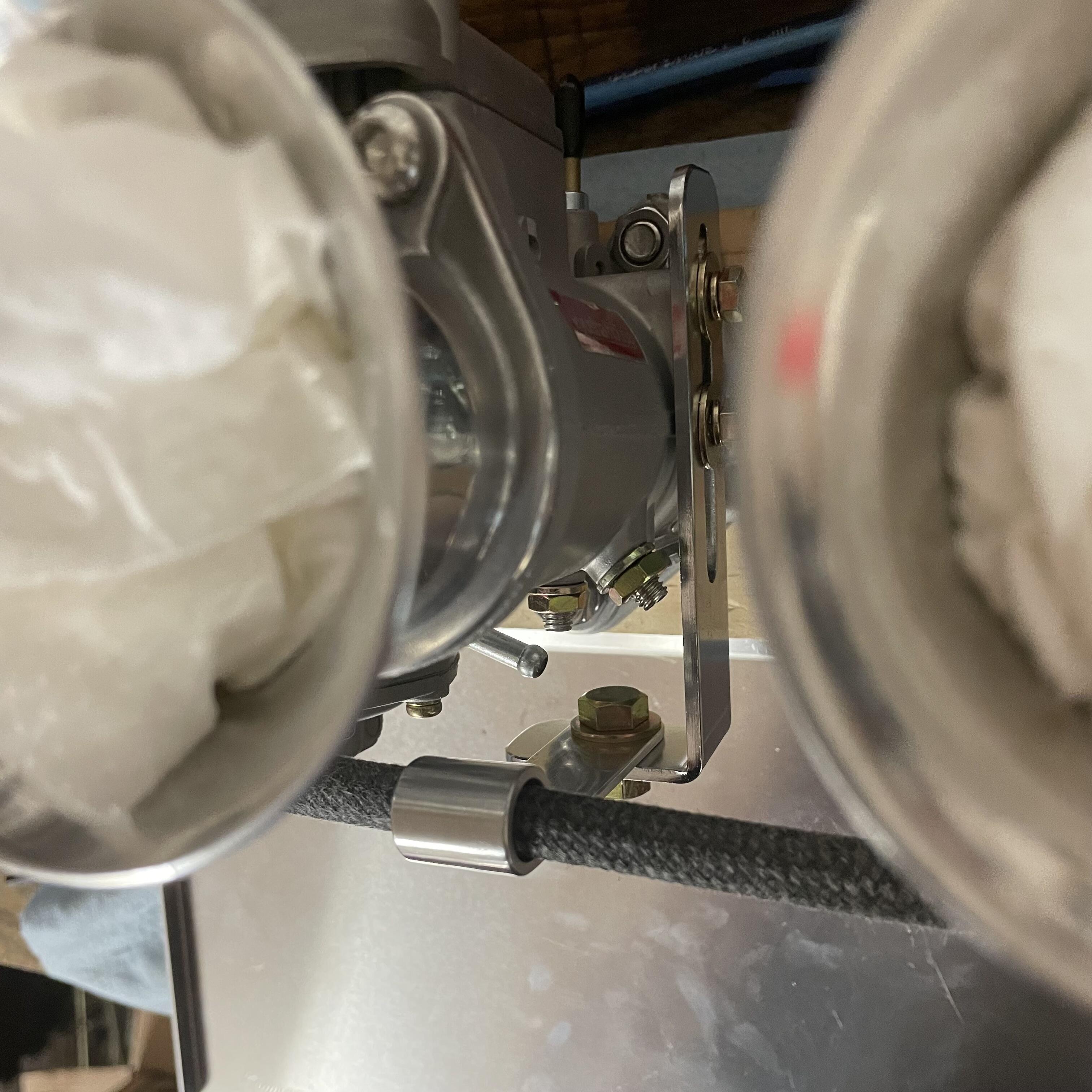
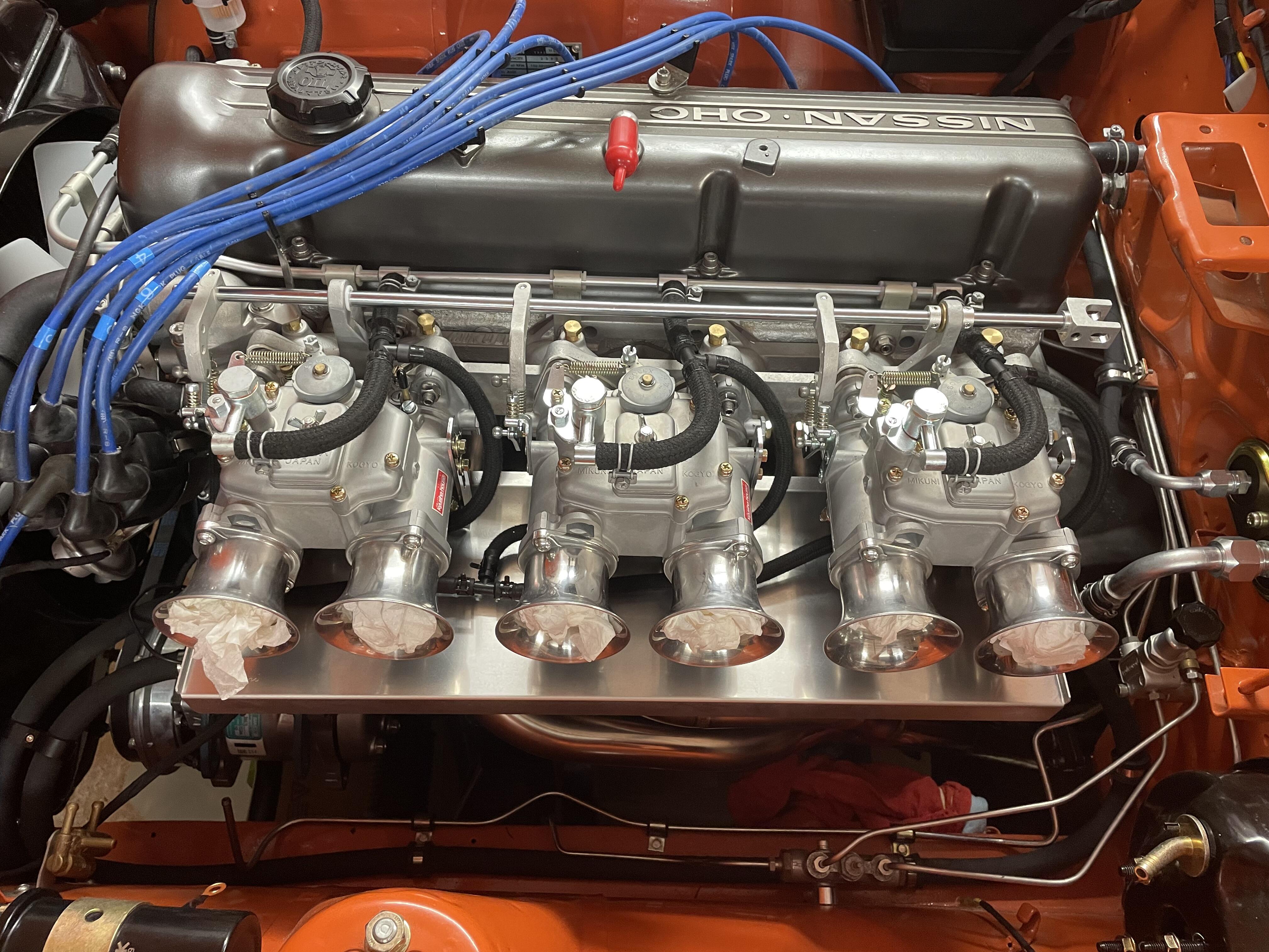
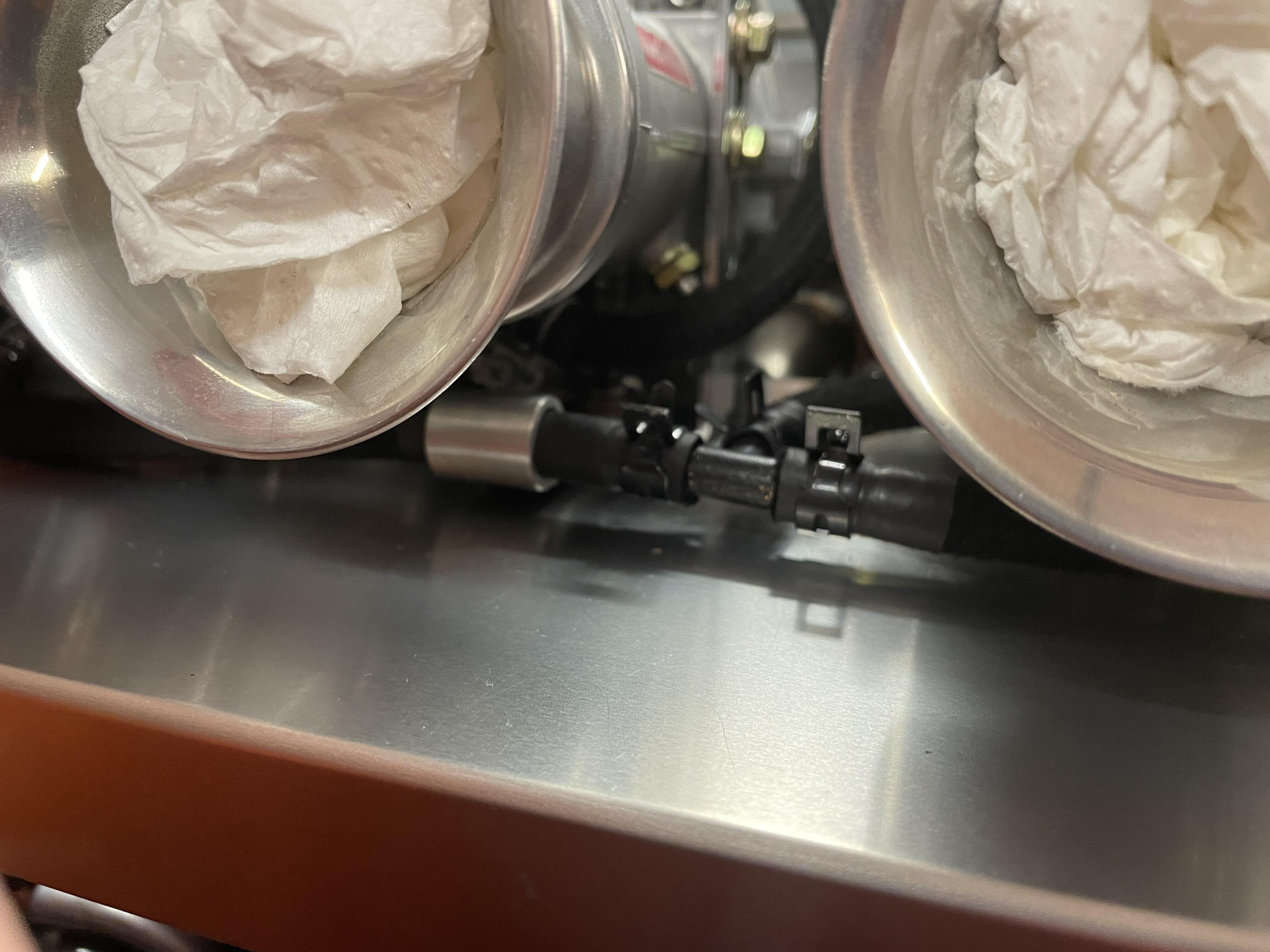
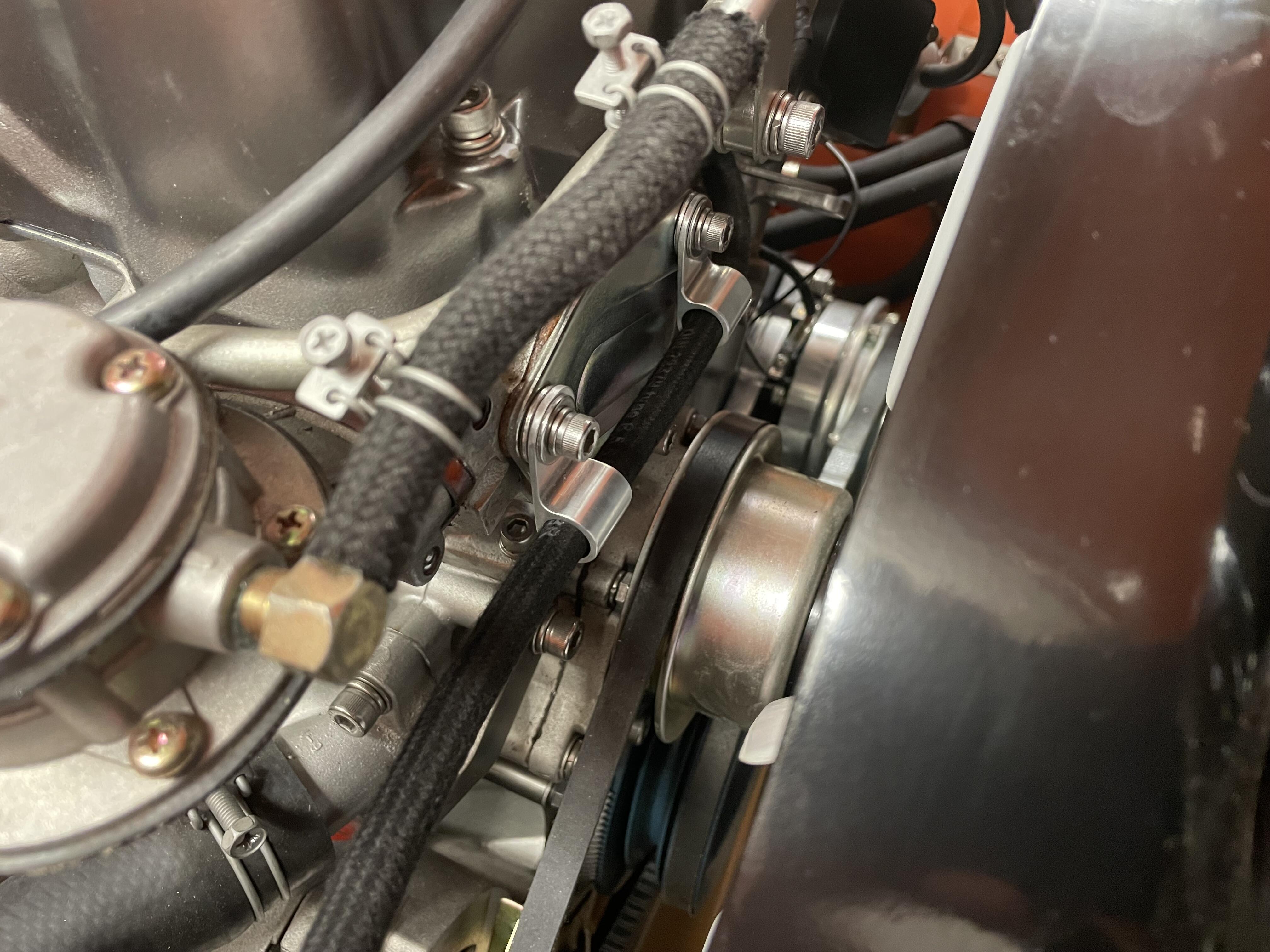
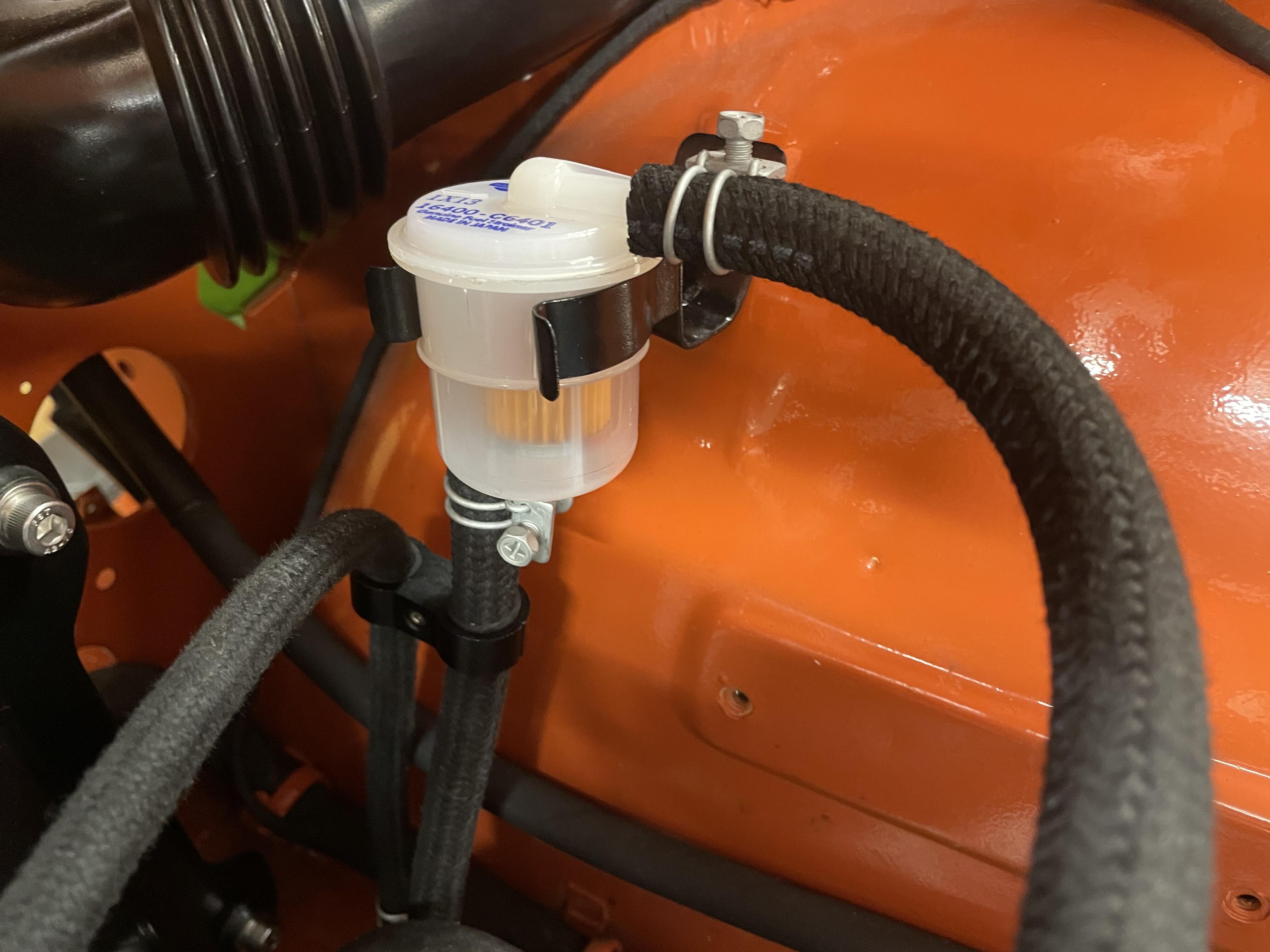
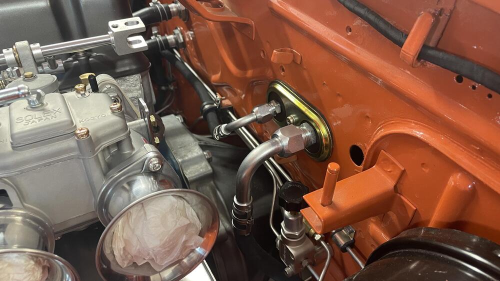
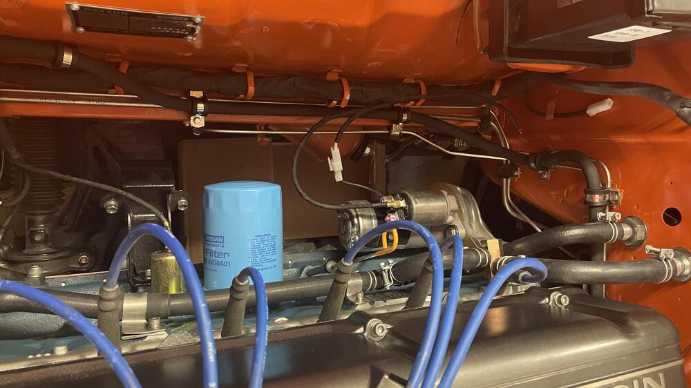
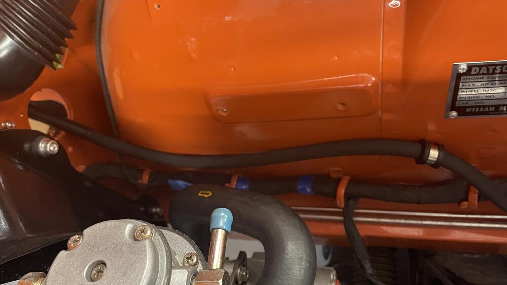
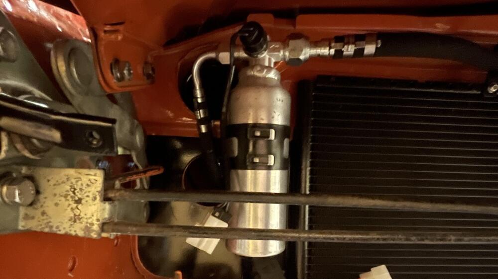
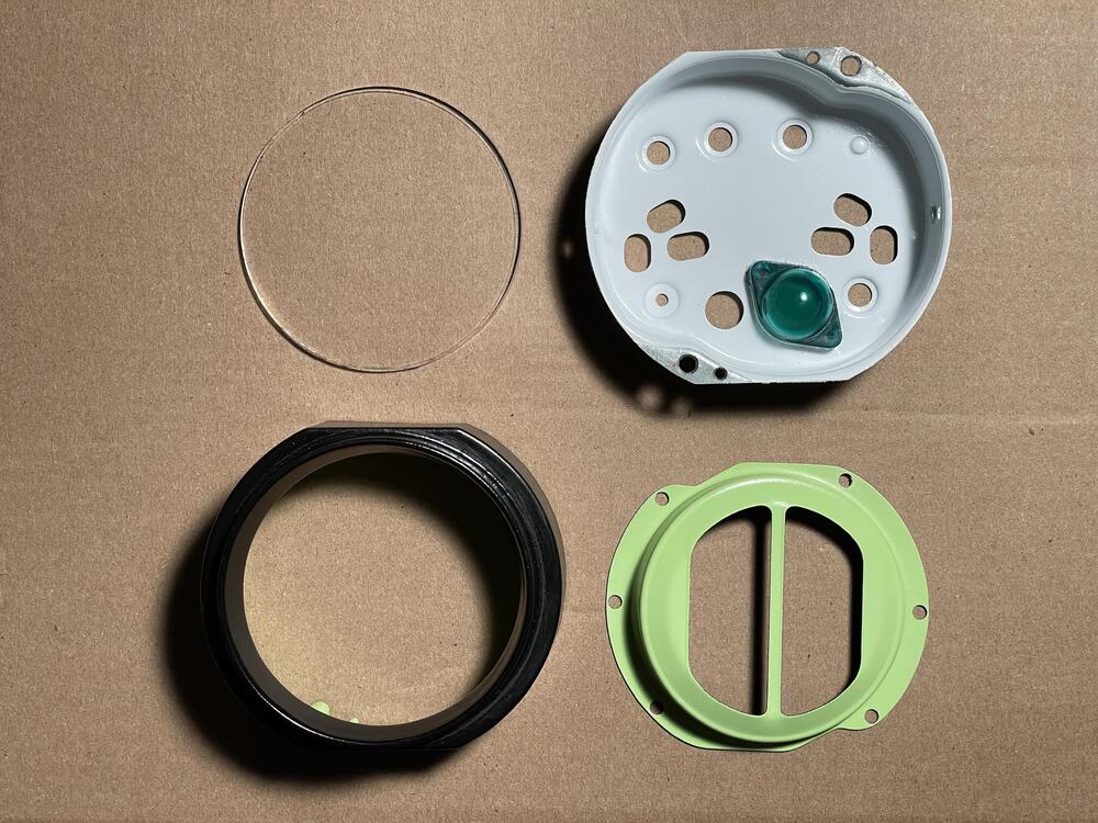
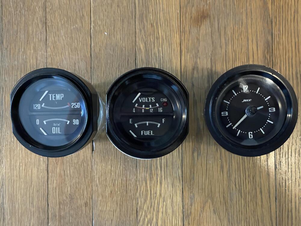
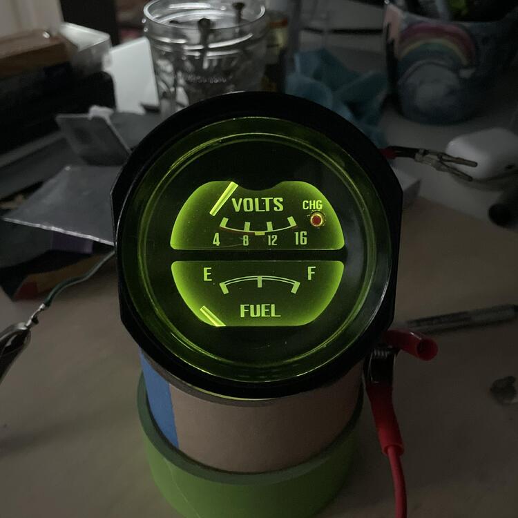
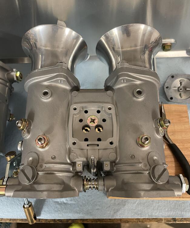
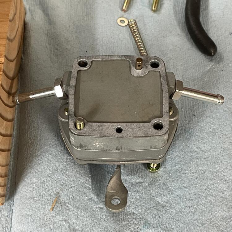
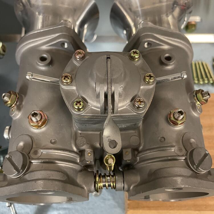
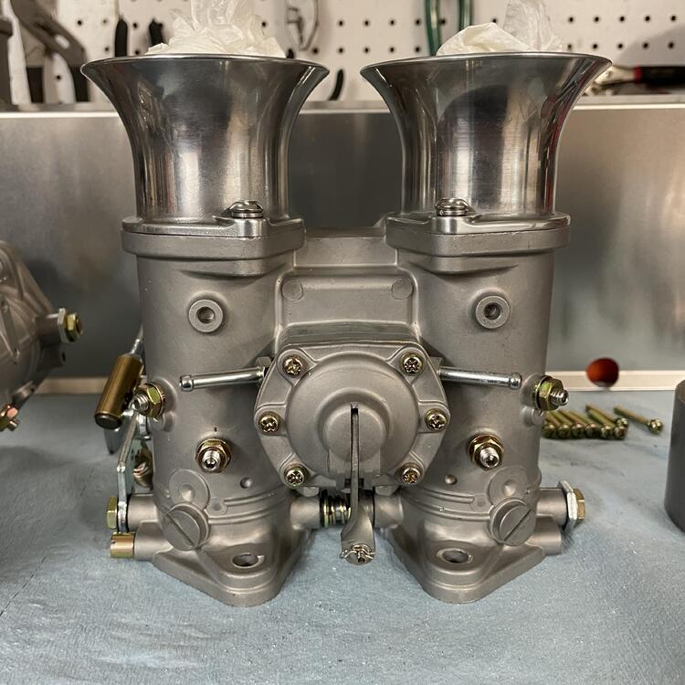
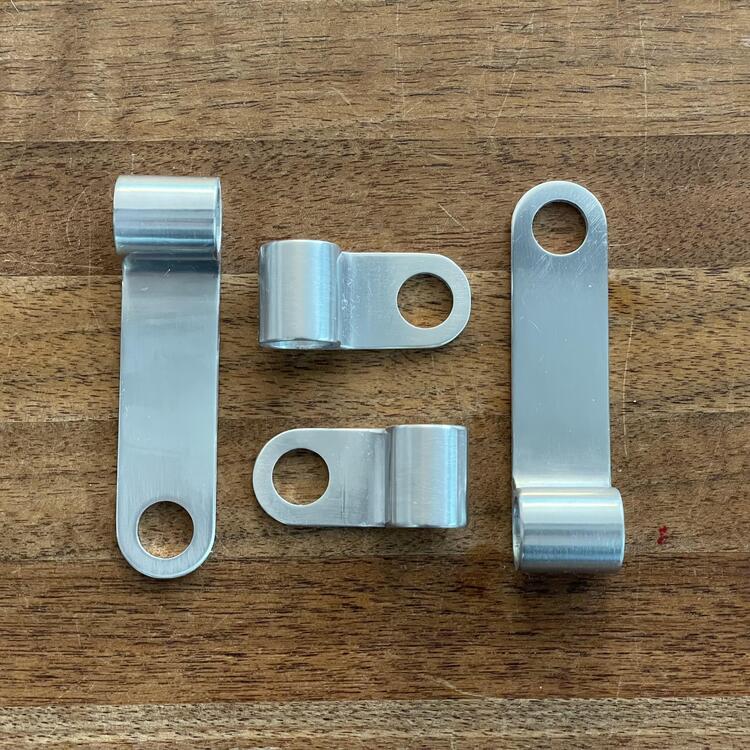
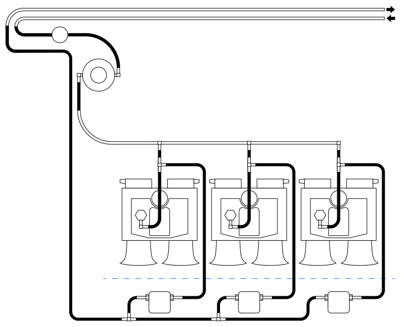
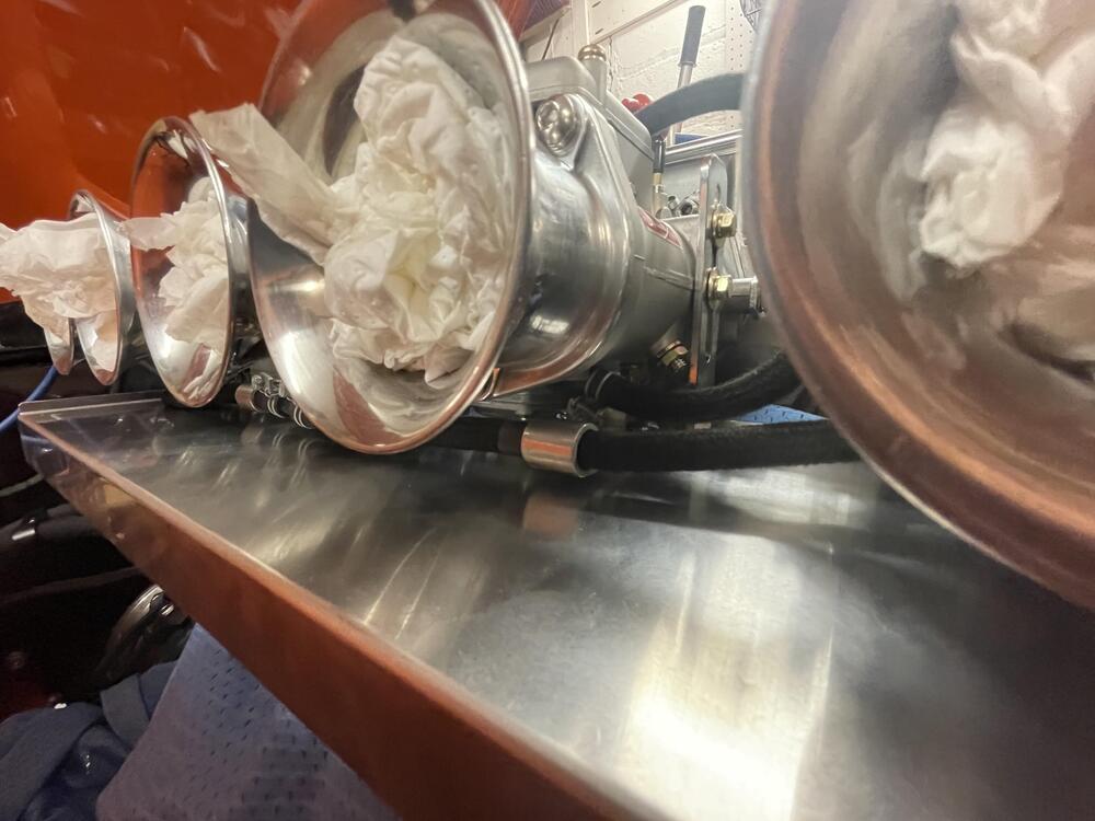
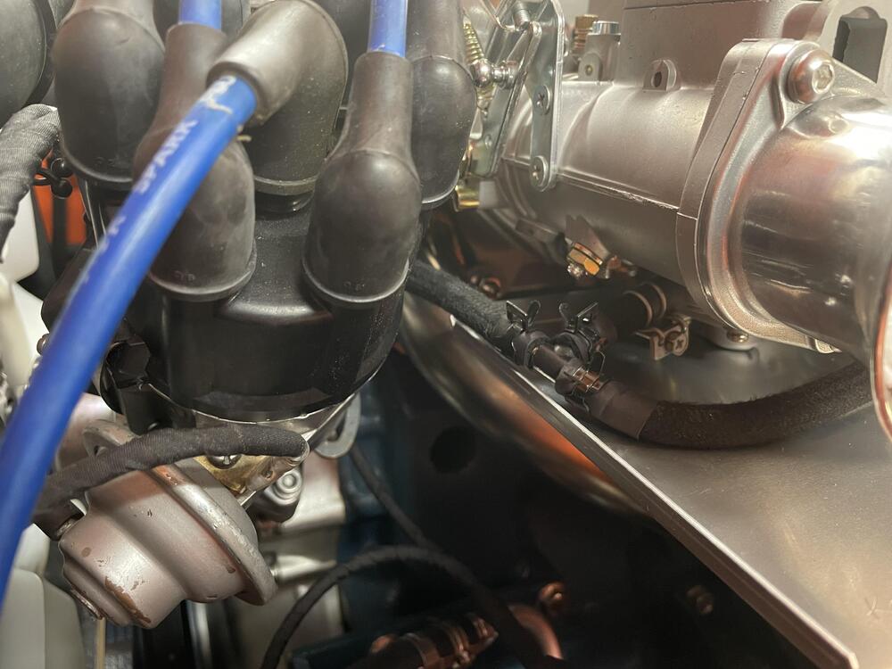
1 pointSome progress: Reboxed all my parts. It really drove home how much work I still have in front of me. ••• Wrapped up the remaining AC lines. Pretty pleased with how these turned out. Hopefully they don’t have any leaks! ••• Refinished and rebuilt my gauges. I matched the green to the inside of my clock rather than the blue from the gauges because the clock was in the best shape. Is it correct? ¯\_(ツ)_/¯ I used warm LEDs, which helped to knock back the intensity of the color. I’m still investigating PWM options to control their brightness. ••• Added some filter screens and cooling bodies to my carburetors. ••• Made some hose retainers for the fuel lines with a friend’s CNC machine. ••• Wrapped up the fuel lines. I may make a rail to clean up some of those cooling body hoses, but it will work for now.


 1 point
 -
Certainly could be.. When I first got my Z, it would suddenly die, sometimes it would restart or not. Thought it was fuel, eventually figured it was the resistor.1 point
-
I used to have trouble trying to figure out what the various diagrams were saying. Then I summed it all up as - "any contact mark pattern that does not overlap an edge is good". Basically, if you can see all of the contact point on the face of the tooth, it's fine. Doesn't have to be in the middle. Just has to be off of any edge.1 point
-
1 pointThanks Jim!! I just contacted him and will be sending out both the DS switch and Hazzard Switch.1 point
-
I bought a Worx pressure washer a few years ago. 1800 p.s.i., 1.5 g.p.m., 115v. It's a good unit.1 point
-
There are rubber seals all over the motor but the hose is 30ft, a long way from the business end of the wand. Actually the motor is rated for nominal 1800 rpm but 1725rpm is the standard speed for single phase, 110 - 120 vac. After using the gas powered PW for years I noticed this unit is much smoother, less vibration and pulsing of the water jet coming out.1 point