Leaderboard
.JPG.cfcada9cf1c1b502df3f5f2f2ca3ff36.JPG)


Popular Content
Showing content with the highest reputation on 10/30/2023 in all areas
-
I was just following @Zed Head's reasoning to a possible logical conclusion.3 points
-
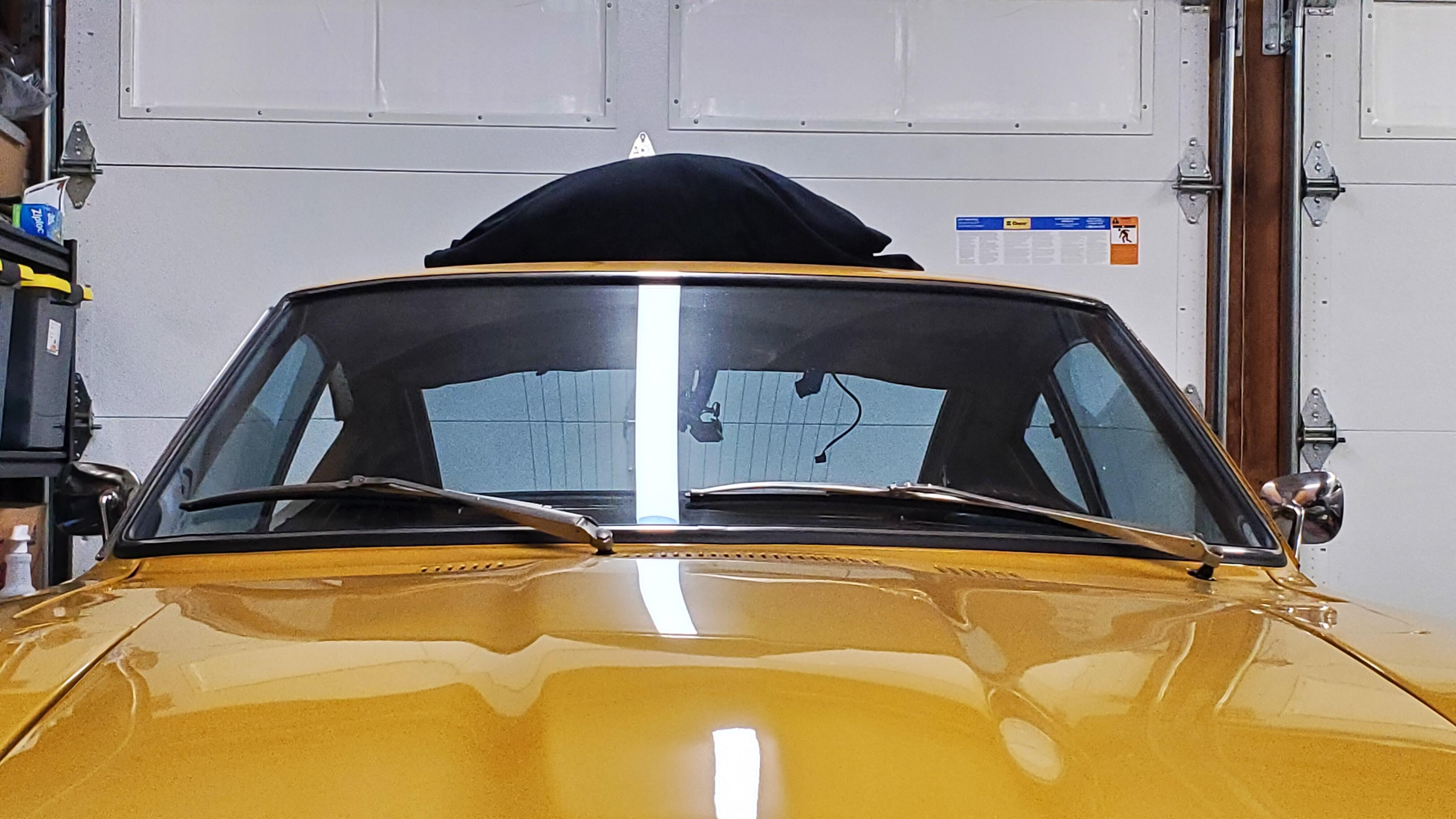
3 pointsOK so i mounted the mirror today and am very pleased with the results. Symmetry is perfect, not a great pic because of limited space but best I could do: Now for sight lines, not "perfect" but certainly usable. I don't have seats in yet so I had a couple of cushions in there and I tried to simulate where I would be. To fully see a normal viewing angle you do have to lean in towards the console a bit but not like you're falling out of your seat. A stretch of the neck basically gets you there. I'm only 5'9" so I tend to sit a little forward and what if seems like is if you are a taller fellow you'll be in a much better position the further your seat is back away from the steering wheel. It will be a long time till i get true seats in so I'll remember to check back in with some shots from the normal seating position and report back in. Overall I give it a 9 out of 10. @Patcon yes i think if you swapped out the glass it goes from a 9 to a true 10. It looks to me like you can get the glass out by uncrimping the metal shell around it and then i assume the glass is glued to the back plate? I won't be trying that any time soon becasue my luck the glass cracks, the ball breaks and I'm back to square 1.
 3 points
 -
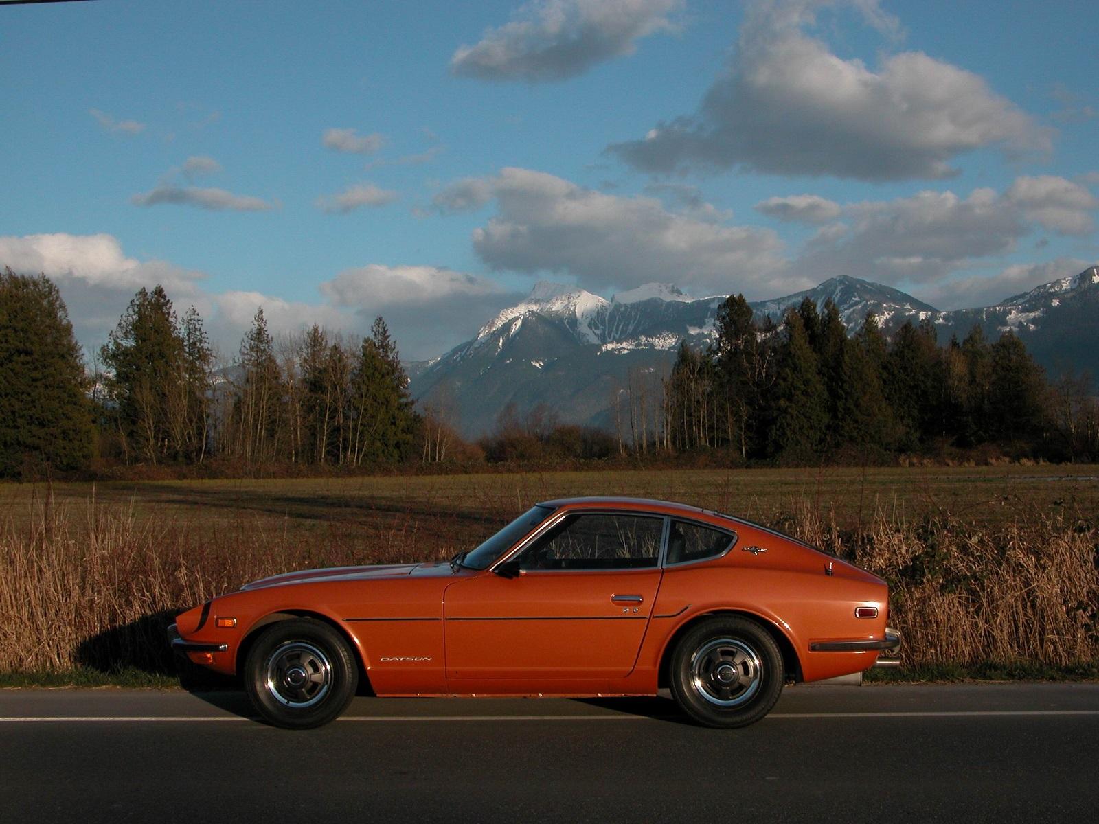
2 pointsHS30-H model Fairlady 240ZG went on the market in Japan around October 1971, so that would correspond.2 points
-
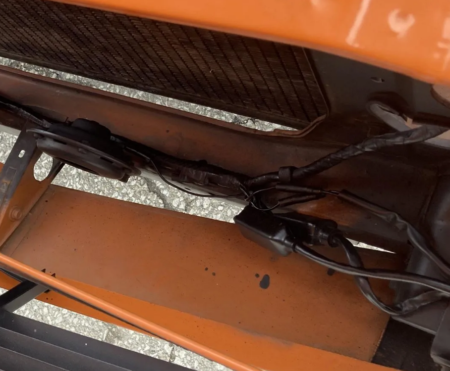
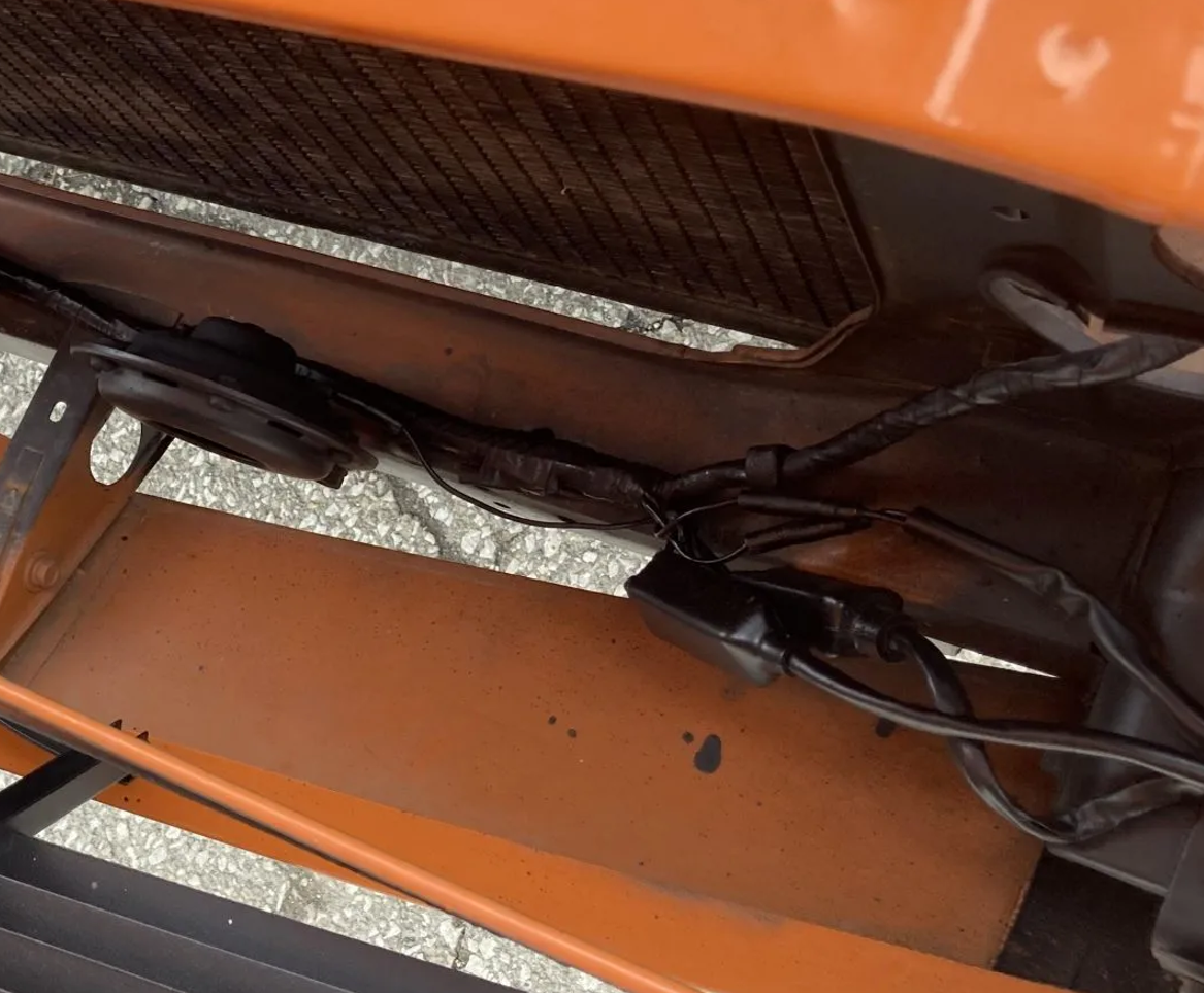
2 pointsGreat info, thanks for clearing it up. After looking at images on BaT it looks to me that the extra reinforcement with the M8 x 1.25 threaded holes was added to all chassis production for the '72 model year. Here is an image of from HLS30-43540 (9/71) without the the holes followed by an image from HLS30-52950 (10/71) that has them.
 2 points
 -
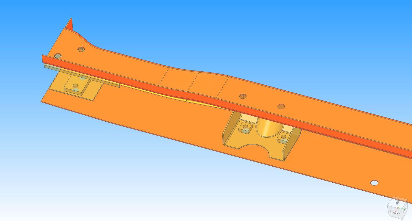
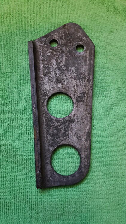
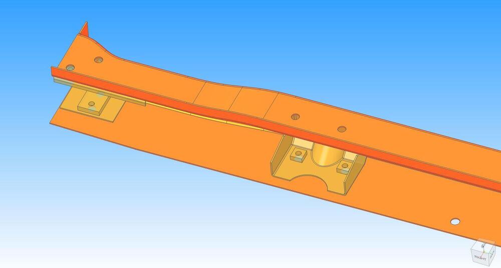
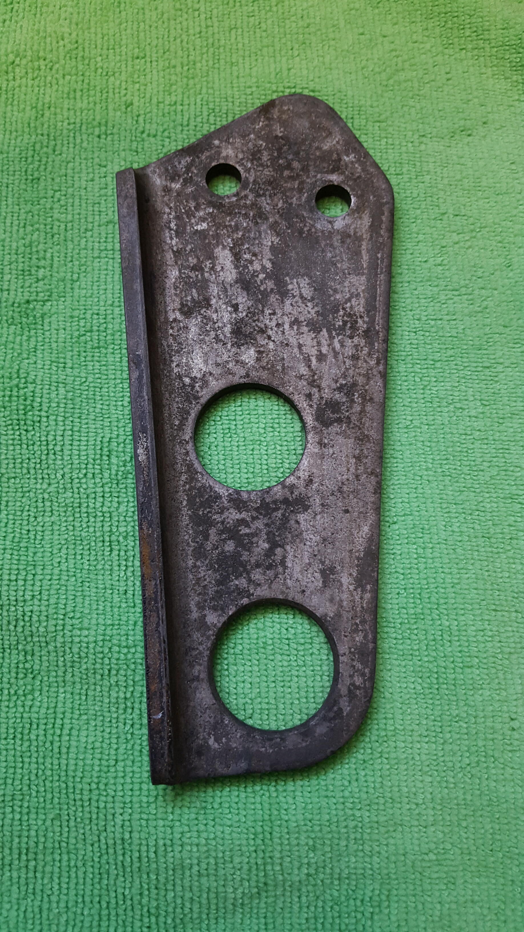
2 pointsThat's the attachment point for the towing bracket specific to the HS30-H model Fairlady 240ZG. The stock short nose towing bracket could not be used on the 240ZG (the lower section of the Grande Nose covered it) so the factory created a 240ZG-specific towing bracket which allowed the tow rope to pass through the nose:
 2 points
 -
2 pointsFiche suggests there was a change on July 1972 https://www.carpartsmanual.com/datsun/Z-1969-1978/body-240z/roof-panel-moulding-sunvisor-head-lining Somewhere later than that they grew pockets too. Mirrors too??? Naw.2 points
-
I've wondered if it's a misunderstanding in raising and lowering the nozzles by way of the direction the mixture nuts being turned.
 2 points
 -
2 pointsI should clarify. I haven't driven more than 1 hour in the dark in any given drive. I have driven in the dark plenty of times with these bulbs without issues.2 points
-
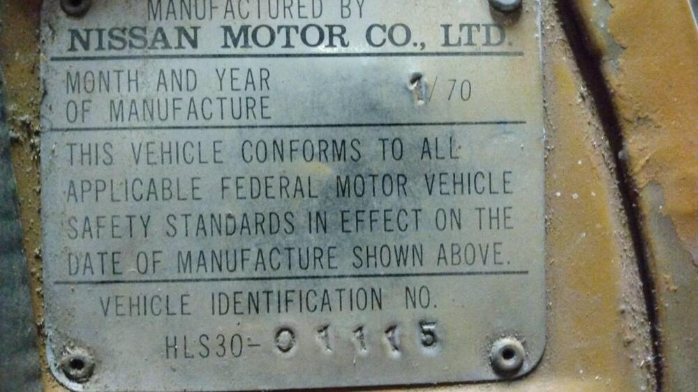
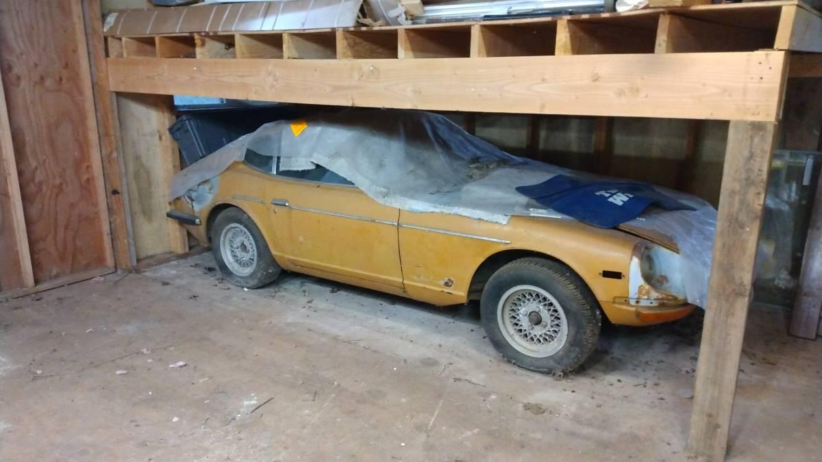
Another early 1970 Vin 01115 up for sale near Portland OR. $8K https://corvallis.craigslist.org/cto/d/albany-1970-datsun-240z-series-jan-70/7682266894.html There are more pic's and Info in the ad.


 1 point
 -
Mystery solved @Zed Head @SteveJ thank you both. You got it, Steve. Pulled the valve cover again and took a look. The rocker had jumped off the lash pad to rest on top of it. Not sure how I missed this obvious problem. Anyways, popped it back in place, cleaned the spark plugs, and it now runs like a top. It is cammed and I checked the valve lash and it actually looked perfect for the stage one Comp Cam. Not sure how it popped off then? Must have happened on start-up yesterday, somehow. Any ideas on why this may occur? I will see if that ticking noise is gone for good once it's cold. I haven't heard it since during this process. It is possible that maybe the rocker had been working its way off for a while, and reached its final straw. Still no conclusions for the oil on plug. Could be that the rocker wash pushing valve at an angle. No smoke out tailpipe again. People be wary of going straight to EFI for diagnosis, the loss of compression was throwing off the vacuum and AFM vane enough to cause woes in that system.
.thumb.jpg.ad8463e6052d60128de8fa5bfba01bb4.jpg) 1 point
1 point -
I found this on someone's car about a year ago. Cylinder 2 was reporting zero compression. The valve was mis-adjusted and the lash pad eventually turned on its side.1 point
-
Turn the engine over by hand and see what the valves do. If a valve stays down you should be able to pop the rocker arm off. Might be able to grab the stem and spring retainer and pull it up. Maybe it's something simple like a broken or weak valve spring. Or a rolled over valve seal. It's odd that you would have oil in the cylinder after sitting overnight unless a valve seal wasn't doing its job. Get #1 up on the compression stroke and that should give the most space between cam lobe and rocker arm. Hoping for damaged valve seal and no bent valve...1 point
-
@Zed Head good point, 1 was very wet with fluid all over (smelt like poorly burnt gas) and 4 had little dots of moist stuff on them, but weren't soaked. I think I will do a compression test this week to see if a head gasket is possible. No mixing of oil or coolant, so only failure would be from cylinder to atmosphere or between cylinders. Oops my fault, forgot to mention I am running the Pallnet fuel rail with an aftermarket FPR. I can check to see if anything is leaking through the vacuum line.1 point
-
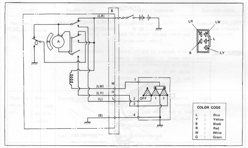
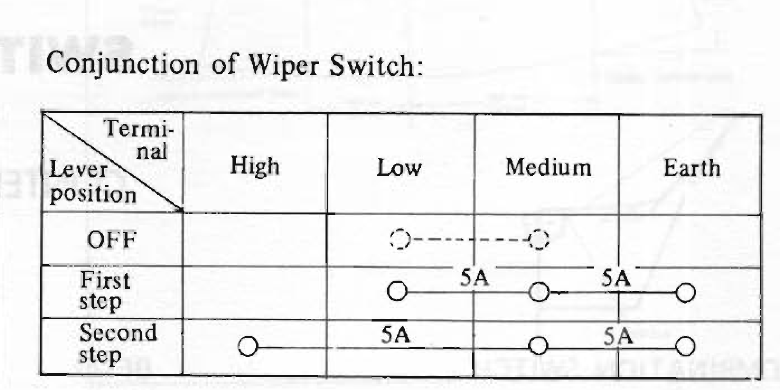
There are two basic sources of confusion with the wiper circuit. How does the circuit work? Where does Nissan explain it? What is the actual wiring? In looking through the BE section and supplements for 71 & 72, it has this rather confusing diagram. In Off, the L & LW wires are connected and ungrounded. When the switch is in 1, the LW and L wires are grounded. The LW wire is the ground for a relay that causes the motor to spin in the proper direction. The L wire is the ground for the low speed. When the switch is in 2, the LW wire is still grounded, and the LY wire is grounded, too. The LY wire is the ground for the high speed in the motor. The 72 BE section also has a truth table that backs up my observations. I am not sure why they show a dotted line connection between the L & LW wires when the switch is in off. From testing, the terminals are connected and ungrounded as I said earlier. Testing the switch operation: Disconnect the negative on the battery. Remove the clamshell from the steering column. Remove the headlight switch. You should see a switch assembly on the bottom of the headlight switch. I looked at several in my collection, and the wire colors were consistent. (see below) Set your meter on resistance. Have the wiper switch in OFF. Test YG to YB. They should have continuity. B should not have continuity with any other wire. (For testing, I put the probes on the solder joints on the switch assembly. Put the wiper in Low. Test B to YG and B to YB. Both measurements should be 0 ohms or close to it. Test B to RL. It should have a large number or OL, depending upon how your meter shows high resistance. Put the wiper in High. Test B to YG and B to RL. Both measurements should be 0 ohms or close to it. Test B to YB. It should have a large number or OL, depending upon how your meter shows high resistance. Report back with your results.
 1 point
 -
How did you create your lettering template? Is it something that could be posted in the resources if you were comfortable sharing?1 point
-
1 point
-
I agree with you. I think one carb is lean and one is rich for some reason. The motor itself I think is good. So lets try to find a way to get the plugs to match. Lets all take a look at the carb and manifold picture if we can get one. Also do you have a carb sync tool?1 point
-
1 pointI have used the Auxito bulbs for a couple for about 3 years now. I don't believe I've driven more than an hour in the dark, either. As for flicker, I haven't noticed it in either of my cars, and I haven't heard of any complaints, either.1 point
-
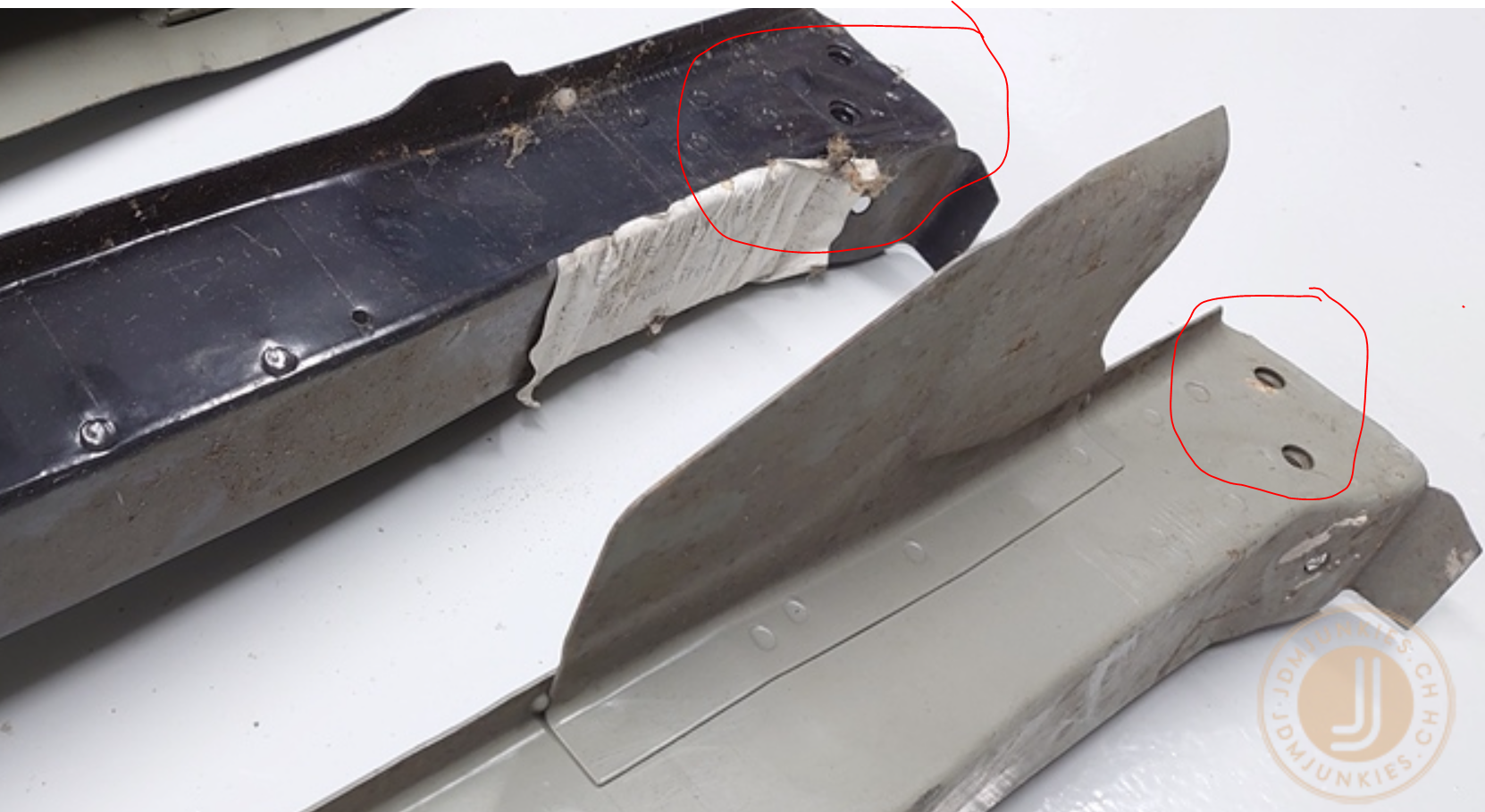
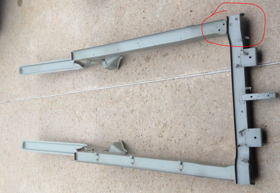
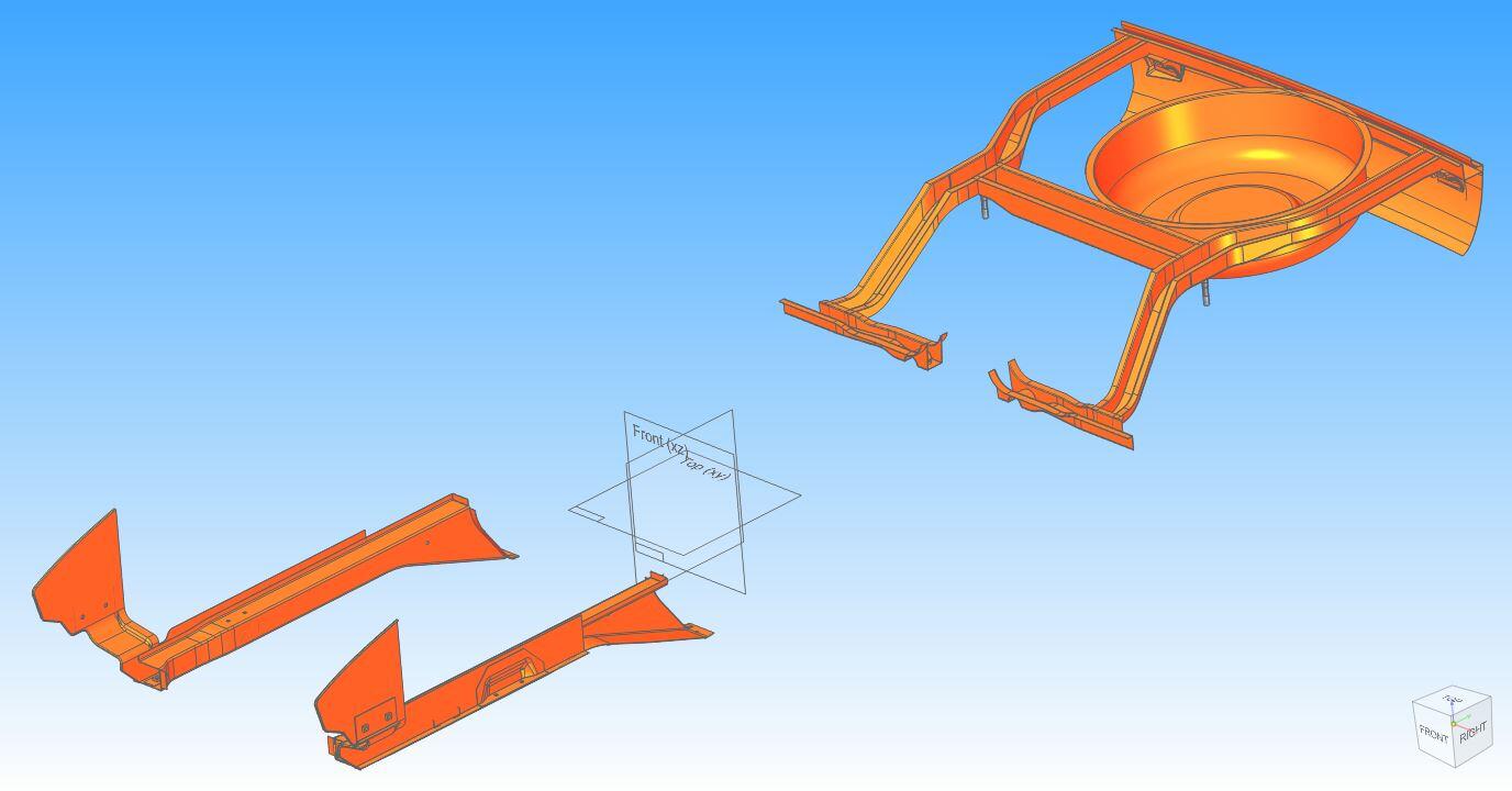
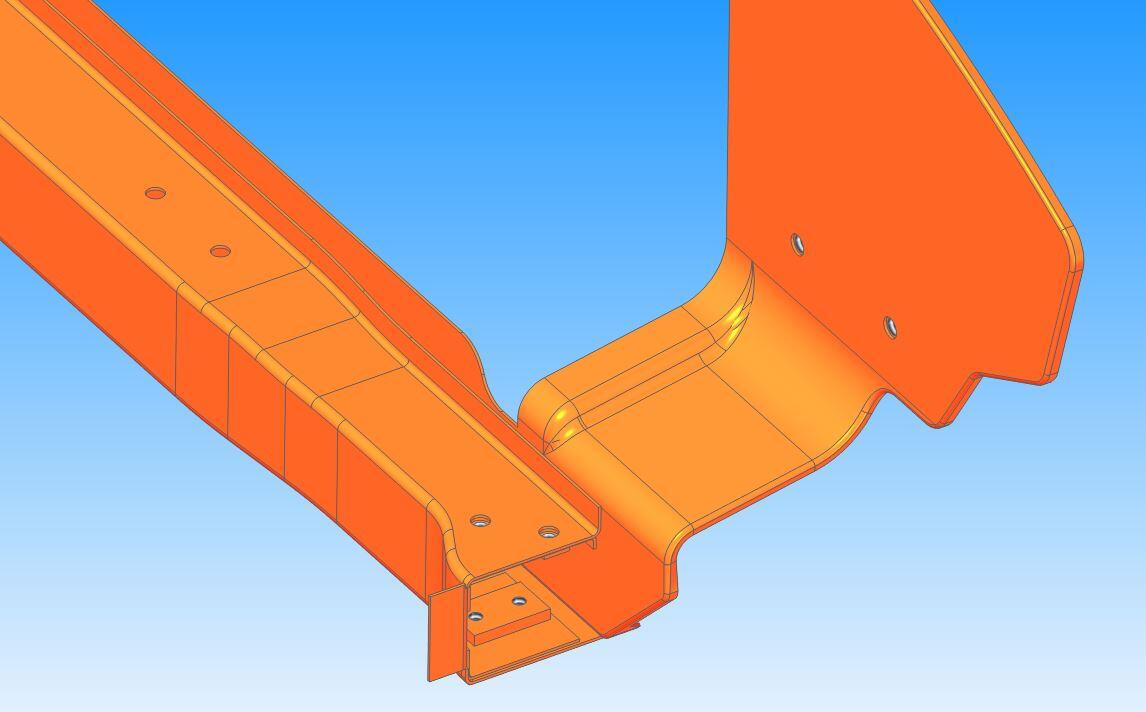
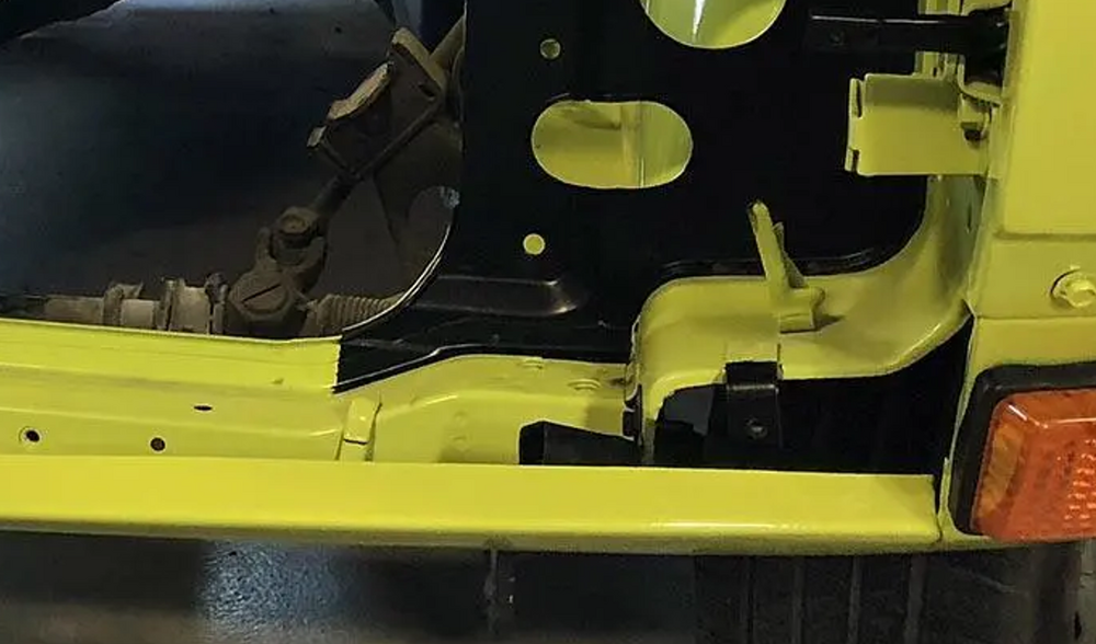
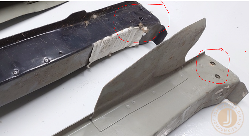
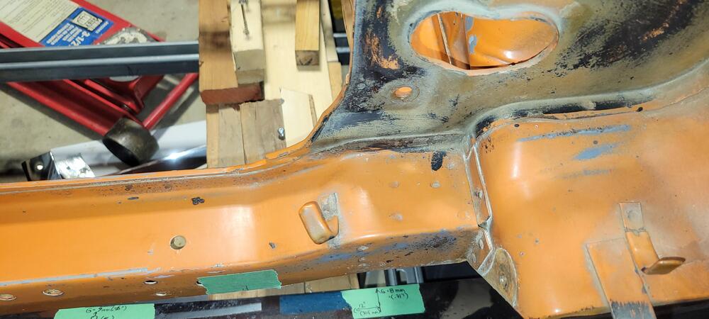
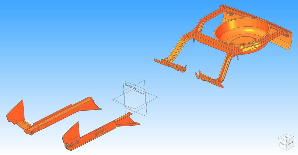
1 pointCan anyone tell me what these two M8x1.25 threaded holes are for? I see them in both the black and gray LH front frame rails above. Here is a pic from an old ebay that has them and corresponding holes in the LH end of the lower rad support x-member. I don't see them on my 7/70 HLS30. These holes are on the replacement LF frame rail I have from KF. In my spare time I have been creating a 3D cad model of my chassis and I have included these holes, I'm just curious about what they for. Here are a few images of my model, it is a work in progress.


 1 point
 -
1 pointExcellent work, and hey those templates look very familiar. Of the full set of tar mat templates I created, those two were the most time consuming. Nice to see they worked out.1 point


.jpg.915ab3838a90021720bcd75cfde2b045.jpg)